Week 4. Electronics Design
Software: AutoDesk Eagle, Paint, Mods.cba.mit.edu Machine: Roland Modela MDX-20. Material: Copper board, electronics
Electronic Design
This week, I redesigned the ATtiny 44 Echo Hello World board and added a button with 10k resistor and an LED with its current-limiting resistor. I had a lot of problem with milling the board using the Roland Modela MDX-20 which I explain in this blog later.
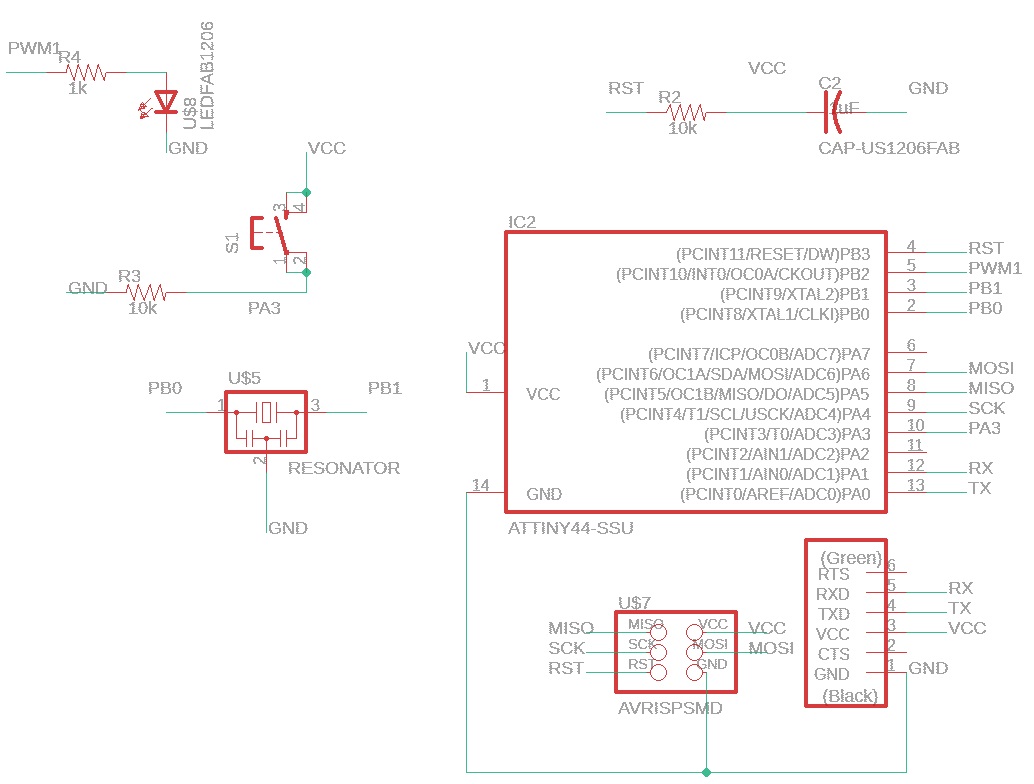
SCHEMATIC DESIGN WITH EAGLE
First, I designed the board using AutoDesk Eagle software which is available free for MIT students. I drew the schematic as seen below. I sed the Attiny 44 Echo World image from Neil as a reference. I added a button with its 10k resistor, and an green LED with a 499 ohms resistor. I didnt do my own calculation, I just trusted that Brian did his calculation for the previous ATtiny45 board since I dont know which datasheet correspond to this SMD LED part. You can definitely do your own calculation using Ohm’s Law and looking at the Forward Voltage and Current of the SMD green LED and the Operation Voltage of ATtiny44. I have a tutorial on how to do this in the Spanish Language Ohm’s Law, Limiting Resistor Calculation. I also have a Spanish Tutorial on how to add a button with a 10k resistor and explained the difference between a pull-up and pull-down resistors.
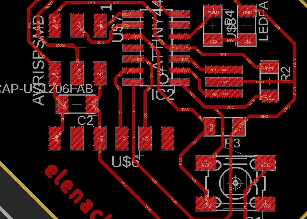
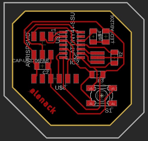
BOARD LAYOUT WITH EAGLE
Then I tried many times to get all the routing done in the board schematic in Eagle. My final layout is shown below:
Use the command line to make laying out easier. Use “route” to create traces between components, “ripup” for deleting traces, “line” for dimension outline, “polygon” if you want to create an entire fillout layer.
EXPORTING BOARD
Once you are done with your board layout. You can do the following commands:
- “ratsnest”, to compile the design.
- “display none top”, this will display just the top layer (copper and traces layer).
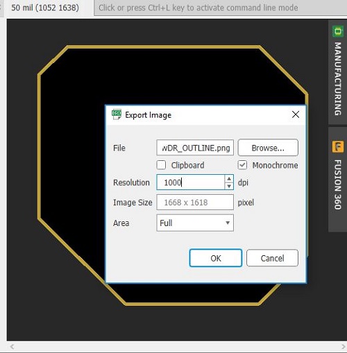
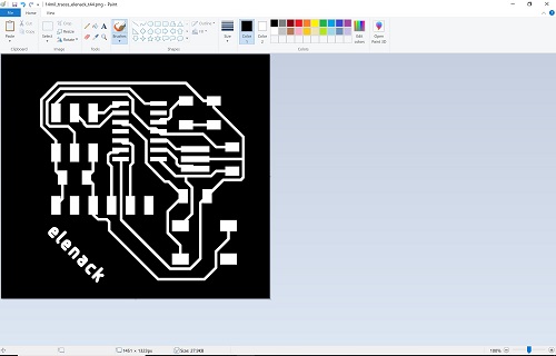
- “export image”, this will enable you to export as .png. Select Monochrome and 1000 dpi.
- “display none dim”. this will display just the dimension layer which is the outline.
- “export image”, same setting but different name (eg. outline.png).
PROBLEM 1: OUTLINE NOT SHOWING ON MODS CORRECTLY
Before my latest iteration, I ran into a lot of different design problem. One of the first one was that my outline file was not read correctly by mods.cba.mit.edu for milling.
I found an easy trick to leave a bit more margin around my board by adding a hidden layer in layer 249 shown in the image below.
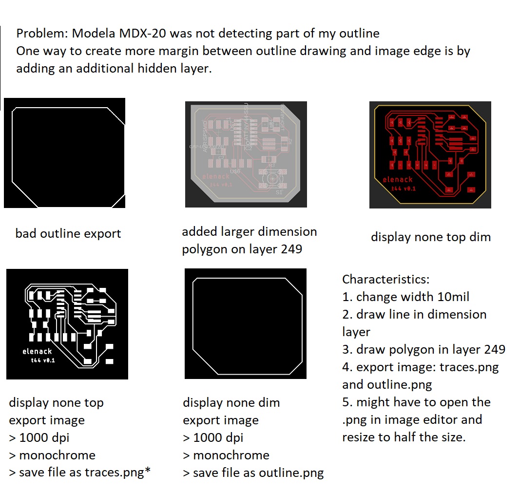
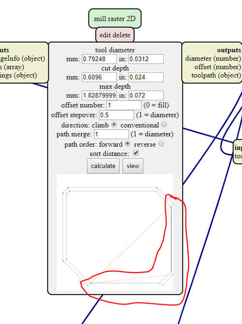
However, the machine interpreted the image as two cut, one outside the outline and one inside the outline. This is because mods interpret the change between black and white color as one cut. It will cut everything it reads from black to white color and viceversa.
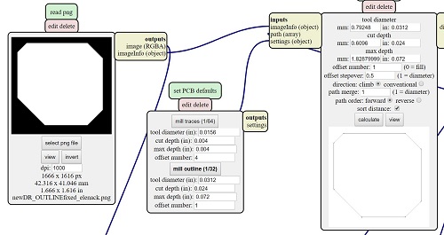
Thanks Tomás for pointing it out to me.
DESIGN RULES
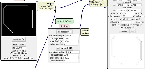
I am sharing my current DRC file (Design Rule) for the Modela MDX-20 in this blog in case I need it later. Basically, I changed the following:
- Clearance: 18mil for everything, this is the gap distance between two traces.
- Distance: 16mil.
- Sizes: 12mil, this is the width of the trace. You can go as low as 8mil (according to Tomás Vega, but the machine is doing weird stuff, so I increased it to 18mil.
- Supply: 16mil thermal isolation. This is in case you create a GND polygon plane. You should do a characterization test to figure out all of these values.
Board Milling
Once the design is one, I printed my first iteration on the Modela and figured that the board was double the size of my original design.
I also noticed that somehow, the milling is going through the board way too deep. I noticed that someone changed the mods to have a 0.04 inch depth instead of 0.004 inch in the default mods.
PROBLEM 2: WRONG IMAGE SIZE SCALING
I had to open the image in Paint software and resize the image size (scale) to (50%).
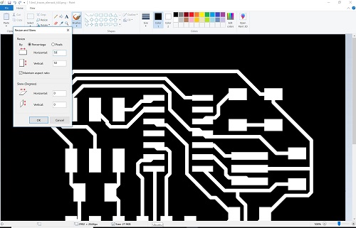
EASY FIX.
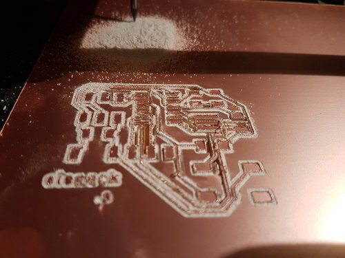
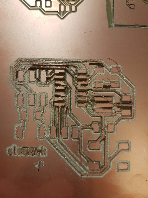
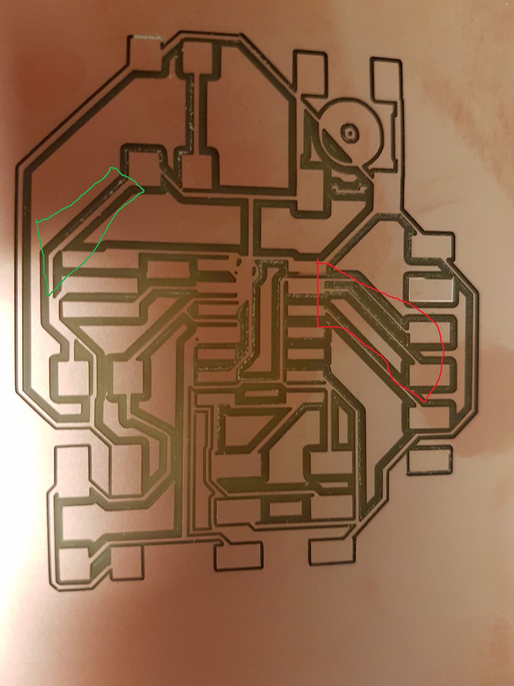
PROBLEM 3: TRACES DIFFER IN WIDTH
While I was working on my board, there were several people in the lab as well working on theirs. We all collaborated and helped each other out. One thing we figured is that for some reason, the boards were all having traces width issue besides the resizing issue. This is due to not having a flat sacrifitial layer, we noticed that it was moving a bit while it was milling and this small movement can screw up our board easily since the traces are so small.
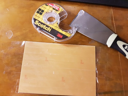
I prepared a new sacrifitial layer using double sided tape and changed the bad one.
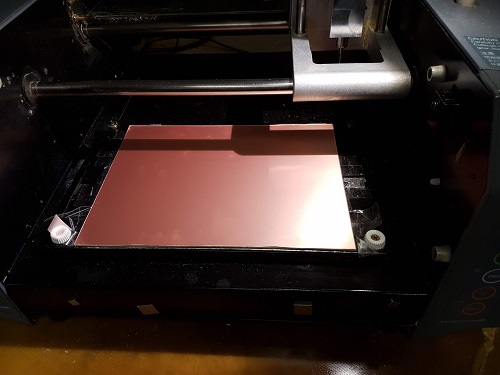
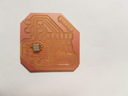
Finally, milling time!
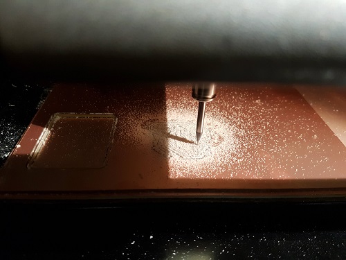
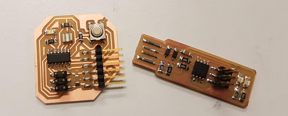
Here is the board with a soldered resonator in it.
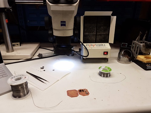
Board Soldering
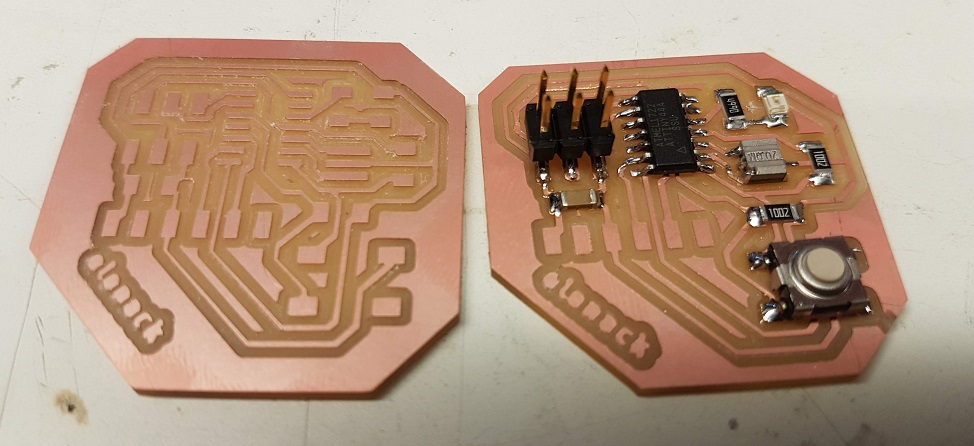
Here is the fun part, soldering. The components I used were:
- 1x 6-pin FTDI header
- 1x 6-pin ISP header
- 1x 20MHz resonater
- 1x SMD button
- 2x 10k ohm resistor
- 1x 499 ohm resistor
- 1x green SMD LED
- 1x 1uF capacitor
- 1x ATtiny44
I took the components from the E15 CBA lab to my group soldering station in E14-548 and soldered the components on one of the board.
They did not have the 6-pin FTDI header, so I soldered that later.
Board Programming
The day before, I helped Alex with programming her board on my Virtual Machine running Ubuntu. I saved all the Hello World Echo 44 files from here. You will also need to download the “term.py” file from the same site. Just use Ctrl + F and type in term.py.
LINUX
I used my windows 10 computer with virtual machine running Ubuntu to get access to Linux to do all the programming. You can follow the guide.
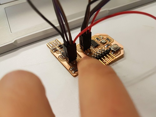
First, I connected my ATtiny45 ISP (programmer) to my ATtiny44 Hello World board (target) using the ISP headers.
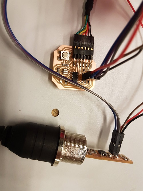
Then I connected the FTDI (usb cable) to give my ATtiny44 (target board) power.
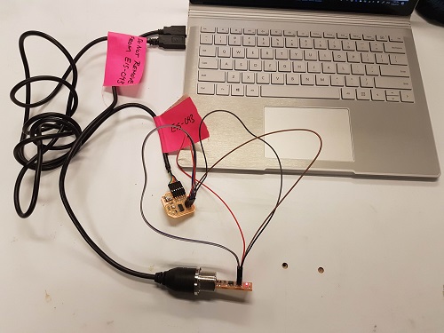
Here is a wider view of the entire connection.
After connecting everything, I ran my VM and did the programming. I had to install different packages since it was a fresh install of Ubuntu. Once you run the first line of code, it will suggest to you the packages that you need.
First cd into your directory where you saved the files. Then do the following:
make -f hello.ftdi.44.echo.c.make
sudo make -f hello.ftdi.44.echo.c.make program-usbtiny-fuses, I was using the usbtiny board to program my ATtiny44. You can do:
cat hello.ftdi.44.echo.c.make, you will see that there is option for ATMEL ICE programmer and AVR ISP as well. Read my other blog on programming the ATtiny45 to make sense of this.
make -f hello.ftdi.44.echo.c.make
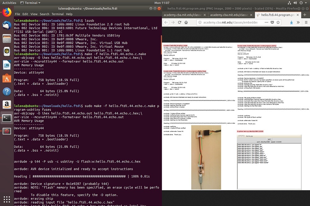
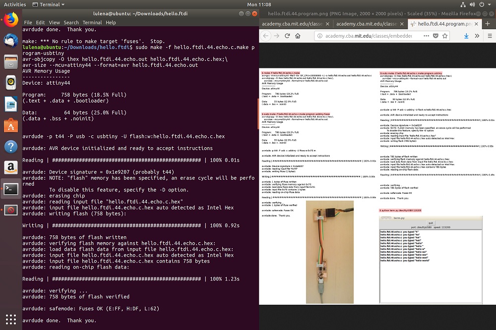
After all the setup and programming into the target board ATtiny44, it is time to test the ECHO!
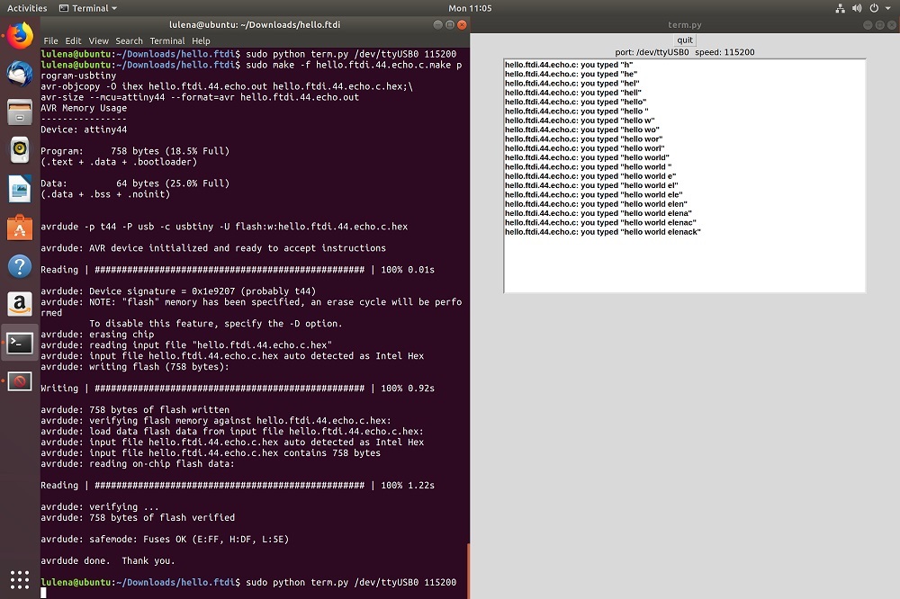
Now do: sudo python term.py /dev/ttyUSB0 115200 and a new screen should pop-up and you can type letters or words in it and it should ECHO back.
Try typing: Hello World. You can do “He” and wait for it to echo and type “llo “ and wait for it to echo again, and finish the phrase.
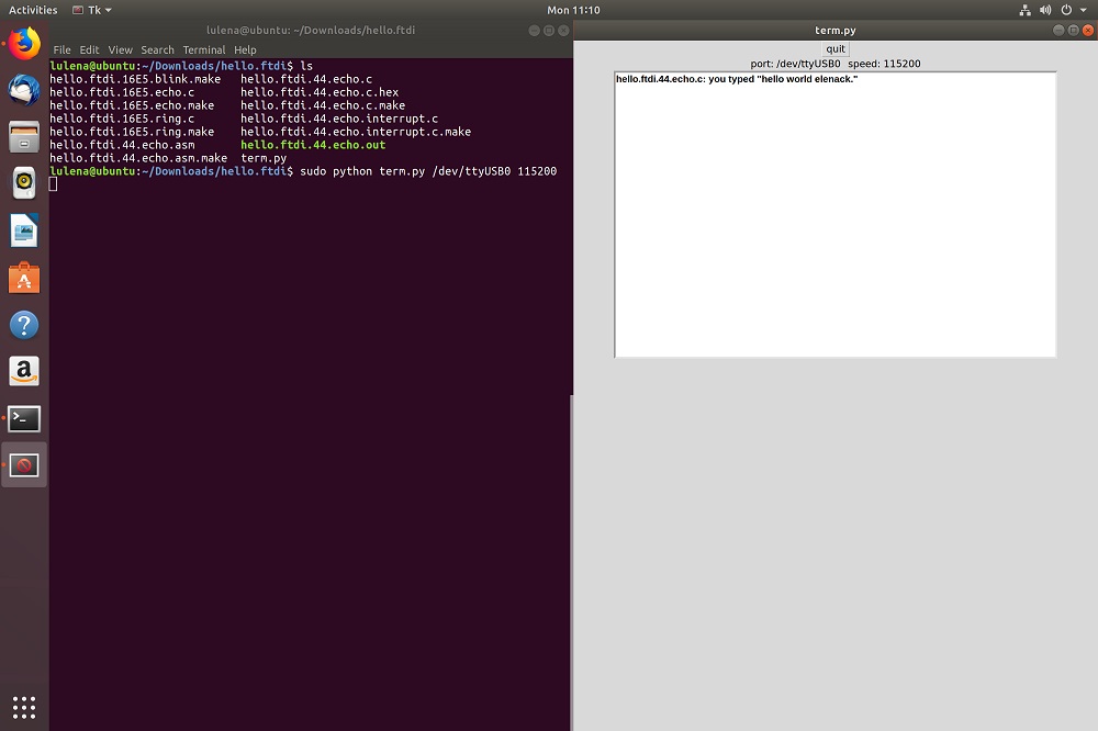
IT WORKS!!!!
POSSIBLE PROBLEM WITH PROGRAMMING
Sometimes I get the STK500 error, one way of fixing it is to add the baudrate automatically -b 115200. I am not completely sure if this is correct but it works for me. Also, sometimes you will also need to do set your COM port -P usb.
Just follow ladyada avrdude tutorial.
GOOD LUCK!