3D Milli-fluidics with Parametric Helical Topologies
week 4 (09/26 - 10/03): 3D scanning & printing
{machine: Formlabs Form2 or Stratasys Eden}
Table of Contents:
1. 3D Parametric Helical Sweeps using Fusion 360
3D Parametric Helical Sweeps using Fusion 360
So far I haven't seen any youtube videos on how to make a helical sweep as currently fusion 360 has a coil option, which allows you to make a straight coil whose length can only be adjust along its symmetry axis and not user-defined paths. So, I started looking in how to make a sweep along a user-specified path and with user-specified profile. For example lets say I want to design parametrically a circular extruded profile that rotates around a curved path. One parameter that I would like to control is the number of revolutions that the path would take around the specified path.
Below I am showing all the steps on how I achieved that.
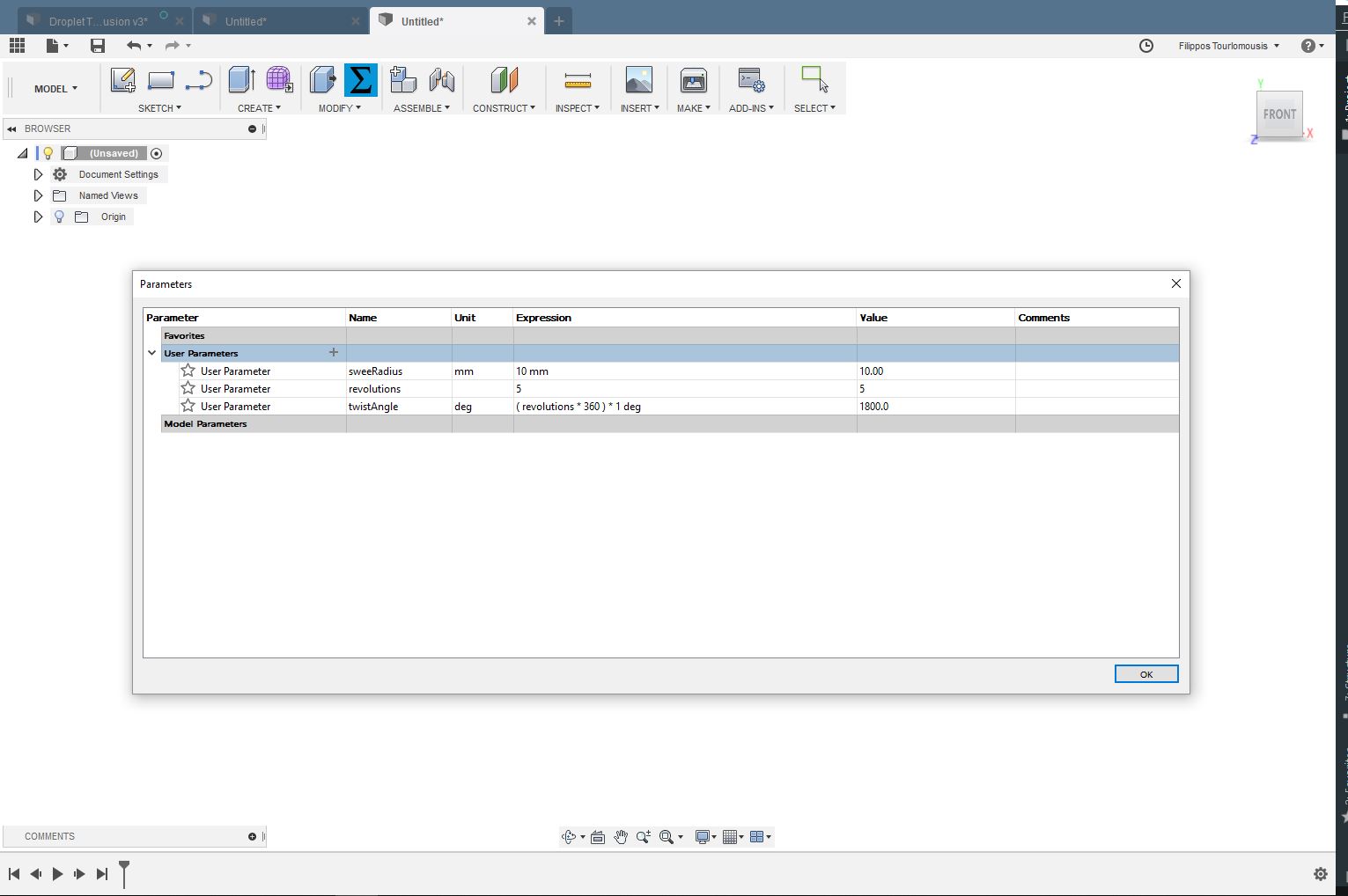
Initially, I am going to add specific parameters that control the topology of my model. To accomplish that
I click on the MODIFY tab and then on Change Parameters option. A window pops up that allows
me to enter the parameter name, unit and expression by filling in the Name, Unit and
Expression fields, respectively. The parameters that I added are the following:
sweepRadius: 10 mm
revolutions: 1
twistAngle: Revolutions*360
Now, I create a new component by clicking on the Component tab and then I create a sketch on the front plane. Within that sketch I draw the path that my extruded profile is going to be moving/rotating along using the tools under the SKETCH tab. Please note that the path can have whatever topology you want without sharp edges. A good advice is that you should try to make your sketch fully constrained by adding dimensions and constraints. Off course, you can always make it parametric as well by adding each dimension as a separate parameter following the steps previously described.
After completing our path, the next thing I am going to do is to create the initial sweep. To do that , I click on the CONSTRUCT tab and then on the Plane Along a Path option. Then, I select the sketched path and set the Distance field value to zero so that extruded profile can start form the beginning of the path. Then, I create a sketch on the previously constructed plane. This sketch has 2 lines. The first line is a construction line perpendicular to the path starting point whose dimension I set it to be equal to the sweepRadius parameter. The second line I draw it with a starting point from the end point of the previously sketched construction line and I set its dimension equal to 5 mm.
Now we are ready to create our sweep. To accomplish that, I click on the MODEL tab living on the top left corner and then on the PATCH option. This takes us to the "patch environment" where we have access to some very cool extra options/commands relate to sweep. By pressing the letter s on our keyboard, a menu pops-up, where we can type sweep. A window pops-up with following fields: Profile and Path. For the profile I choose the line (not the construction line) and for path field I choose the very first two line segments I sketched.
Continuing within the Patch environment, I create a sketch in the Front Plane.Now, under the SKETCH tab I click on the Project/Include option and then the Include 3D Geometry option. Then, I click on the inner line (the line whose distance from the path is equal to sweepRadius) of the extruded profile. To get the whole extruded profile, we need to click to both line segments.
After that, I stop the sketch and then I need to set the path for twisting extrude profile. To do that, I click on the CONSTRUCT tab and then on the Plane Along a Path. This allows me to choose the twisted extruded profile and a plane perpendicular to this is created at the distance I want across the chosen profile (do not forget move the plane to the starting by grabbing the blue arrow).
Going back to the modeling enviroment, I create a sketch on the previsouly formed construction plane that will define the cross-sectional profile shape that is extruded. I draw a circle with a diameter equal to 5 mmm:
Lastly, I stop the sketch and as before I press the letter "s" on keyboard and then Sweep. I choose the sketched circle and I get my helical sweep rotating around the initially drawn path! Lets experiment by simply changing the the 2 main parameters governing our spline topology! Can you fabricate that using milling? NO! Below are a couple of helical 3D structures for different values of sweepRadius and revolutions: