Output Devices
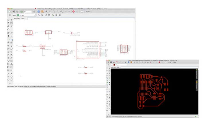
This week’s assignment was to add an output device to a microcontroller board I have designed, and program it to do something. I decided to work with the tiny LCD display as it could be helpful for my final project. Considering Neil’s board example, I have followed the steps done in week 5 to design a board from scratch in Eagle. However this week I haven't added any new components to the board, but have redesigned the schematic and the board layout.
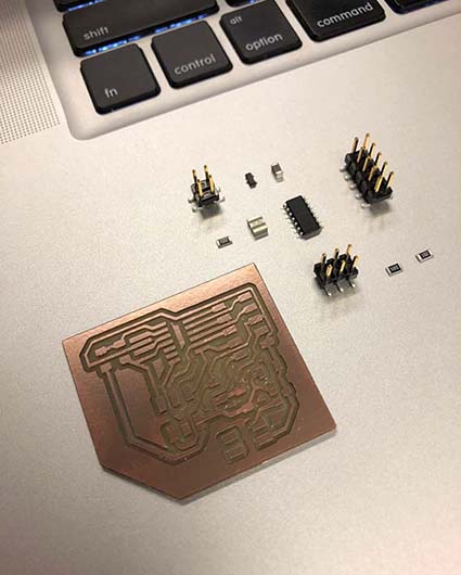
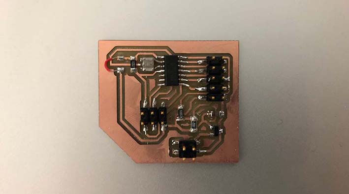
As last week, for this week's board I have used a jumper to connect two components of the board. Apparently milling and soldering worked without major issues this week. To solder the bridge, I have used a coated wire, have exposed its pits using pliers, so that the conductive part could be directly soldered to the board. It was important to solder carefully, since the coating material is kind of sensitive and can be very easily melted when close to the solder’s heat.
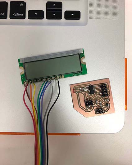
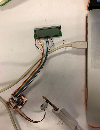
With the board done, I had to solder the rainbow coloured cable to the LCD display, but unfortunately one of the solder machines from E15-40E stopped working, while the other one was being used by another student. unfortunately I could not get the cable soldered on time before class. As an attempt I have tried to wrap the wires of the cable around the connectios of the LCD board, although I knew this was a kind of guerilla attempt and that it probably would not work.
After having wraped the wires around the connections, I have followed the steps done in week 7 for Embedded Programming, however using specific ‘make’ and ‘c’ files to program the LCD display, downloaded from the class website.
same steps as done in week 7:
- connect the usbtiny to your computer using an usb cable
- connect the ISP header from the board to the ISP of the usbtiny in the right orientation using the rainbow cable (check the orientation looking at your board layout: vcc should connect to vcc)
- in your computer create a new folder, called LCD
- Save both files: c + makefile at your new folder (if using Neil’s code, both are available at the course website under this week's assigment)
- Be sure to rename the makefile file as makefile in case it has any different name
- In terminal enter 'cd' , than drag the just created folder to terminal after typing cd
- Open the makefile for a check up
- In terminal enter >> make
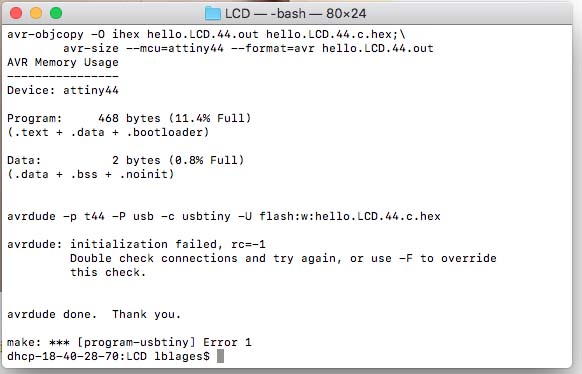
- In terminal enter >> sudo make program-usbtiny
- In terminal enter >> sudo make program-usbtiny-fuses
I have followed this same steps, but got stuck in the 3th step 'sudo make program-usbtiny', to which I got the error 1 message. I was unsure if I was getting this error because of some missconnection in my board itself, or because of the improvised connection between the rainbow cable and the LCD. Hope I can figure this out in the coming weeks.
This week’s assignment was to add an output device to a microcontroller board I have designed, and program it to do something. I decided to work with the tiny LCD display as it could be helpful for my final project. Considering Neil’s board example, I have followed the steps done in week 5 to design a board from scratch in Eagle. However this week I haven't added any new components to the board, but have redesigned the schematic and the board layout.
As last week, for this week's board I have used a jumper to connect two components of the board. Apparently milling and soldering worked without major issues this week. To solder the bridge, I have used a coated wire, have exposed its pits using pliers, so that the conductive part could be directly soldered to the board. It was important to solder carefully, since the coating material is kind of sensitive and can be very easily melted when close to the solder’s heat.
With the board done, I had to solder the rainbow coloured cable to the LCD display, but unfortunately one of the solder machines from E15-40E stopped working, while the other one was being used by another student. unfortunately I could not get the cable soldered on time before class. As an attempt I have tried to wrap the wires of the cable around the connectios of the LCD board, although I knew this was a kind of guerilla attempt and that it probably would not work.
After having wraped the wires around the connections, I have followed the steps done in week 7 for Embedded Programming, however using specific ‘make’ and ‘c’ files to program the LCD display, downloaded from the class website.
same steps as done in week 7:
- connect the usbtiny to your computer using an usb cable
- connect the ISP header from the board to the ISP of the usbtiny in the right orientation using the rainbow cable (check the orientation looking at your board layout: vcc should connect to vcc)
- in your computer create a new folder, called LCD
- Save both files: c + makefile at your new folder (if using Neil’s code, both are available at the course website under this week's assigment)
- Be sure to rename the makefile file as makefile in case it has any different name
- In terminal enter 'cd' , than drag the just created folder to terminal after typing cd
- Open the makefile for a check up
- In terminal enter >> make
- In terminal enter >> sudo make program-usbtiny
- In terminal enter >> sudo make program-usbtiny-fuses
I have followed this same steps, but got stuck in the 3th step 'sudo make program-usbtiny', to which I got the error 1 message. I was unsure if I was getting this error because of some missconnection in my board itself, or because of the improvised connection between the rainbow cable and the LCD. Hope I can figure this out in the coming weeks.