Final Project:
A TERRARIUM FOR DECAY
What does it do?I made a terrarium filled with rain water, soil, decaying bananas and a fruit fly colony, whose temperature and humidity is being monitor using a sensor and sent to my computer remotely. A long durational timelapse will be set up to monitor the process of decay and growth within the enclosed system
Who's done it before hand? There is a long history of the use of clear glass or perspex cubes as part of artistic intervetions and strategies. Immediately to mind come Hans Haacke's Condensation Cube, Walead Beshty's Fedex Boxes, and museological displays. I designed a perspex box, a board, a sensor.
Materials and Components: Perspex, Acrilyc Cement, Fabduino Board and its respective components ( ATMEGA 328p, Crystal resonator, 22pF capacitor, 2 LEDS, various Pins, and pads, a push button, resistors ), Temperature and Humidity sensor, Soil, Bananas, Fruit Fly Colony, A Piezo sensor, Audio Cable, Tape, Raspberry Pi, Raspberry PI Camera Module.
Components all came for the lab except for the humidity sensor which cost approx $3 from adafruit. Everything else came from the Lab or ACT studio library.
Cost of Materials:
Acrilyc Sheet 24 x 36: $14
Dirt, Bananas: Free
Humidity Sensor: $3
AT MEGA: $2.87
Crystal: $.50
Capacitor 10 pf (4) $.16
Resistors x 4 : $.04
Headers $.89
Rasberry Pi: $35.00
Rasberry Pi Cam Module: $25
TOTAL: $81.66
Parts and Systems made: Fabduino Board, Perspex Cube.
Processes Used: 2d Design for perspex box, Electronics design for Fabduino, 3D Design for protptyping, Laser Cutting, Programming for Arduino, Inputs and Outputs for sensor reading.
Questions Answered: In this process I learned alot about dealing with electronics in a more functional way, how to choose according to your needs versus recreating a board for its own sake. I learned also about prioritizing and instead of attempting somethign overly ambitious, I accomplished a personal goal of getting at least one electronic input and boards to work, which I hadn't managed to do all semester. I was able to complete one small thing I had set out for myself and use it for my own studio practice.
How was it evaluated: Personal reference and my own slow but steady progress in this class. It wasn't what I hoped for but I have some avenues and hopes for future projects I didnt have before.
Implications: For myself, it means a new entrypoint into technologies I was intimidated by, for greater implications this project is also an experiment in closed systems and different modes of sensing. Notice the beautiful drawings and patterns in the condensed rain water created by the larvae of the fruit fly.
Initial Ideas -
For my final project, I hope to let the upcoming weeks guide me in a better direction and to better know the limitations of the media and materials I am working with. I have been working mostly with analogue modes of photography, drawing and sculpture, and looking further at other forms of image making. Surveillance and GIS technologies are of particular interest to me so I'm curious to see if this could be an avenue to explore that.
I'm interested in the ways in which vision, technology, vision and the imaginary intersect with power. I have been looking at reocurring forms in which cameras, or different apparatuses to extend vision have been deployed as tools that replicate mechanisms of coloniality.
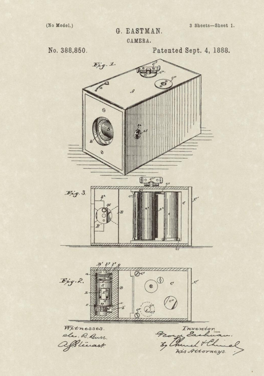
My previous experience as a photographer has biased me towards cameras, but I wonder if this could be challenged or expanded in different ways. In what other ways is the potentiality of vision expanded through technology? What are the material and ethical consequences of their deployment?
UPDATE
Thinking about surveillance technology through which processes of power projection and force protection. How this is deployed in places like Honduras to enforce and protect an existing power structure.
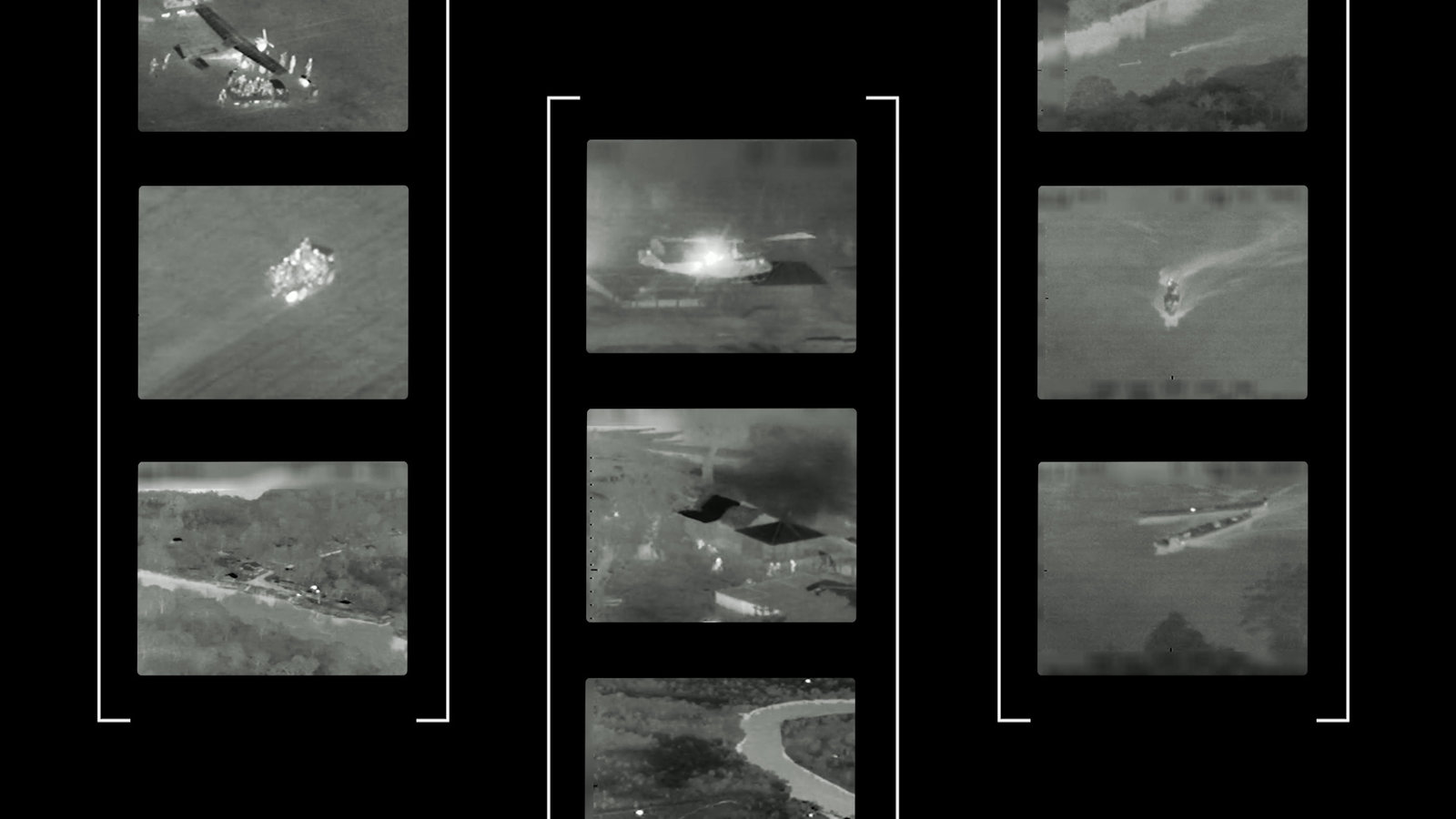
Video of DEA Strike in La Moskitia, Honduras.
I was thinking about these technologies and if they could be used to subvert these existing power structures, So I started looking for accessible versions of them.
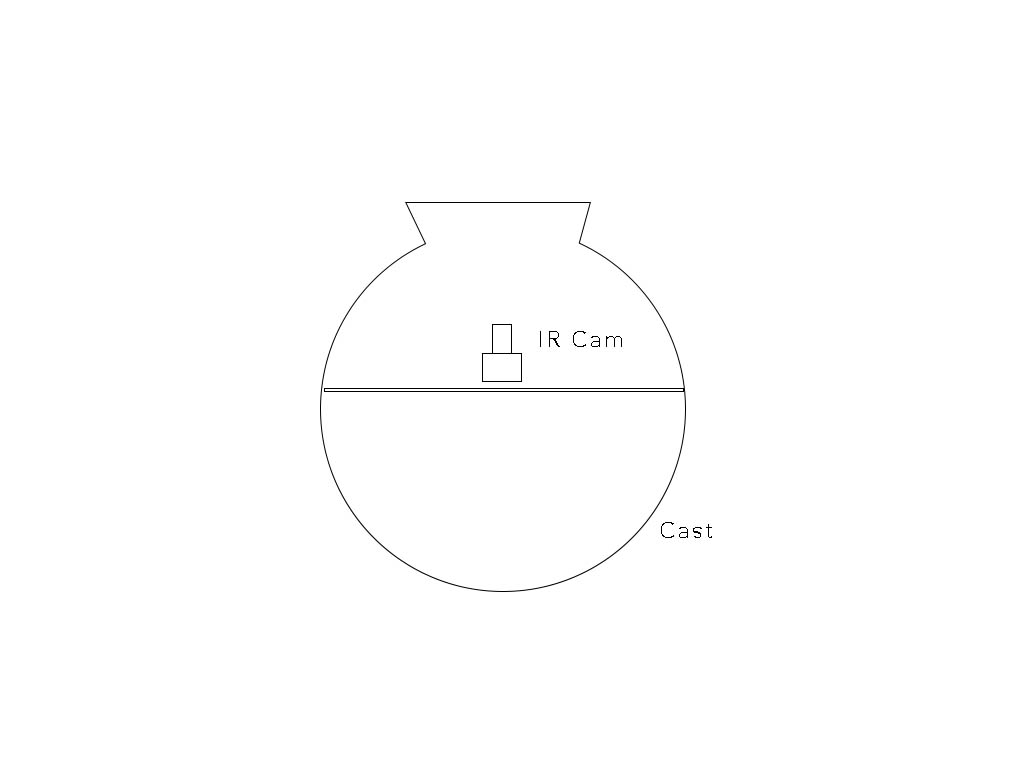
In a version that might be more symbolic, I would like to create several infrared cameras made out of vessels, and locate them in places around the city where surveillance happens in everyday, maybe public or institutional spaces. thinking about developing this idea more later.
TERRARIUM FOR DECAY:
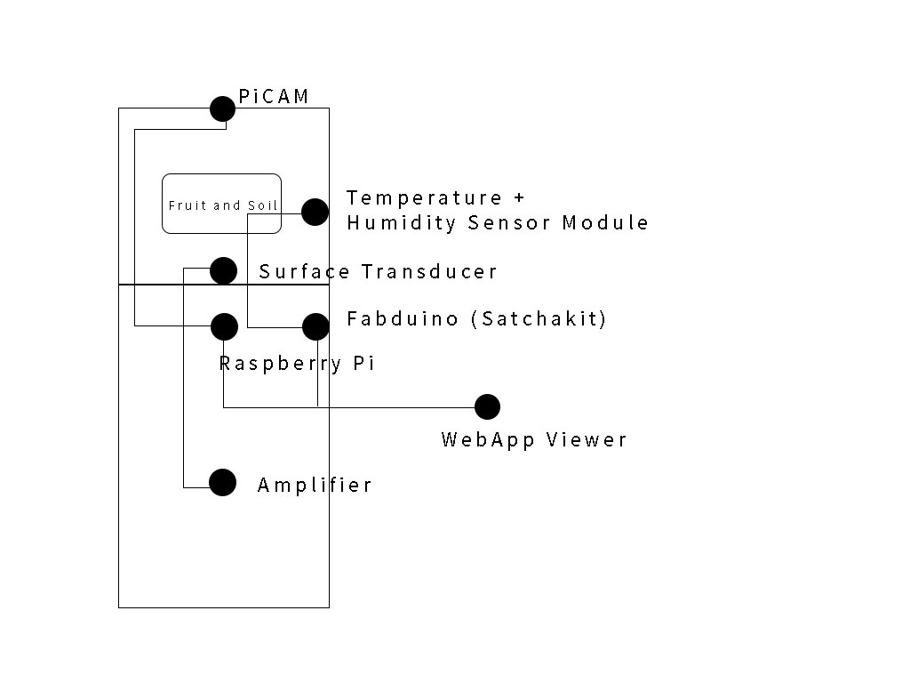
I've been thinking about ways to include my studio practice into the things I am doing for HTMAA. Integrating and planning for this has been a challenge but I finally came up with a system that I might be able to accomplish.It would essentially become a terrarium made of acrilic glass, where you can time and monitor the process of decay using acoustic, visual, and sensory information. By this I mean an audio output, a camera output, and temperature and humidity sensor.
INPUT DEVICE
Using a raspberry pi and a PiCam for Input devices, I was able to set up a raspberry pi and camera module. The process is pretty straighforward, and involves connecting the camera module and running a series of simple commands:
From the terminal run:
"sudo raspi-config"
If the "camera" option is not listed run
"sudo apt-get update" and "sudo apt-get upgrade"
Run "sudo raspi-config" again - you should now see the "camera" option.
BOARDS AND ELECTRONICS:
This week I attempted to mill a SatchaKIT board as a test for future. You can follow the instructions closely and attempt yourself to make the board. However I encountered some issues with milling the thin traces on the ATMEGA 238p. I had to create some bridges while soldering and I hope this will work.
I ended up creating the board, but instead of milling the vias, used ftdi headers pins. I had some issues with the ground and VCC and had to create large pads for them to connect but I did not run into issues of shorting when I checked.
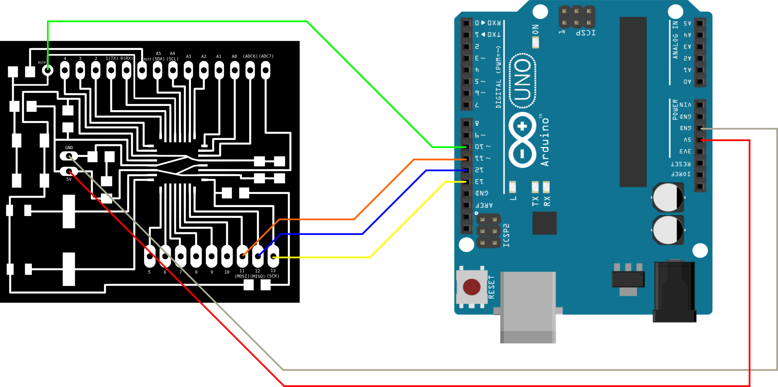
After not having much luck programming the boards in C. I decided to program using the arduino IDE. This turned out to be both a blessing and a nightmare. On the one hand, I was able to understand better the process of creating your own board and using an arduino as a programmer, on the other, it came ith a set of issues that I didn't anticipate. I will attempt to discuss here my process for making the SatchaKit using the bootloader and what didn't work. First I attempted to program with the Adafruit Metro which I configured as a programmer using the IDE.
Under Tools>Board select Adafruit Metro, and below under Tools >Programmer>Select Arduino as ISP.
Under Sketches, I loaded the Sketch called Arduino ISP onto the metro and then proceeded to pin the Fabduino Board. The Metro seemed to recognize the board, as they were both blinking simultaneously which I considered a good sign. Now on to the next step, which is running the Bootloader.
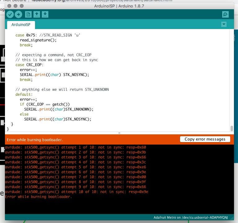
This turned out to be the most frustrating step, as I kept getting the following error. This happened because initially I loaded the ArduinoISP sketch onto the board itself, so make sure your board is unplugged from the Arduino before loading the ISP and then attempt burning the bootloader.
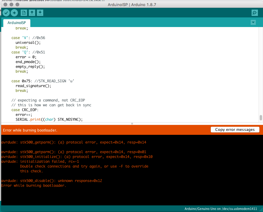
The next attempt I got the following error. ( Basically RC-1) which means, the board isn't being read. However, the lights were simultaneously blinking, and after sending a basic blink without delay sketch, I realized the boards were communicating.
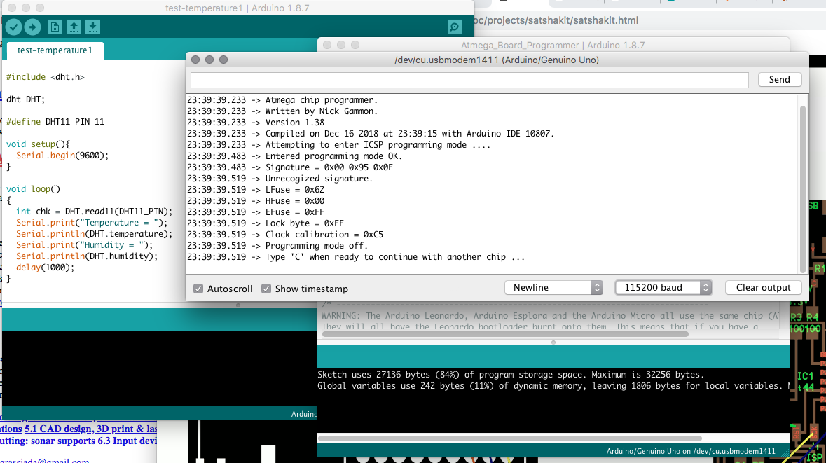
I was able to finally program the board following this incredibly helpful tutorial by NIccolo Gnecci from Fab academy, essentially using a sketch to burn a bootloader. When running this operation make sure Baud Rate is set to 115200. After downloading the sketches from GIT LAB, I was able to run the sketch and follow the prompts to burn my bootloader after much head scratching and hysterical crying.

---
TEMPERATURE SENSOR: INPUTS
So currently my temperature sensor situation isn't great, however I used the DHT11 HUMIDITY SENSOR to connect to the fabduino which presented its own set of challenges. I realized this fabduino does NOT have an extra 5 V output and Ground pin for me to connect to the board. I had to use a breadboard to make the connections with my sensor work, after much trial and error. Unfortunately, due to time constraints, I could not mill a board for all my connections. So I made do with a prefab board and some creative soldering.
I was finally able to get readings from it into the Arduino Serial monitor so I am quite happy, as it is the first time I could get data at all.

AUDIO:
For this component of my piece, I am using an analogue touch microphone which is plugged into an AMP. This is quite fun, as it is able to pick up on sublte vibrations and translate them into sound. Making it involved using a piezo surface transducer and an old audio jack cable cut and stripped to expose the wire. From here you just connect ground and VCC respectively, then solder and heat wrap the cables to protect from the humidity inside the surface.
ENCLOSURE:
I used a very simple design for the box. Just a pressfit acrilyc box laser cut and then glued together. SVG File can be found here.

Overall this project wasn't an entire success in the sense that it didnt achieve all the goals I set out for it. I wasn't able to integrate all the inputs into software (the camera and the sensor) as I had hoped, since I spent largely the bulk of my time struggling with the fabduino board. Nonetheless it was wonderful that things that had not worked befure in class, actually did for it. I was able to program a board, mill it, repair it ( It BROKE ON MY WAY TO THE PRESENTATION ), successfully read an input from a sensor from the arduino serial monitor. It's my hope to revisit this project and keep working on it for the rest of the semester!