Week 13
Networking and Communications

Assignment:
1) Design, build and connect a wired or wireless node(s) with network or bus addresses.
2) Send a message between two projects.
This week I chose to pick a relatively easy project because networking is new to me (= better chance of making something work.) I remade Neil's Serial Bus RS-232 board. I got a little ambitious this week by trying a new board fabrication technique, using the vinyl cutter to make traces instead of the Roland mill. Huge thanks to Oceane and Liz for teaching us what they've learned about board fab using the vinyl cutter!
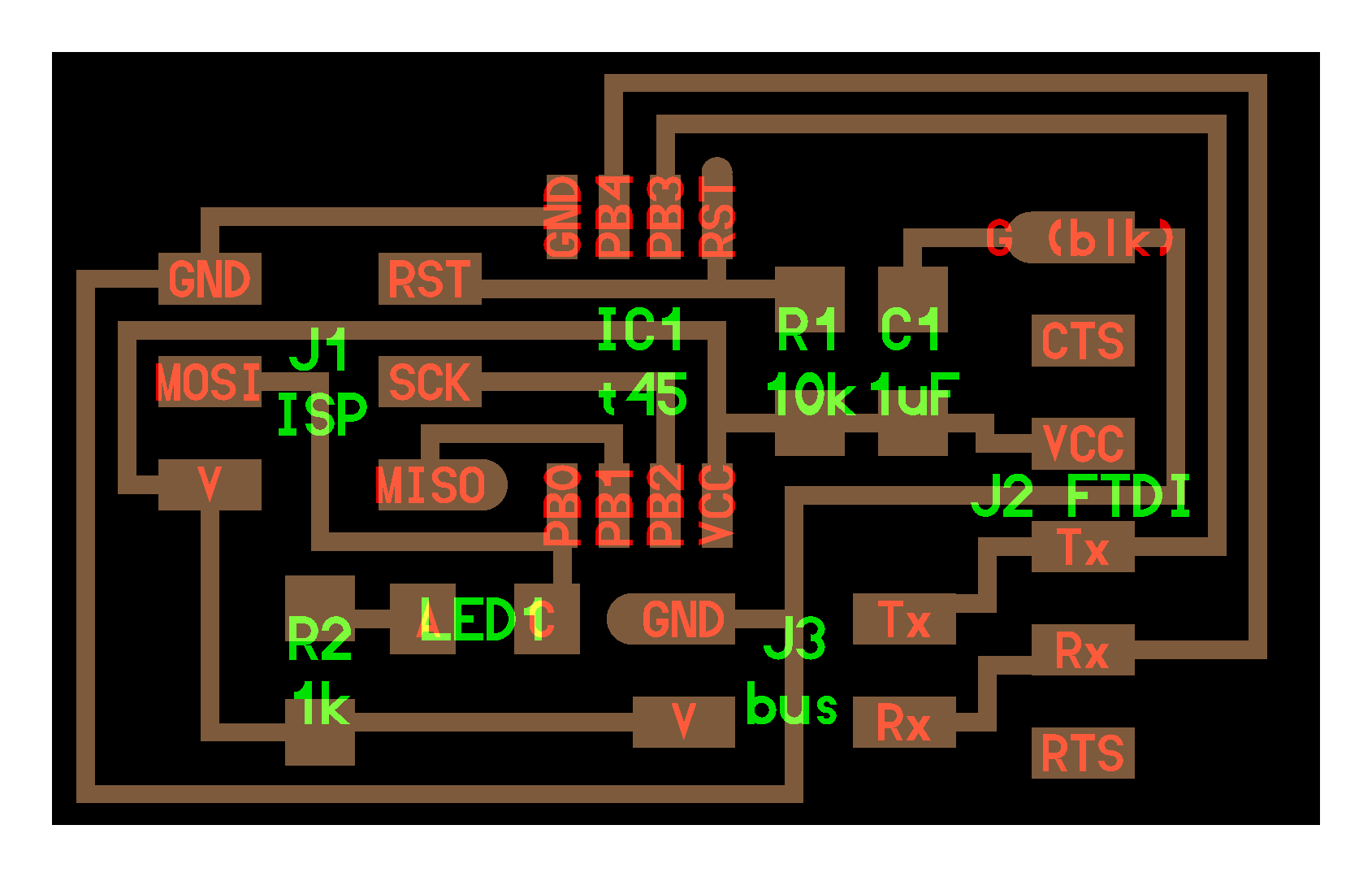
Neil's board
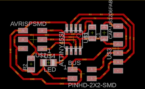
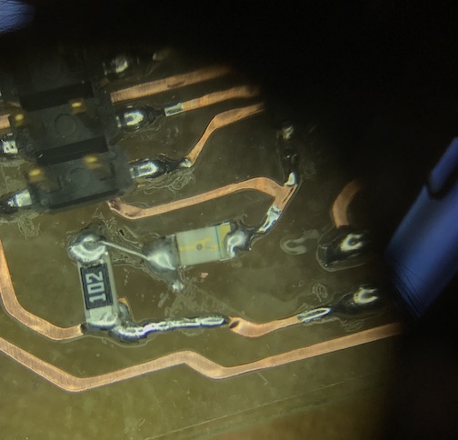
My board
I designed my board with slightly wider traces, to help keep them from breaking during the vinyl cutting and weeding process. I used a width of 18 mills and a clearance of 12 mills. To use the vinyl cutter, export your Eagle board file in black and white, as per usual. Open it on the computer attached to the vinyl cutter. Eagle will export a PNG file, which you need to convert to SVG. You can do this on the vinyl cutter's computer by going to fabmodules.org and using the built-in image converter feature. Calculate your traces, then save as an svg and open in Corel Draw.
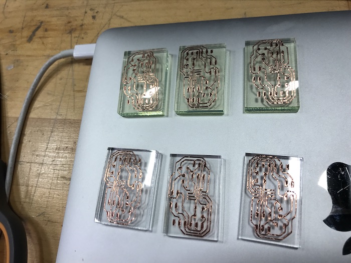
You'll need to prepare the copper for the vinyl cutter. We used a sheet of clear acetate, and a sheet of copper with sticky backing that we laid over the acetate, taking care to lay it out very smooth. I smoothed the sheet even further by using a soft scraper/putty knife type tool, with a sheet of paper towel in between that and the copper so I wouldn't scratch the copper. Then, I trimmed the sheet with scissors and put it in the vinyl cutter, and had the vinyl cutter measure the sheet. I used the pre-set cutting speed of 20 and force of 80.
My first viny cut looked ok, except.....really big. I realized that the image file probably needed to be resized after being exported from my macbook, due to the known issue with macbooks that have retina displays exporting double-size images.
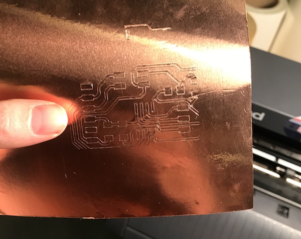
I resized the image to 50% in Corel and tried printing again. This worked, except that the print area between the wheels that hold down the paper wasn't wide enough for my image, and so the left-hand side was cut off. I retried with a bigger sheet of copper, which worked perfectly.
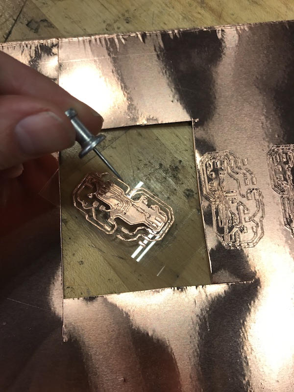
Next step is weeding the copper to pull away everything but the traces. This was pretty straightforward, except on a few tight corners which required some finesse. Since there were no sharp tweezers available I used a pushpin to begin separating copper pieces, and finished pulling it up by hand. This worked fairly well.
To make a base layer for my traces, I measured the size of my board and cut squares out of scrap acrylic using the laser cutter. This was easy and generated only a small amount of occasional flame and no fires.
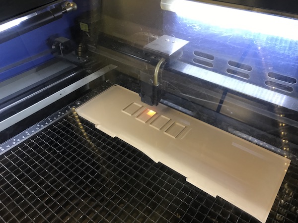
Here are the settings I used to cut 1/4 inch acrylic on the laser cutter: Speed = 1.7, Power = 100, PPI = 400. This was run twice over the same spot to make a full, clean cut. Next, I superglued the vinyl-cut traces onto the blocks.
Stuffing the boards
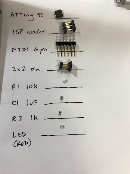
Here are my board components.
Soldering onto the acrylic was harder than soldering onto a regular board. The acrylic will start to melt quickly when exposed to heat. To help things along I tinned the pads, which means that I first put solder down on the copper bits that I planned to add components to. The problem here is that the solder bunched up into balls, which made resting the components on top difficult, as they would slide off. It usually helped to hold the part in place with tweezers while re-melting the tinned pad a bit to get it to stick to the part.
Programming
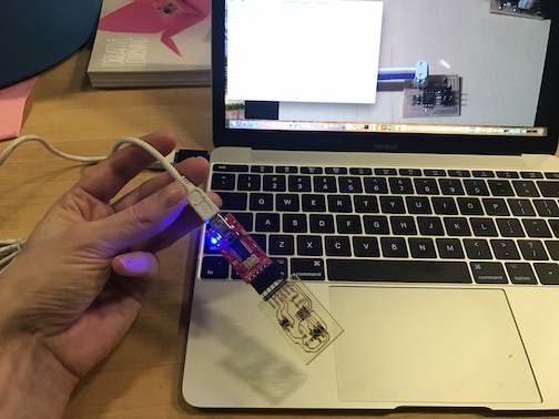
I connected my board to my laptop using the Atmel programming and some adapters. My first attempt at programming the board gave me this error. Notably, "double-check connection and try again" and "bad response to AVR sign-on command.
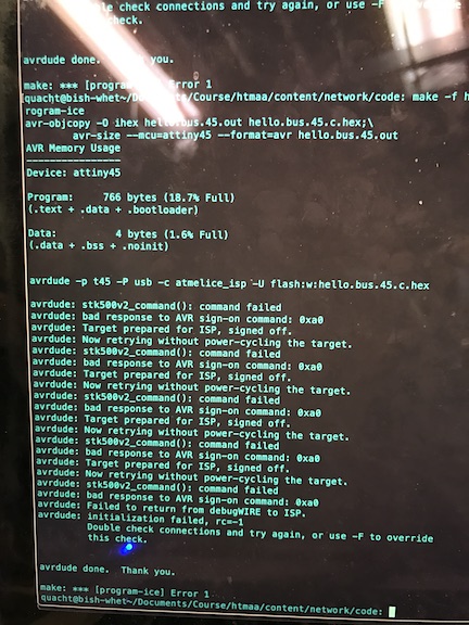
I connected my board to my laptop using the Atmel programming and some adapters. My first attempt at programming the board gave me this error. Notably, "double-check connection and try again" and "bad response to AVR sign-on command. A little Googling indicated that one of the errors that showed up might be a compatability-with-macbook issue. I tried programming on a friend's computer but still received the errors. After receiving the dreaded RC=-1 hardware error message, some closer inspection revealed errors in my Eagle board design. Note: don't rush your board design, particularly if you have a migraine at the time. I had used the same label for too many connections, and so had made a few wrong connections.
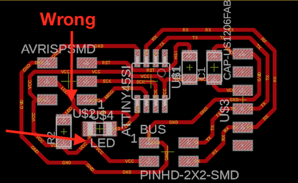
The LED trace and the resistor were incorrectly routed. I did some surgery on my board to fix this. I broke the connection and re-routed and soldered the trace using a small jumper wire. This is, I suppose, an advantage of making flexible traces with the vinyl cutter.
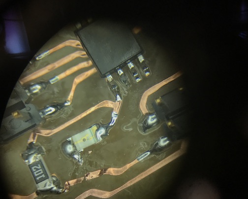
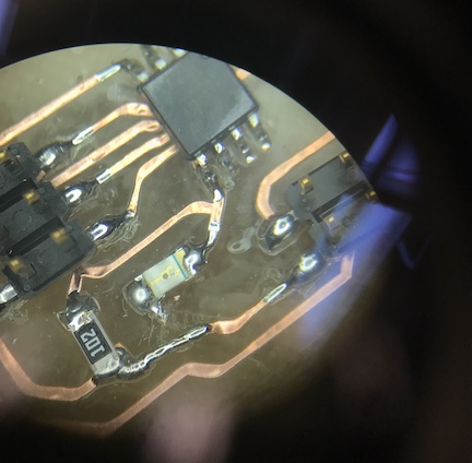
I then tried to program the board again and got the same error. Another review of the schematic revealed another routing error: I'd accidentally used the name "LED" for a trace that went to "MOSI" and so I had incorrectly routed both. I fixed this too, tried programming again, and this time it worked!
Team project
Tina and I connected our boards as three nodes in a communications network. We gave each node an address (Node 1, Node 2, Node 3) and had the boards communicate and flash their LEDs. It worked!