Week 5
Designing, making and programming a circuit board
Assignment:
1) Design a circuit board, using a list of given parts
2) Print and stuff the board
3) Program the board
Where do I even begin describing what went wrong this week. It feels like everything. I couldn't find the right parts in the parts library. I later found out that I picked some incorrect parts. I had a tough a time designing my board in Eagle at all and ended up doing 3 iterations. I failed to do a number of things that Eagle, the PCB design software, requires you to do. For example, when I connected the parts on my board with traces, I didn't see that the traces are supposed to connect to a hard to see small yellow trace that pops up at the center of a part when you hover over it. Given this, many of my parts were not properly connected.
First design attempt
Third design attempt, before drawing traces

Third design attempt
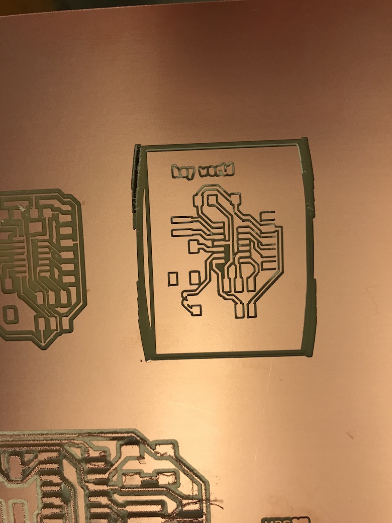
I had issues drawing the border around my board design, which resulted in this improperly cut border (as well as some incompletely cut traces):
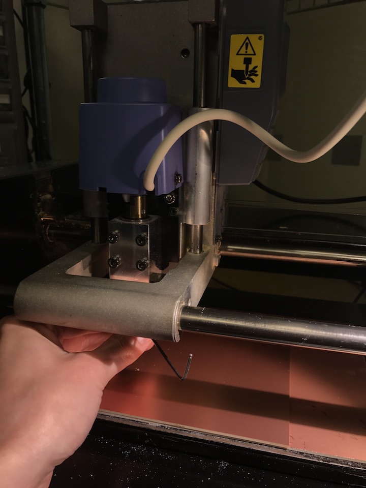
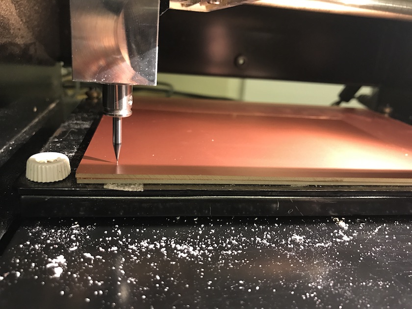
Inititally, I couldn't get anything at all to mill on the MDX-20.
Everytime, the machine would just cut into the air. I tried restarting the computer and the machine, and resetting the origin and the z-height, many times. Finally, I figured out that whoever had set the sacrificial base layer of copper on the machine had done a poor job taping it down. This was causing the base to stick up a bit, so every time I zeroed the needle, it was getting an inaccurately high reading. When it tried to cut, the copper would get pushed down to the base, but the needle would stay high, so nothing was cut.
Adjusting the z-height on the needle
Before I could replace the copper and base layer, I had to find more copper as the shop room ran out. Thankfully Tomás was in and showed me how to cut new copper.
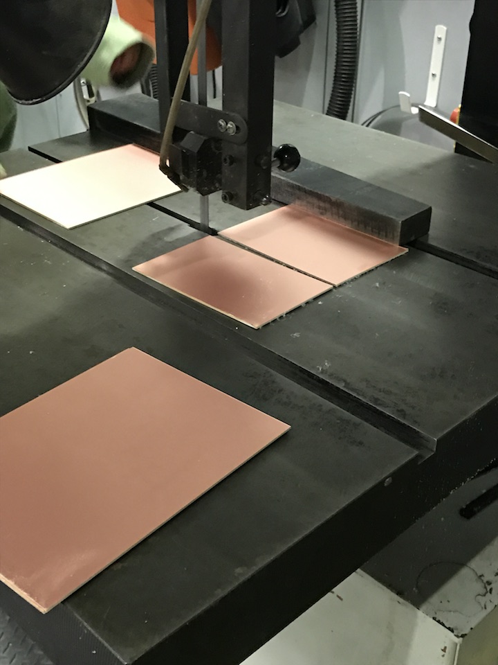
Cutting more copper.
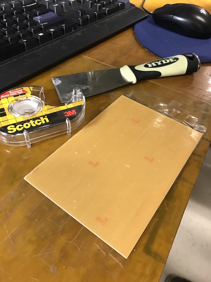
Taping new copper and base layer.
New clean copper, ready to go.
I was also getting this status error a lot in Mods ("cant's send, not op[erational]"), which prevented me from sending anything to the MDX-20:
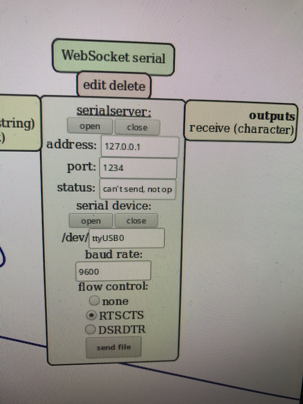
Fiddling with the USB cable connections between the computer and the MDX-20, and restarting all programs and the MDX-20, seemed to fix this particular error.
My first board printed with incomplete traces, and was unlikely to work
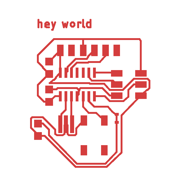
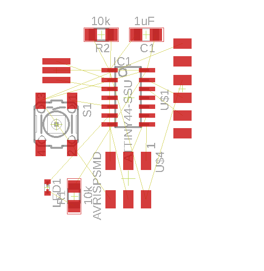
I went back to the literal drawing board, remaking my board in Eagle. This time, I set all the traces to be wider, at 16 mills. I also added a dimension for thermal isolation (10 mills), which will keep the traces far enough away from each other that they can have a clean delineation. I drew my traces with more exacting standards, maing sure nothing was too close to anything else. last time, I had been getting error messages during the Design Rule Check stage about parts overlapping.
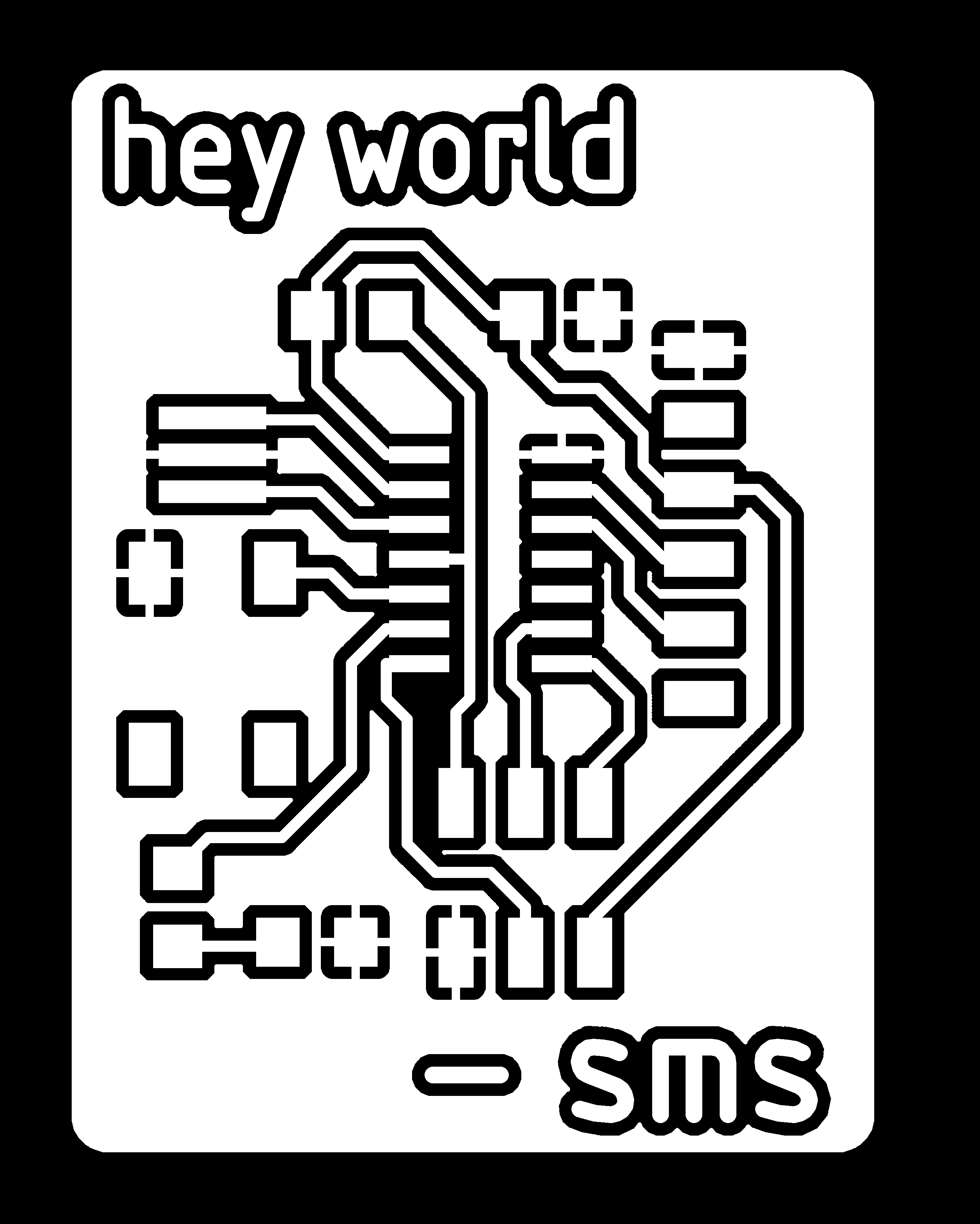
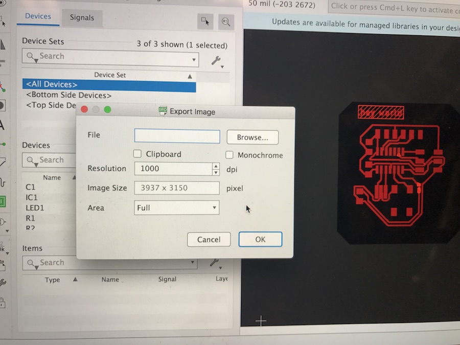
New board design.
I had issues with my board dimensions. Initially, MODS saw my board as being over a foot wide.
I think there may have been an issue with my earlier board design, where I didn't draw the cut border correctly, and so MODS thought that my board was the size of the entire design field in Eagle (eg, my border didn't export correctly). Redrawing my board and outline seemed to fix this.
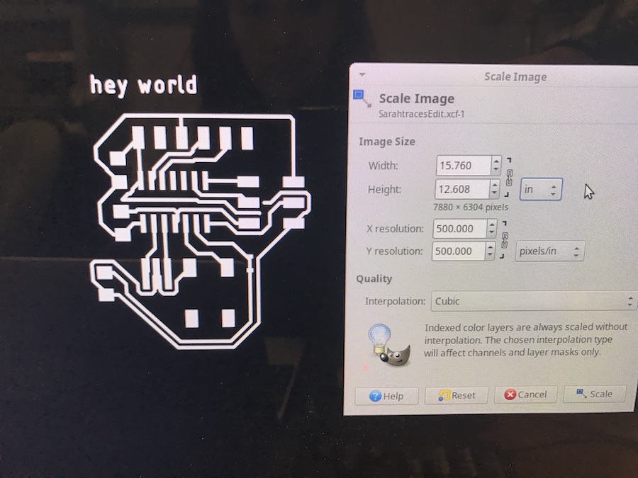
Our class was also warned about exporting files from Macs with Retina displays, as the files would be twice as big as they should be. I have a Mac Retina, but I mis-read the Gitlab issue about this, so I wasted a lot of time doubling and halving the dpi. Apparently, the DPI shoudl stay constant. It should be whatever it is when you initially make your file in Eagle. After you export your PNG files for your board, but before you load them into MODS, you should open your PNG file in a photo editor (I used GIMP) and resize your image to be half its size. So, if your image is 4 inches wide, make it 2 inches wide. Keep your image to scale.
Another way to tell if your image is the right size, is to go into your board design in Eagle and use the measuring tool (called "dimension"). With that, you can directly measure the length and width of your board. Check that the PNG file you are loaing into MODS shows the same dimensions. Do this before you print, if you are unsure about your print size. It's important that the print size be accurate, because if it isn't, your parts will not fit on the board properly when you get to the soldering stage.
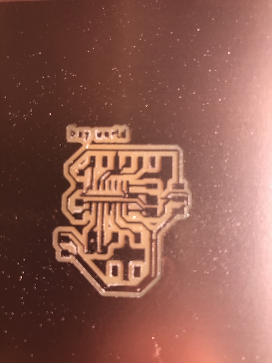
Finally, after perhaps 20 hours, I was able to print a board.
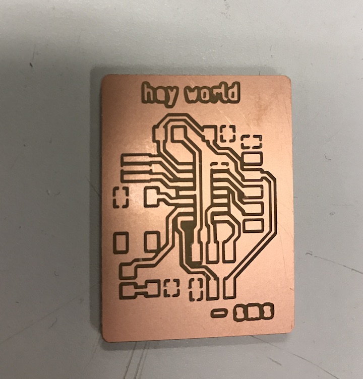
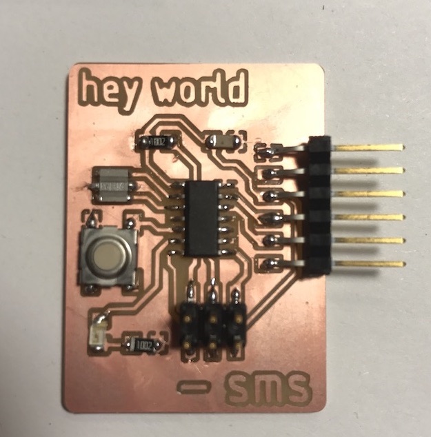
The text came out barely legible, so after fiddling with the dimensions of the text in Eagle I reprinted the board, and made a more readable version.
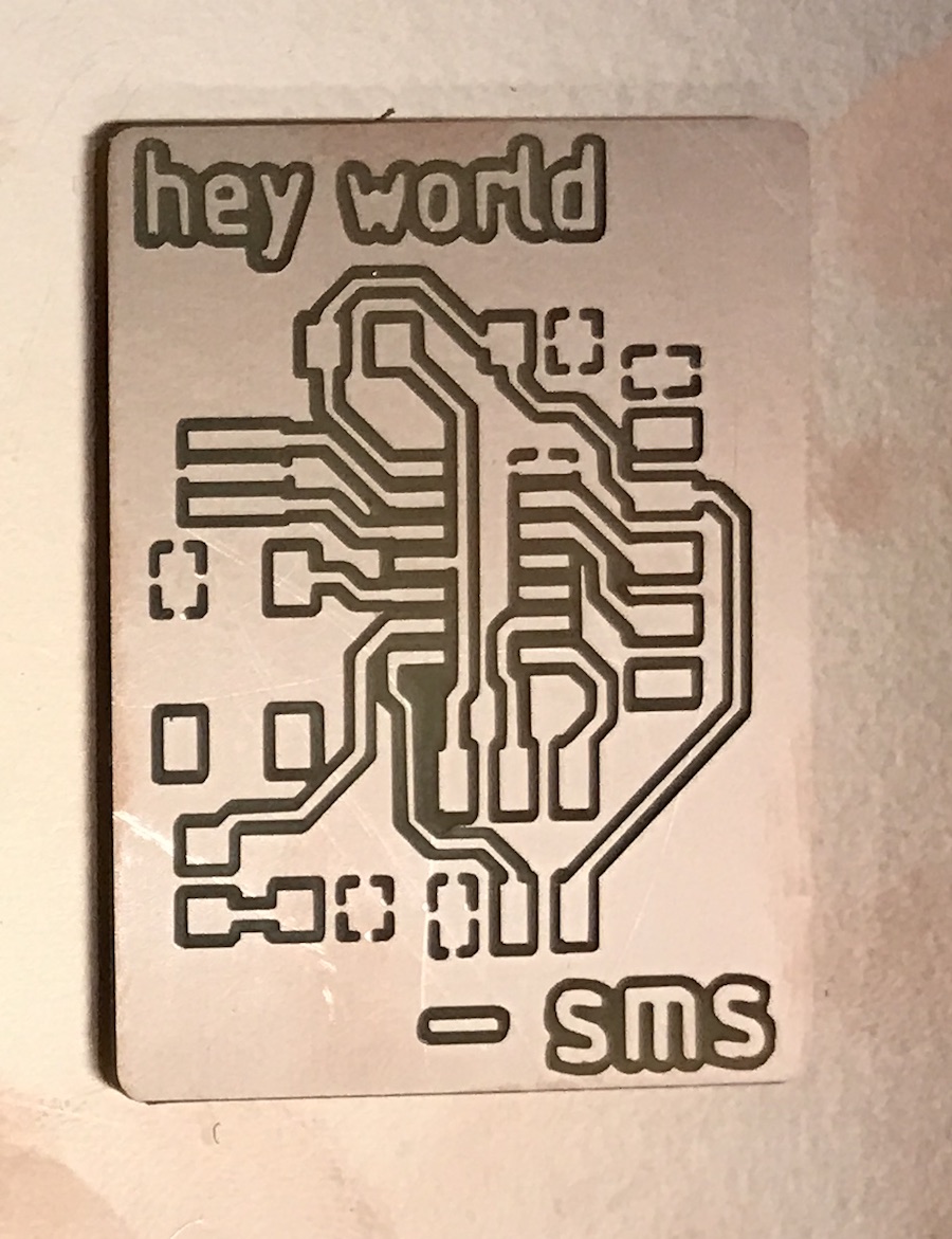
Here you can see the evolution of my board.
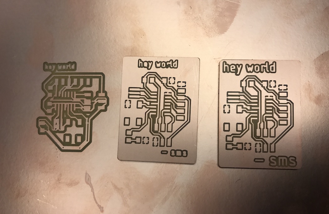
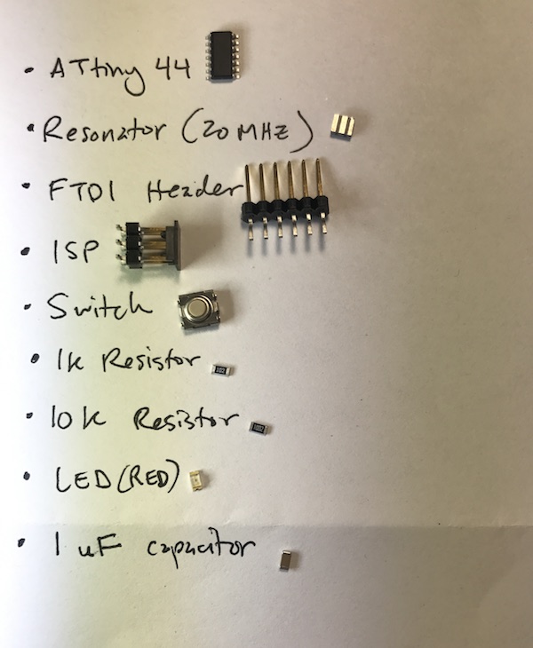
Time to stuff the board. I assemble my components, like so.
My soldering skills, which were getting decent 2 weeks ago, seem to have gone downhill since then. Nothing seems to work. My hands are shaky, probably from too much coffee. The pieces seem to be sliding around the board on a thin sheen of clear melted plastic.
Even though I haven't been applying heat for long, I'm worried that I'm melting the board. After maybe 4 hours of attempts, I'm worried I'm just damaging things and I take a break. I later find out that the clear plastic is flow (?) from the solder material, and that it is normal and good and helps with conductance. So, I haven't been melting my board. Good to know.
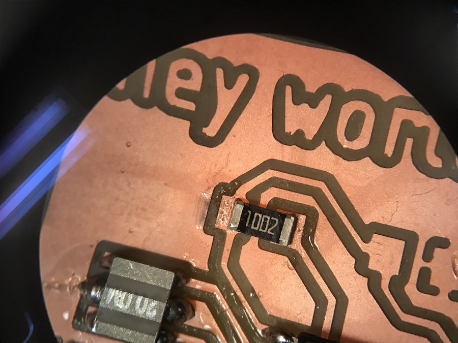
Sunday (or Monday?) I start again with the soldering. It's still very up and down. I do manage one solder that, to my untrained eyes, looks quite nice.
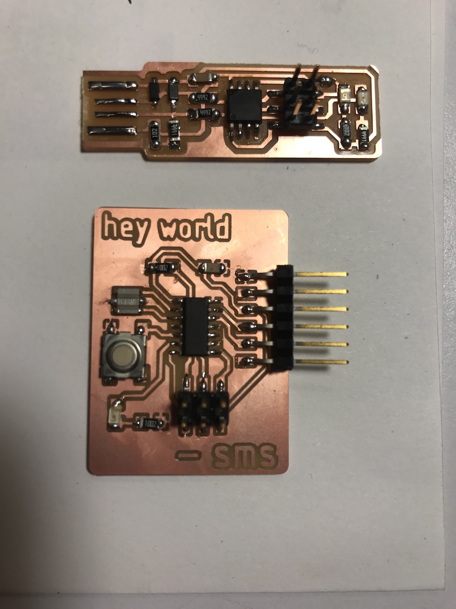
Finally done. Here is my finished board, and my board from the previous week's assignment.
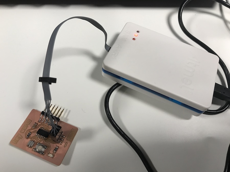
Time to program the board. This turns out to be its own frustrating saga. The instructions are aimed at Linux users, and I'm using a Mac. I start looking for a good Linux virtual machine program to install, but then I get good intel that that will actually be harder than trying this on a Mac or a Linux machine. First step is finding USB cables and a programmer. All the ones in the shop have mysteriously disappeared. Luckily, another student has his own personal set and was kind enough to lend them. Things aren't working well. Other students who are also using Macs try their computers, and a combination of cables, and nobody's setup works.
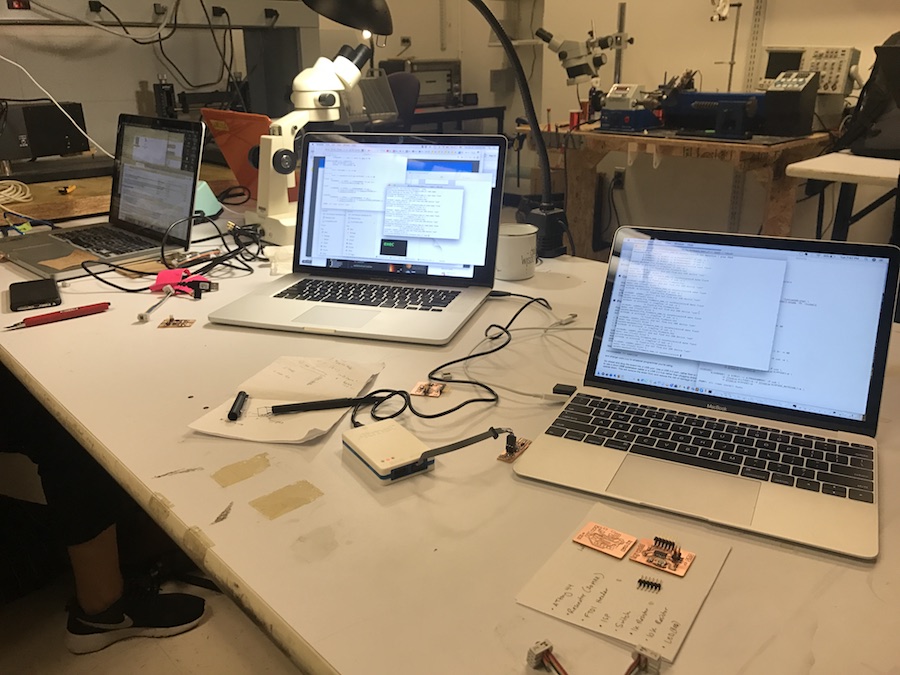
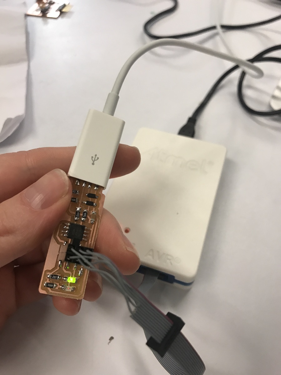
The commands don't seem to work. The programmer and computer can't recognize my boards. I'm getting a lot of "Error 1," board not found. Also I can't get my green light to turn on in my board from the previous assignment, until I switch out the USB cable. It works with a new USB cable.
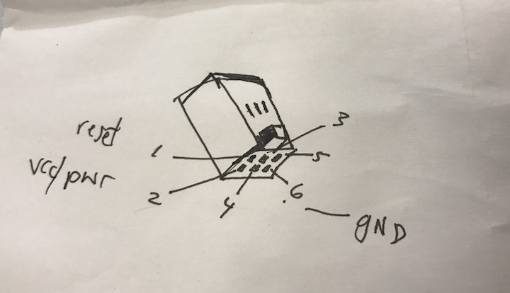
Another problem. I forgot to plug in the FTDI header. To figure out the right orientation, we need to figure out which of the 6 pins are ground and which are VCC, and line those up correctly with the ground and VCC pins on my board. Nothing on the header pins is labelled. We check the FTDI header's spec sheet online, figure it out, and draw ourselves a little diagram to help with future plug-ins.
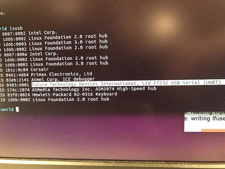
Using a borrowed Linux computer, and with the FTDI header properly attached, we follow instructions to start programming the board. We have to rename the Programmer reference in the "Make" file to refer to the specific kind of programmer we are using, a white box with a blue stripe called an Altec but in computer-speak it has another name. We get past Step 1: The computer and the board can recognize each other.
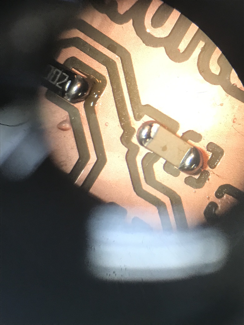
However, I can't get further and make the lights flash. Because somebody else's board worked with the same cable setup, I think the problem is with my board and not the cables this time. Looking closely at my board, I'm wondering if maybe the solders on my FTDI header aren't connecting well enough to the board. I'm going to add more solder and re-try the programming.