Week 7
Embedded Programming

Assignment:
1) Read a microcontroller data sheet
2) Program your board to do something, with as many different programming languages and programming environments as possible
Hello folks, I’m starting from a bit behind this week.
1. My chip from the last programming week (Week 5) doesn’t fully work 2. There are a lot of programming terms I still don’t understand
To address 1), I’m going to go back and add more solder to my FTDI header. Looking under the microscope, I think the solder on the FTDI header’s feet beaded up on top, so that the solder didn’t make a good connection (or any connection!) between the header and the board. Then I’ll try to program my board again. To address 2), I’m going to read some online tutorials, look at past projects, and focus on getting the basics down.
Here are some terms that have been thrown around these past weeks and I want to be sure I understand them. Maybe this will help you too…
Library of terms
Register: A register is a place that stores a small amount of data, such as a location or command, for easy accessibility by a processor.
Microcontroller: "Basically a microcontroller can be described as a computer on a chip. The difference between a microcontroller and a regular PC is that the PC is a general purpose computer while a microcontroller is a computer dedicated to one or just a few tasks.” From avr-tutorials.com
Atmel: Atmel is an American company (founded 1984) that manufactures semiconductors. They make embedded systems built around microcontrollers. This means small computers distributed in devices that need advanced functionality: think consumer electronics like speakers that communicate over Wi-Fi, flash memory devices, and of course our friend the ATTiny and its family of microcontrollers.
AVR AVR is a family of microcontrollers developed by Atmel starting in 1996.
AVRdude This is a command-line tool for communicating with the AVR family of micro controllers. It stands for “AVR Downloader/UploaDEr.” It’s used for programming the on-chip memories of the micro controllers, such as Flash memory. From nongnu.org: "AVRDUDE can be used effectively via the command line to read or write all chip memory types (eeprom, flash, fuse bits, lock bits, signature bytes) or via an interactive (terminal) mode."
Make flash This does not mean “make a light flash.” It means to write something (“make”) on the flash memory.
DDR Data direction register. Defines if there's an input or an output on a particular pin
Seral vs Parallel communication I thought the Sparkfun explanation was clear. https://learn.sparkfun.com/tutorials/serial-communication/all . All computers and components need to “talk” to each other to make the right things happen at the right time. They need to send and receive instructions. Any 2 parts can communication either by sending instructions one at a time (in serial fashion….one comes after the other), or in parallel fashion (a bunch of instructions at the same time).
Re-programming the USBTiny (ATTiny45)
First, I installed CrossPack, and Homebrew (via brew.sh)
I plugged in my USBTiny board (aka the FabTinyISP board) via the ISP header and the USB cable, which needed an adapter because I have a new Macbook that frustratingly only has ONE port, a USB-c (thanks, Apple)
I had done the initial programming setup for my USBTiny board in Week 5, but because I did it on a borrowed Windows computer and an Atmel controller, I wanted to make it work on my own computer, with whatever controller was at hand. The only one in the shop was the AVRISP2.
I downloaded the firmware source code using the link given on the class website, and extracted the zip files. Then, using Terminal, I located the directory using the “cd” command and ran the “Make” file. This creates the “fts_firmware.hex” file that will get programmed onto the ATTiny45 micro controller that is on my chip. I opened up the “make” file and edited it so that it knows what kind of programmer I’m going to use to program my board, and thus will be able to communicate properly with that programmer. Since I’m using the AVRISP2, I find this line in the makefile and edit it from : "PROGRAMMER ?= usbtiny” to PROGRAMMER ?= avrips2" Next, I used the “make flash” command to install the hex file on my board’s flash memory. Things seemed to work ok.
Programming the Hello World board (ATTiny44)
Before I tried to program my “Hello World SMS" board, Brian pointed out that some of my solder joints might cause problems. I had been trying to make small, petite solder joints but it turns out that can cause problems. Your solder needs to flow on to the copper enough to connect the component with a good amount of surface area. In short, your solder joint shouldn’t look like a ball or a bead.
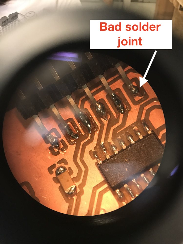
These solder joints were improved.
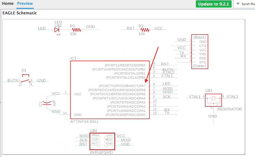
I wrote a simple program to make the LED light blink on and off. I cloned the Echo program and removed the Echo commands to make a simpler workspace. I named this new file blink.c. In the program, I added some definitions to tell the board which Pin my LED was on, and that it should read that pin as an output. We need to tell the microcontroller and the program which pin it should read/write as the "light." Basically, which pin is connectd to the LED? Referring to my Eagle schematic that I drew when designing my board, we can see that the LED is connected to PA7.
The lines added here are the newly defined terms in lines 13-15, the commands in line 31-32, and the the program itself in lines 34-38.
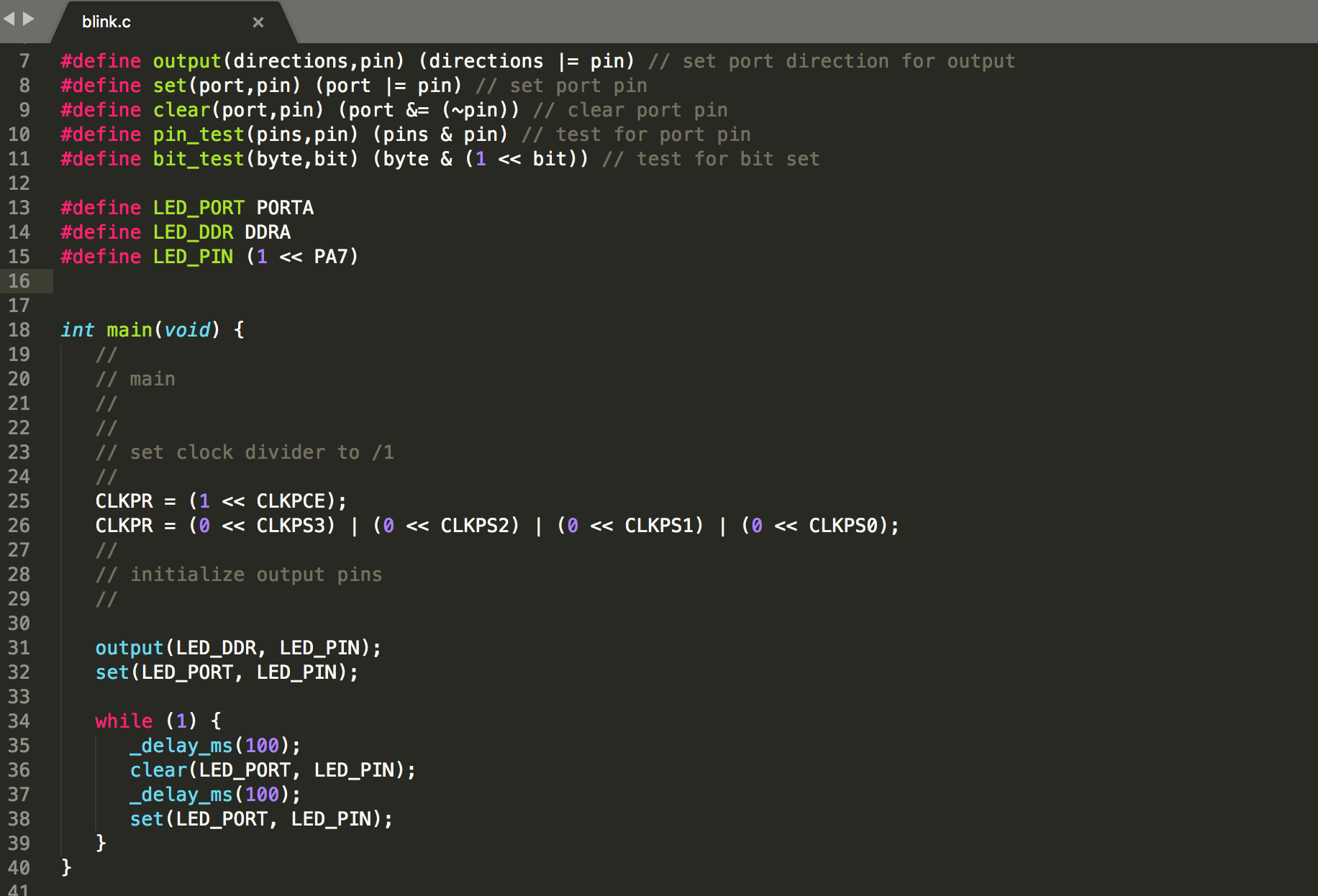
On line 15, I defined that the LED is attached Pin PA7, PA meaning "Port A."
My program, on lines 34-38, will loop forever as long as the board has power. It starts by telling the board to turn the LED light on. Then to wait 100ms, then turn the light off. Then repeat.
To keep my files orderly, I make a new folder on my desktop called "blink" and put my blink.c program in there, as well as the blink.c.hex file and the makefile.
The first time I ran my blink program, I got an Error1 message.
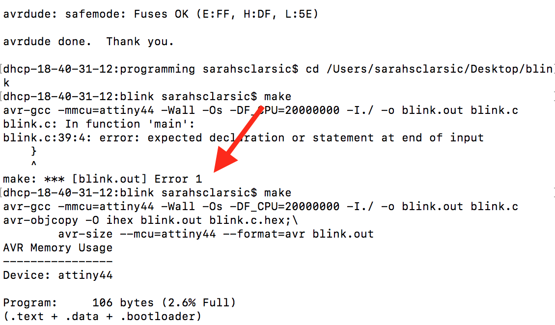
The error description told me that I didn't close the brackets at the end of my program. I went back and edited my blink program file to close the brackets, re-ran the program, and it worked! My LED is blinking on and off. The light is dim though, which Brian thinks might be because I used a resistaor that is too large.