project daredevil
Background
Over the summer, Matthew Shifrin, Dan Levine and I aimed to work on a project in which we’d make entertainment media accessible to the blind via technology. A lot of present media is not able to be experienced richly in nonvisual ways. Comic books, especially superhero comic books, are a pop-culture mainstay in America and beyond. However, their visual non-interactive nature makes them inaccessible to people who are blind.
From Matthew, I learned that some comic book illustrators create their drawings based on scripts. We aim to transform comic book stories into a sensory experience that is nonvisual.
What if you could experience what the main character of a superhero comic book was experiencing during an action scene? We aim to induce sensations such as flying, falling, driving a spaceship and more.
The story in our initial prototype involves the following actions.
- flipping from tree-branch to tree-branch,
- landing on the ground
- kicking someone in the face
- pulling on someone’s arm while the other person pulls just as strongly i.e tug-of-war)
- and getting sucked into a vortex.
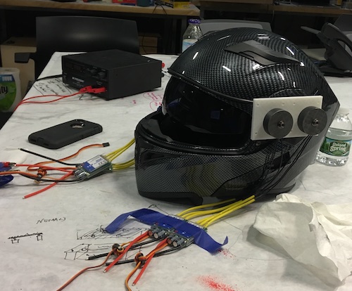
To make progress toward this goal, I am putting together a helmet that will induce the sensations of the following actions through forces on the helmet. Specifically, we hope to create and execute acceleration profiles on the head that will approximate the acceleration profiles of the actions described above.
Market
I am creating something that could contribute to augmented and virtual reality experiences (moving beyond visual and further exploring tactile).
Design Considerations
- forces induced on head should not cause damage/whiplash – certain time and force threshold
- main health risks: whiplash and nausea
- one possible solution: double layer helmet - one outer layer helmet would be affixed to your shoulders and provide an additional boundary
- reducing amplitude of acceleration but still making sure the “pattern of acceleration” is perceivable.
- trying to make sure ppl can recognize force patterns being applied via the helmet to simulate a first person experiencee
Related Work
M-Blocks: self-assembling robots that achieve pivoting movements by quickly transferring angular momentum accumulated in a self-contained flywheel to the body of the robot.
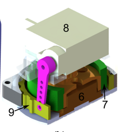
Figure 2b “It is composed of a brushless DC motor (6) which spins a flywheel (7). A servo motor (8) is used to tighten a belt (9) which rapidly decelerates the flywheel to create an impulse of torque.” connector
Cubeli: “a 15×15×15 cm cube that can jump up and balance on a corner.It accomplishes movements via momentum wheels mounted on three faces of the cube that rotate at high angular velocities and then brake suddenly, causing the Cubli to jump up. Cubli also has controlled motor torques are applied to make it balance on its corner”
The field of motion simulation and haptics also have related work i have not investigated.
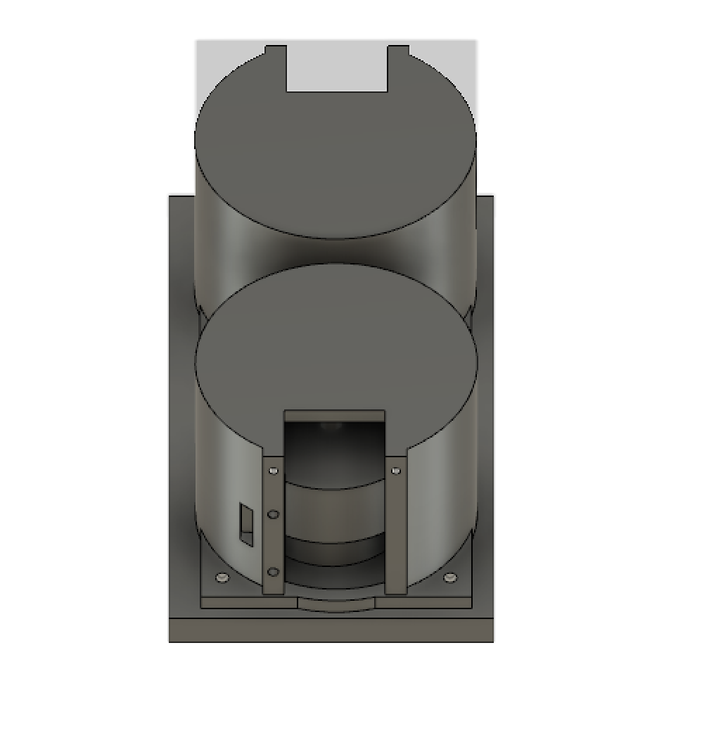
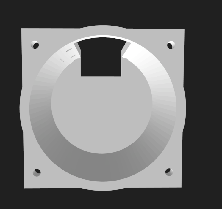
Mechanical Design
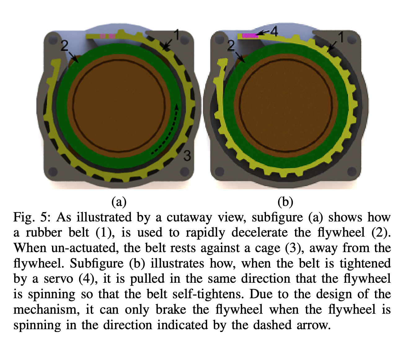
The mechanical design utilizes conservation of angular momentum to generate an impulse on the wearer of the helmet’s head. The setup is similar to that mentioned in the M-blocks paper. I have a spinning reaction wheel (flywheel) driven by a DC motor. The flywheel gets quickly stopped via a belt mechanism that is controlled by a stepper motor.
Applying this mechanism to the helmet, I needed to figure out how many motors are necessary and how to actuate them to model the target acceleration curves characteristics of the actions I aimed to simulate. The most basic movements to tackle:
- turn head left
- turn head right
- move head up
- move head down
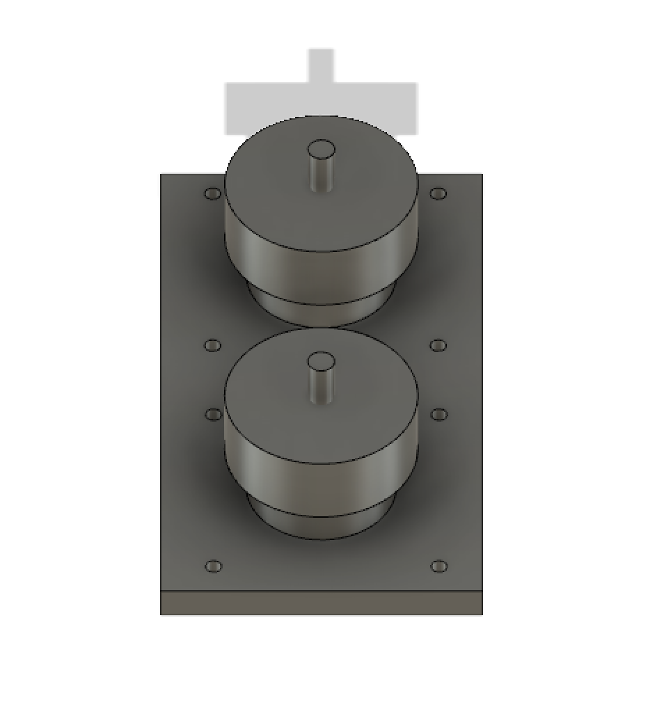
This can be done with two motors on each side of the head. However, to create acceleration curves, we may need more motors (that will be saved for a future exploration.)


Electronics Design
- 1:1:1 ratio of esc to motor to pwm pin.
- single microcontroller outputting a pwm signal in n pins where n is the number of escs
- powering the board and motors, we will use a battery pack. we do not want to mount this directly on the helmet for safety reasons, so we will keep the battery pack on the side.
Interface Design
MBED
Making my own microcontroller, it has been recommended to me that I make my processor compatible if possible. Mbed is a platform and operating system for internet-connected devices based on 32-bit ARM Cortex-M microcontrollers (wikipedia).
related links to learning about how to make a custom mbed board: 1. target definition for custom board 2. prototype to hardware
I’m exploring which microcontroller to use–ATTiny44 or ATXMega or ATMega.
3. How to design a microcontroller circuit (w/ a focus on ARM cortex-M devices)
Mallory design review:
Torque = change in angular momentum about some center + (radius from joint to center of rotation)cross product with dP/dt linear momentum = P = m*angular_velocity cross r_qc (where q is center of spinning and c is some other point a distance r away from q). c = center of mass
Torque is gonna be directly related to the change over time of (inertia matrix times the angular velocity)
arduino from scratch using atmega16u2
Materials
- motorcycle helmet
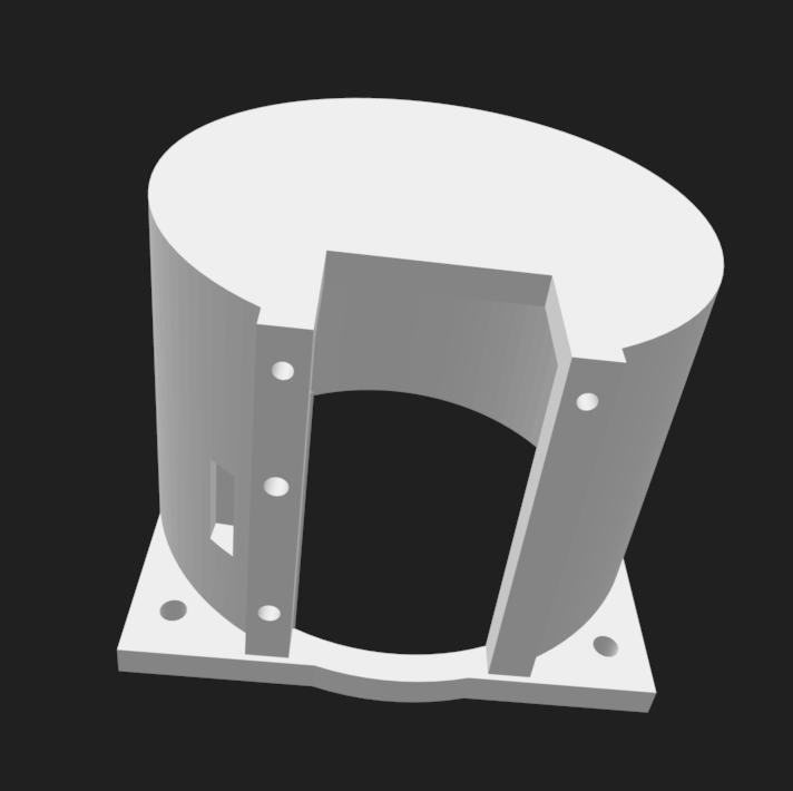
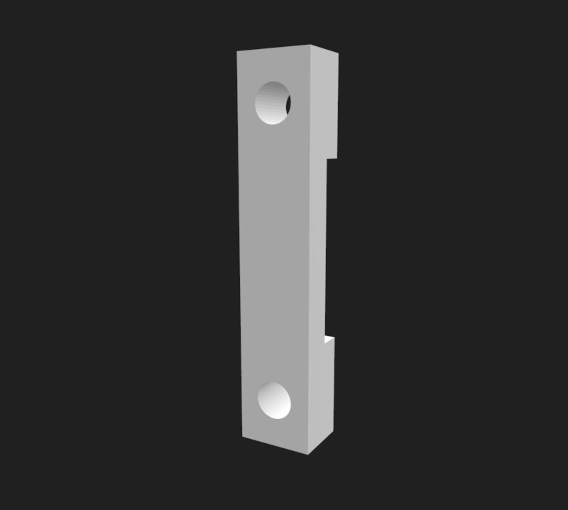
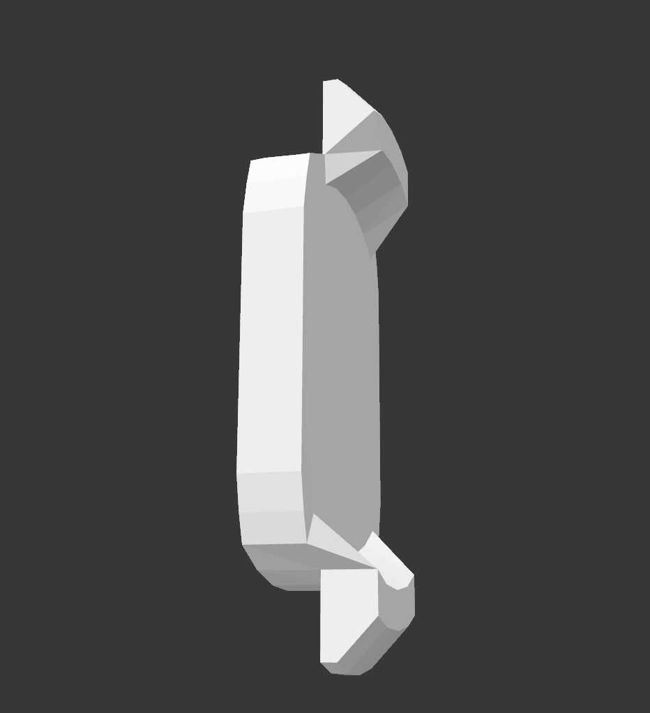
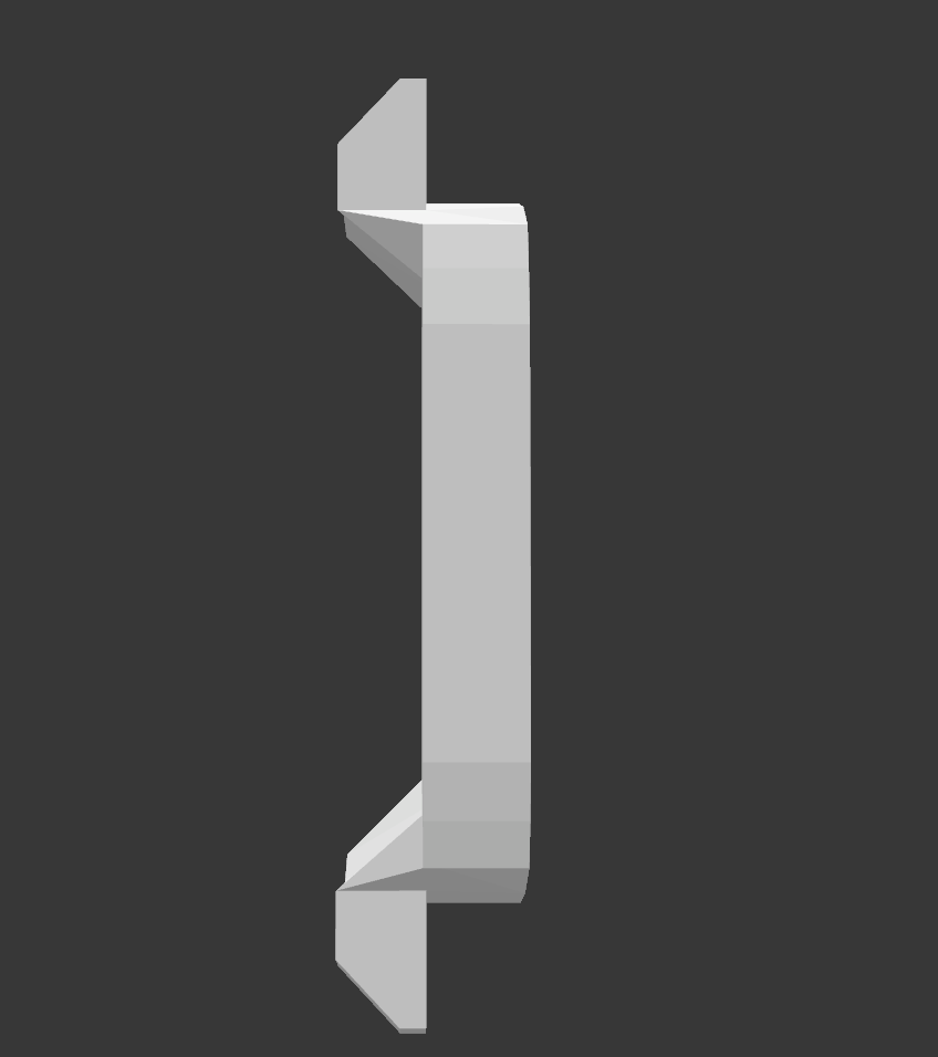
- 3d printed brackets
- 2 bldc motors
- 2 ESCs
- 2 servo motors
deciding between motors
comparing servo to stepper motors for the purpose of comparing my different stopper mechanisms, i found this info helpful
comparing different servo motors analog versus digital tells me that digital is more reliable and can accelerate more quickly with more torque.
In picking a servo motor–more torque versus lighter weight.
HobbyKing™ HKSCM9-5 Single Chip Digital Servo 1.4kg / 0.09sec / 10g HK-5320 Ultra-Micro Digital Servo 0.075kg / 0.05sec / 1.7g
servo motor dimension diagram () from fab lab inventory,
12/2/18 At this point, we’ve got code running on the lychee mbed microcontroller board. We’ve been able to use pwm signals to get the servo motor working but we need to get the bldc motor to work w/ the esc!
12/4/18
- fixed motor mount
- tried and failed to make an accelerometer pcb
12/5/18
- assembling
- interface design and implementation
- [] creating a pheonix client w/ node that will communicate with the pheonix server made by dan following documentation.
- following this tutorial for hosting the webpage w/ node; uses this sample code
- following this tutorial for learning pheonix channels API tonight
- In my system, i am developing a pheonix client to subscribe to a channel hosted by a server. The pheonix client might need to open up the channel?
- networking architecture is such that the browser client will send a message to a particular channel (publish to it) and the microcontrollers will be subscribed to that channel. “Once the connection is established, each incoming message from a client is routed, based on its topic, to the correct channel server. If the channel server asks to broadcast a message, that message is sent to the local PubSub, which sends it out to any clients connected to the same server and subscribed to that topic.”
so basically, i need to declare a socket (and corresponding socket handler)
Why use Phoenix? because its a web framework that’s useful for creating real time communication between devices via channels. “Phoenix Channels can support millions of subscribers with reasonable latency on a single box, passing hundreds of thousands of messages per second. And that capacity can be multiplied by adding more nodes to the cluster” (pheonix channel docs). The tradeoff as that there are dependencies and a learning curve for getting something working in Phoenix. Read more about Pheonix here.
As I install dependencies, I’m also finding that Pheonix is quite heavy, with some large dependencies including Elixir (the language that Pheonix is written in) and Erlang (the language Elixer compiles to).
Given how heavy Elixir is (boilerplate code and opinionated structure), how might we only take the part of the Pheonix (the channels) that we want?
12/10/18 Coming back to project… rethinking system integration and project management. I still have a lot to do with testing parts of the system and iterating.
Today, I need to
- make and program accelerometer pcb
- 11:30-1:30 schematic and layout took
- 4:30 setup the machine + job using mods
- 4:41-4:53, 5pm run trace (2 times) (130,10), (130,49)
- 5:15-5:23 cut outlines
- 5:30-6:00 practice accelerometer
- 6:04 stuff the rest; ran into trouble actually soldering the accelerometer, incrementally soldered and tested programming my board
- MIDNIGHT :( programming successful even w/ accelerometer soldered on, but not receiving anything from the board over serial (using Neil’s program to visualize the acceleration data).
- 30 minutes debugging, got advice to connect to the component via wires, stopped because it was sketchy.
- modify design and 3D print the servo motor mounts to connect to the helmet
12/11/18
- [] finish accelerometer board + connect to interface
- met with zijun who helped me by showing me how he solders the axl and also showed me how to use the oscilloscope to check the board. it looks like the board i had was unable to communicate over serial for some reason.
- milling two more boards…gonna stuff one
- was able to program
- unable to read from serial
- without accelerometer soldered, used oscilloscope to measure voltages and found a trace that wasnt cut that was shorting pins on the attiny45. to do this i was using a simple blink program i wrote by modifying neil’s code (blink.c, blink.make). + testing was funny because I added in a delay in order to create my own square wave. I was worried when I saw that the line was still high and not toggling, but later learned that this was because the delay of counting to 1 million was way to high. PLUS the attiny45 is an 8 bit microcontroller so it can’t coun’t that high anyway?
- fixed that w/ an xacto knife to cut the traces, got signals i wanted!
- then i soldered the accelerometer and was recieving no messages from serial.
- DEBUGGING TO BE CONTINUED
12/12/18
- acquire more servo motors
- finish interface for creating and connecting to the helmet via the internet
- create the appropriate UI for sending messages to the server (based on my original)
- SHOULD THIS BE SIMPLER than i thought?
- test connection socket
- follow up about machining
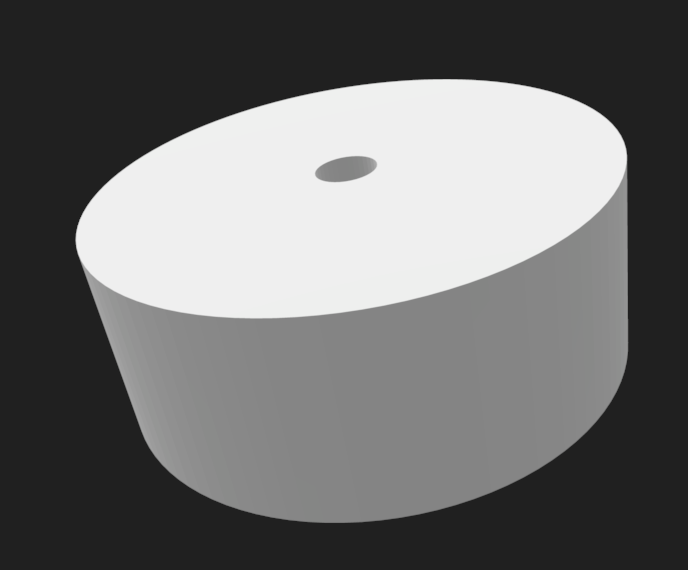
- ordered new rod + endmill to machine flywheels
12/13/18
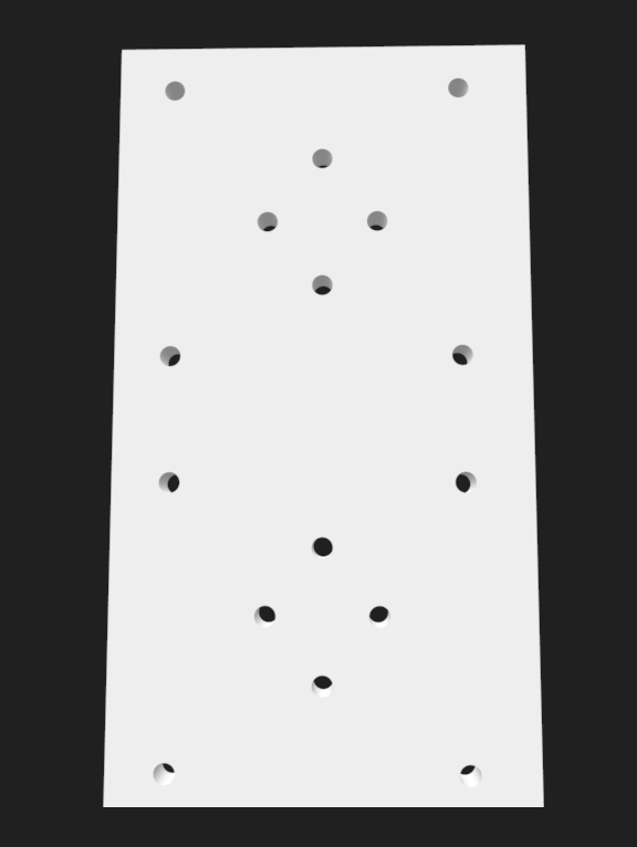
- define process for machining flywheels + create a test piece
- TODO: insert documetnation for the machining of the flywheels
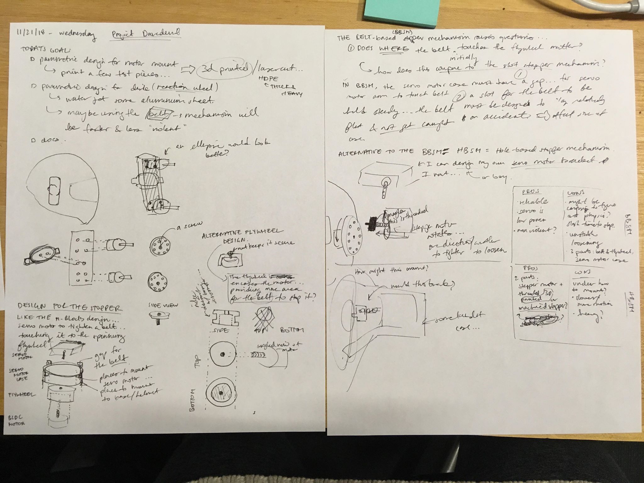
While implementing the web interface for controlling the helmet, I realized that the belt mechanism for stopping only allows for the spinning to occur in a single direction. Should rethink the mechanics of how this works.
Idea: waterjet teeth into the sides of the flywheel so that we can use the stopping mechanism demonstrated by Cubli. We have a servo motor move an arm that will not take the blow of the impact because there will be a piece on the servomotor mount for the arm to press against.
If we are to do this, we will need to make an attachment to the servo arm using pieces of sheetmetal.
- [] is it worth doing a new mechanism? how can we rework the original?
12/14/18 carrying actionables over…
- finish machining flywheels
- test flywheels on motors, more violent/intense than expected
12/16/18
- debug serial communication for the accelerometer
- plan:
- rx.py
- use oscilloscope on the rx pin
- check connections to accelerometer (try soldering again)
- plan:
Success:
- finish interface for visualizing acceleration data
12/17/18 It’s the day before demo day! Triage to figure out what’s realistic to accomplish by tomorrow:
- finalize web interface
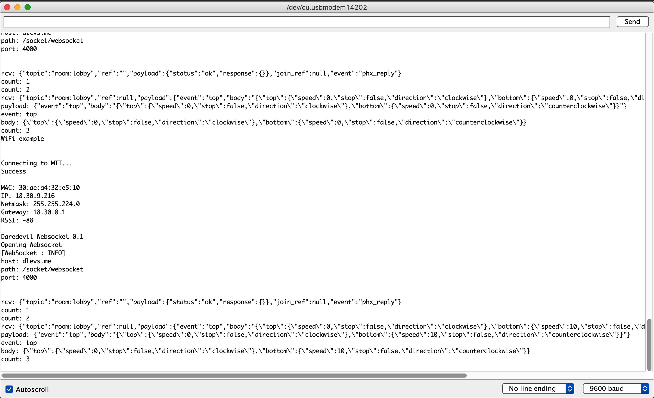
- verify connection of web interface to pheonix server
- realized that web sockets wouldn’t work when connected via MIT Guest, but worked when connected to Media Lab.
- verify connection of mbed lychee to pheonix server
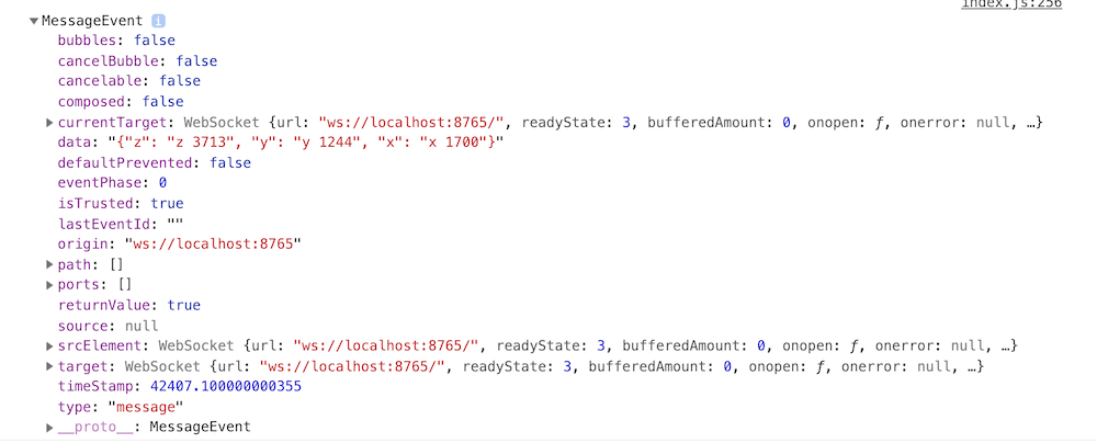
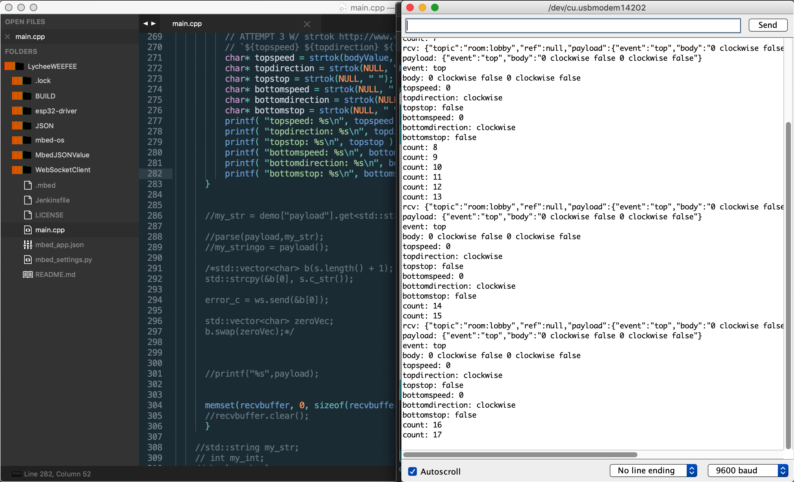
- c code to parse messages from the web interface
- mbed json library
- char * versus strings
- mbed only uses c++ 98
- getting setup w/ mbed-cli
-
key thing was to download the right ARM compiler
-
Invoking GCC * On Linux and Mac OS X, either invoke with the complete path like this: $ $install_dir/gcc-arm-none-eabi-*/bin/arm-none-eabi-gcc
Or set path like this: $ export PATH=$PATH:$install_dir/gcc-arm-none-eabi-*/bin $ arm-none-eabi-gcc
-
- building on Dan’s code lycheeWEEFEE
- more string shenanigans parsing message in networking
- https://stackoverflow.com/questions/5188140/c-const-char-to-stringstream
- my woes were caused by passing by value instead of by reference
- single quotes denote char literals, while double quotes denote string literals
- mbed json library

- [] c code to control motor consistently with desired speed
-
https://www.pololu.com/blog/17/servo-control-interface-in-detail duty cycle spec for RC receivers
20 ms pulse width -> 50Hz pwm (default output from Arduino)
3V signal versus 5V signal…
- comparing to Arduino, which is 5V… we probably want that
-
ESC still causing trouble; checking out the datasheet to learn more about the beep codes
- the ESC has a set of possible modes, one of which gets selected during the programmatic mode
- [] up and down motion (flexion + extension) with just one motor on each side both accelerating and then decelerating
-
- [] wire management
-
[] system integration (demo preparation)
- part inventory
- [] learn about how to understand the acceleration data?