echo hello
“redraw the echo hello-world board”
Using Autodesk Eagle (free for non-commercial use), there are two main steps: 1) create a schematic consisting of symbolic representations of the parts connected by wires, forming your circuit. 2) layout your schematic denoting to-scale where your parts will go and what traces will exist to connect the parts.
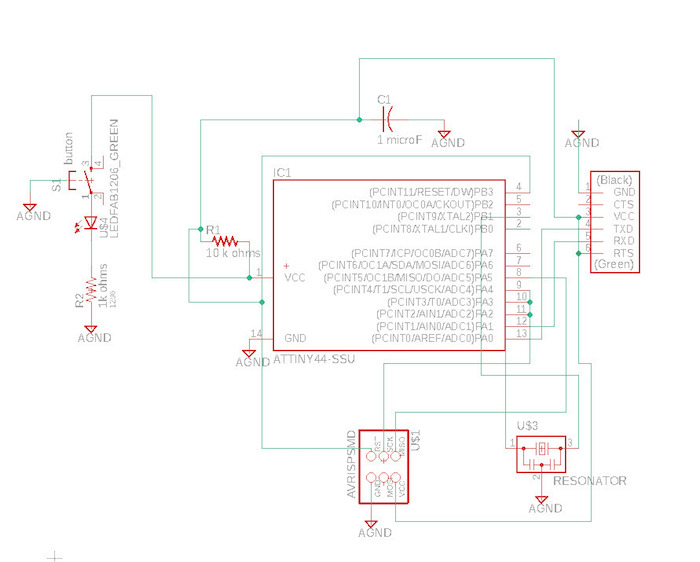
create the schematic
I did this by referencing the echo hello-world board trace provided by the class.
Tools:
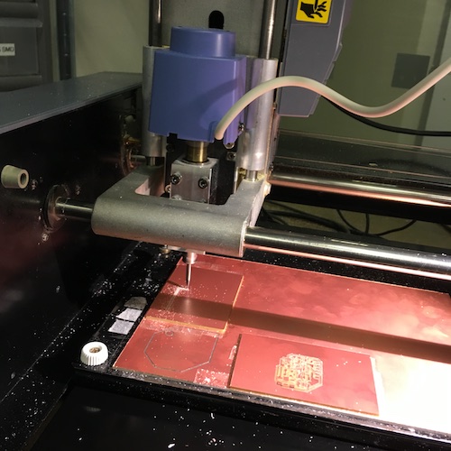
- Roland MDX-20 Mill
- Double-sided tape
- Sacrificial board
- Isopropanol (for cleaning off our oils that oxidize the copper)
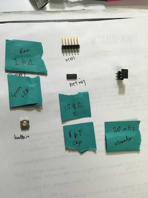
Materials:
- 1x Milled board
- 1x ATtiny44
- 1x 1kΩ resistors
- 1x 10kΩ resistors
- 1x 20 mHz resonator
- 1x 1 uF capacitor
- 1x green LED
- 1x 2x3 pin header
- 1x FTDI
finding your parts
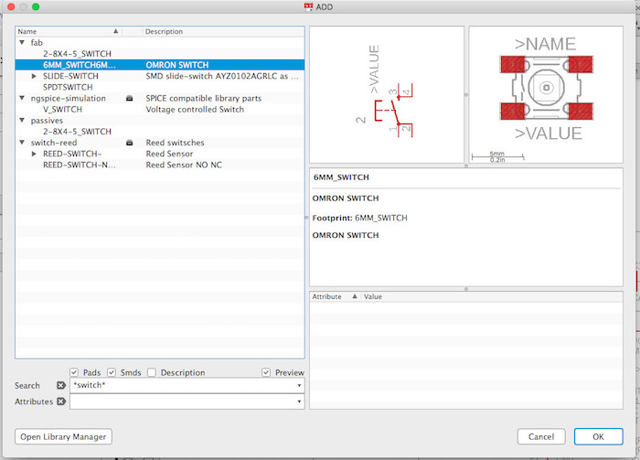
Every part you want to add to your circuit must be in a library in Eagle. Luckily, HTMAA provides its students with a library containing all the parts provided by the fab lab here at the Media Lab. But if you want to add information about a part that isn’t already in Eagle, one easy way I found is to use Ultra Librarian–just input the part number, and download whatever CAD file you need. For Eagle, this is an SCR file that represents a library containing the part you want. I did this when I couldn’t find the specific resistor I was looking for.
connecting your parts Once you’ve laid down all your parts, the schematic consists of symbolic representations have labels for the different pins and part types. Using these labels, you can determine and make connections (using the “Net” tool) between the appropriate pins. Here’s where the trace becomes extra useful.
For my assignment, I also needed to add (at least) a button and LED (with current-limiting resistor). Neil said that typical current-limiting resistors are 1k Ohms, but I wanted to figure out the right size resistor to use with the LED from the specs on DigiKey. I learned that the ATTiny44 uses a VCC of ~1.8 V to ~5.5 V, so assuming max voltage, 5.5 V and taking into account that the LED can handle up to 10 mA, 5.5 V / 10.mA = 550 Ohms = the minimum resistance I should use. I went for the 1k Ohm resistor.
Adding the button. Based on the datasheet, I see that the button has a resistive load of 1 to 50 mA, 3 to 24 VDC. This tells me that it’ll be fine to provide a 5.5V input to the switch.
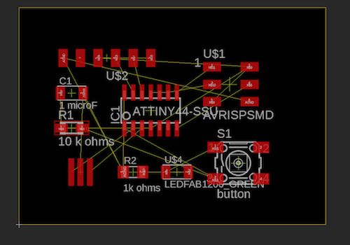
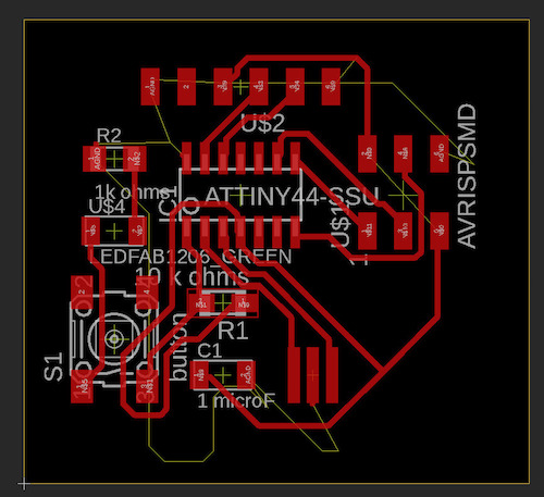
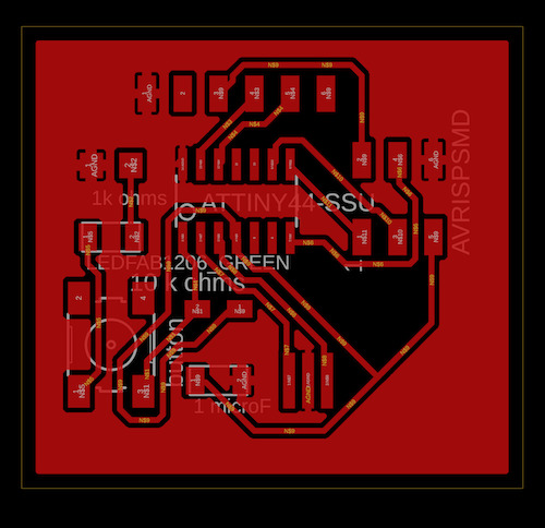
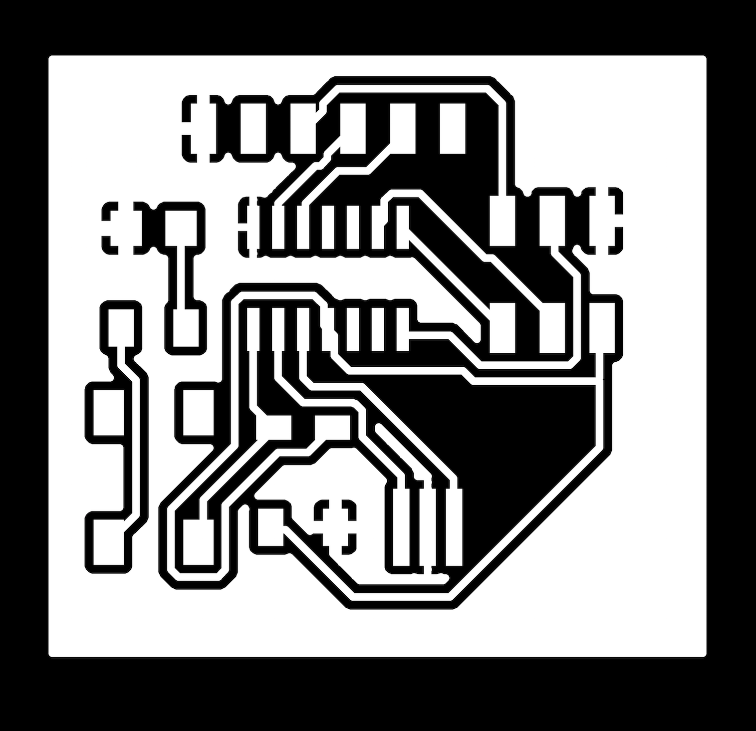
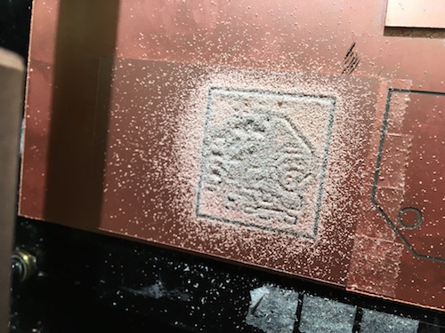
create board layout from schematic First, I moved the parts to about the place I wanted them to be. Then I started adding the design constraints (Tools > DRC). I set all clearances initially set all clearances to be 15 mil, but that is smaller that 15.5 mil (the size of the endmill we are using) which won’t work. I didn’t realize this mistake until after I had attempted to draw my own traces, failed, and then autorouted and created a rats nest.
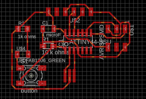
Because I had already routed and also created a rats nest, updating the design constraints resulted in many Clearance errors. The new constraints: DRC > Clearance is set to 17 mil (so that the space is large enough for the mill to actually go and remove the copper). I set DRC > Mask > Thermal Isolation to 18 mil based on Tomas’s advice to make enough room for the mill to cut where the GND pads connect to the rest of the board.
To resolve these errors, I ripup’ed the ratsnest (polygon) and then redid some of the traces by ripping them up and rerouting. Initially, I was able to just move the trace instead of having to redraw it. But then I ran into trouble–I didn’t have enough fine control to move the trace just a tiny bit before overlapping with another part. To address this, I used the “grid” command to open up controls and set the alt grid to be 2. This grid is what the trace snaps to as you are drawing.
Then it was time to do the rats nest! I ran into some trouble with that only because I named the signal of the rat’s nest GND even though AGND is how I was referring to ground. Once I corrected that, the rats nest was a success!

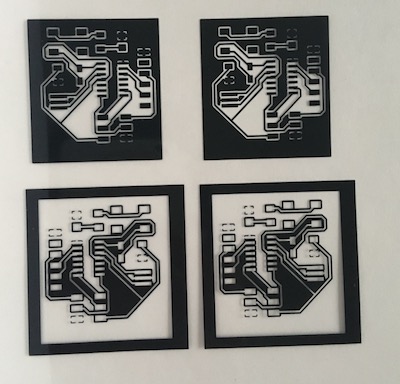
“make it”
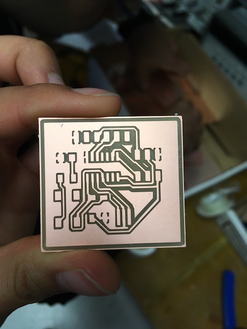
I wasn’t in town for 5 of the 7 days I had to work on this, so when I was in California, my boyfriend Yanni and I wanted to try to fabricate the board by etching.
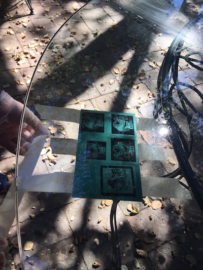
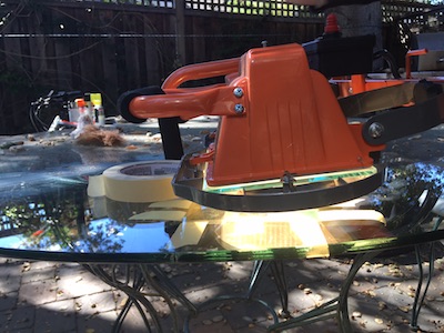
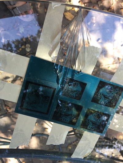
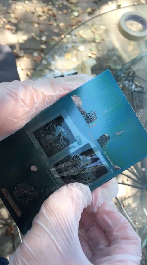
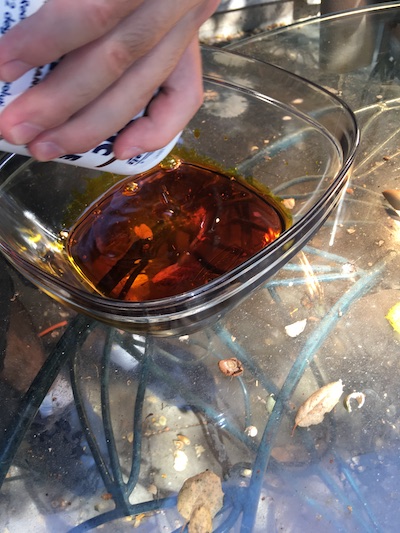
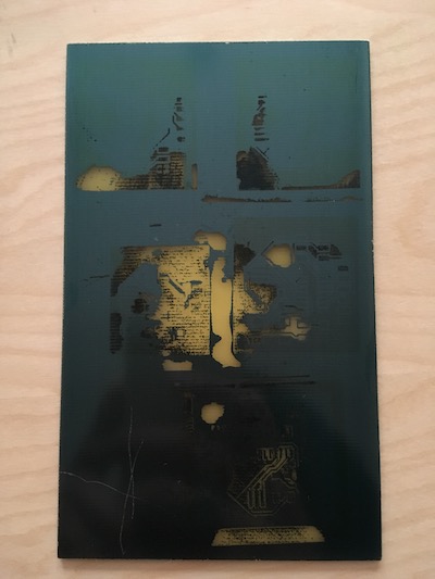
This process involves a special board that has a light sensitive coating. Parts that are exposed to the light will not be removed by the chemical used to etch the board. With this in mind, Yanni and I did the following:


“test it”
To test, I went straight to programming my board using the Atmel AVR ice. The orange blinking light signaled to me that I either had a problem with my reset pin or the I had plugged the connected in the reverse orientation. Reversing didn’t help the situation and the light changed to be a red blinking light, indicating a short circuit. I didn’t get farther than this–I’m going to need to debug my board and potentially remake.
…
Okay! With help from Kreg (a previous TA), I learned how to use a voltmeter in order to debug my board. There are two settings we found useful:
- test continuity: if the two ends are connected or the same, the voltmeter will beep. Note that the voltmeter’s black end should be touching ground. TODO: image
- measure voltage: measure the voltage difference between two points. TODO: image
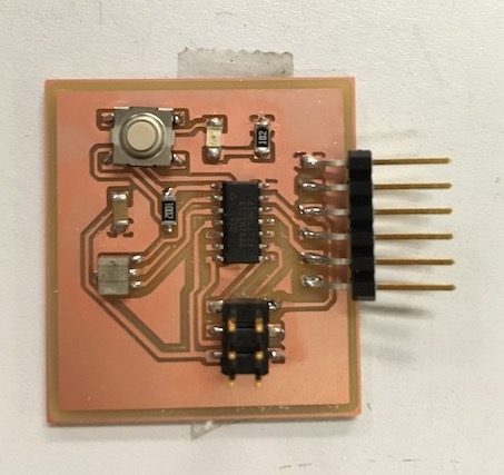
Through this debugging, I learned that the processor did not have a proper power source because its vcc wasn’t connected to anything so I added a jumper wire to connected the VCC from the FTDI header to the VCC input of the ATTiny44. TODO: image It was pretty difficult to do this, and probably bad practice–I recommend creating a new board instead.
After adding the jumper wire, I was able to successfully program my board to echo characters sent over to it via serial… but not without troubleshooting issues specific to programming microcontrollers with the Atmel AVR ice on Mac.
troubleshooting programming on mac The first problem I ran into was the following error when attempting to program my board
avrdude: usbdev_open(): error claiming interface 0: Permission denied
avrdude: usbdev_open(): no usable interface found
avrdude: jtag3_open_common(): Did not find any device matching VID 0x03eb and PID list: 0x2141
avrdude done.  Thank you.
make: *** [install] Error 1
With Sean and Kreg’s help, I followed the approaches given by a Medium post by David Ramsay: AVRDude and Atmel ICE on OSX 10.3 High Sierra. After doing this, I needed to unplug and replug my programmer and board before the changes kicked in and I was able to successfully program the board.
I tested that the program was functioning correcty using the Arduino IDE. You can go to Tools > Port and select the port that corresponds to the usb hub connected to your pcb. Then, you can go to the Serial Monitor, ensure that the baud rate is correct, and type to your board :)