music shrine
“make something big”
idea
Initially, I wanted to make a loft for my friend Josh. But I realized that the project wasn’t really fit for taking advantage of the ShopBot we were using, so I asked him what else he would appreciate for improving his room. The most exciting idea was the idea of making a piece of furniture that would highlight music as important to him–a kind of “music shrine”.
Josh plays both electric bass guitar and trumpet, but I actually didn’t know he played trumpet until recently. I have only ever seen him play guitar. He’s more inclined to play bass because his guitars are easy to access. But if his trumpet & accessories for it were as convenient, he’d probably play it more.
Josh also has records, music books, and is planning to get a turn table for playing records.
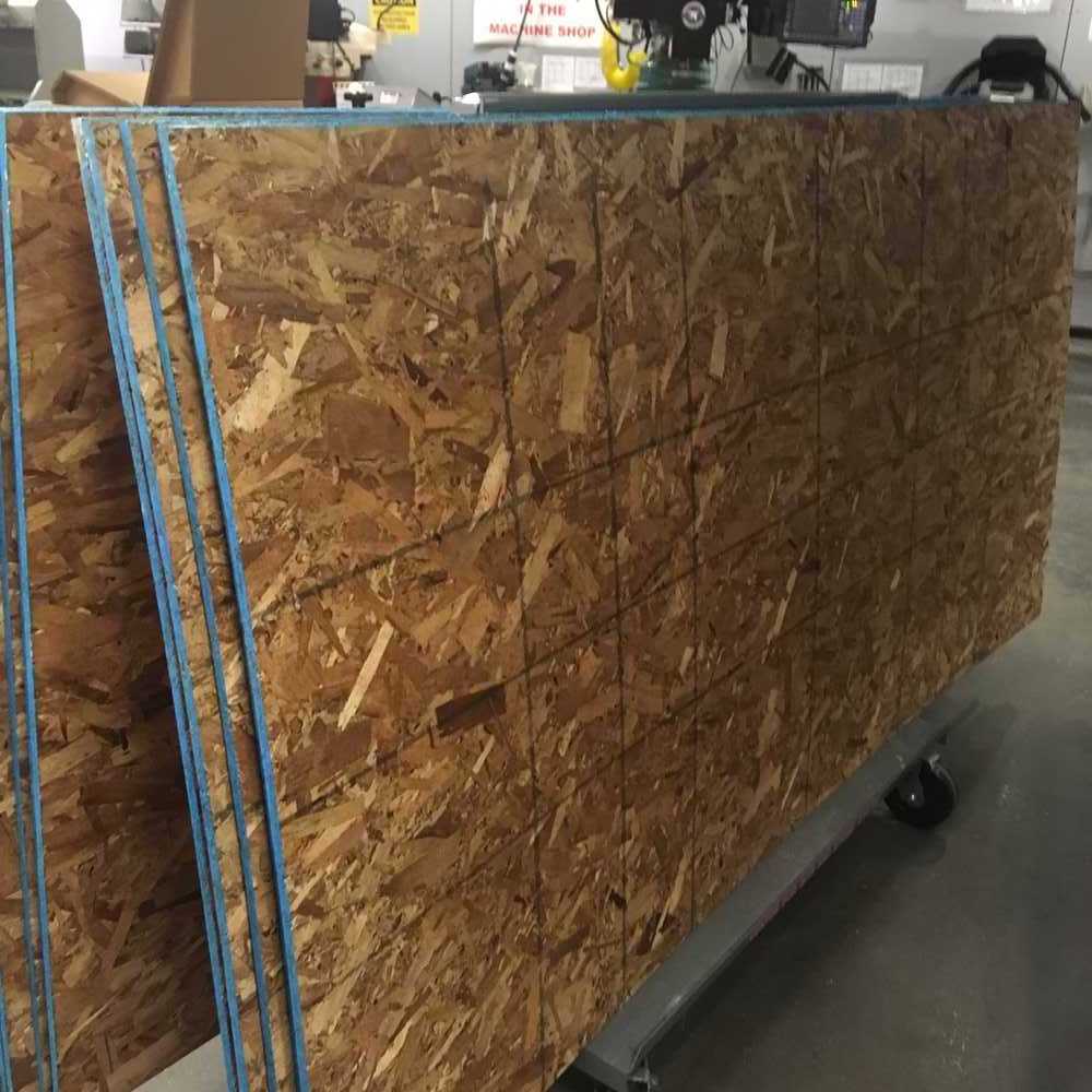
He also has a pretty big part of his room that he could dedicate to music. Space we got excited about filling before realizing our material size: 4’ x 8’ sheet of OSB (Oriented Strand Board)
My initial design, filling the 29” by 53” by 37” volume in Josh’s room, involved extra table space and another bin more holding more records. I scaled down the design to support the essentials:
- record player (turntable)
- records
- music books
- trumpet
- trumpet mutes

process
Software Tools
- Autodesk Fusion 360 for CAD
- CorelDRAW for laying out vectors
- VCarvePro for laying out vectors + post processing (adding tabs + dogbones/tbones)
- ShopBot3 for interfacing with machine and actually running the job.
Hardware Tools:
- Full Size ShopBot
- Power drill
- ~10 Screws + drillbit corresponding to screw thread size
- 1/4” downcut endmill
Materials:
- 4’ x 8’ sheet of OSB
Design:
Based on our ideas, we sketched out some possiblities.


In Autodesk Fusion 360, I used the following workflow for prototyping and designing.


As I added different components, I would use the faces of existing bodies to define the planes, since I wanted parts to be touching each other as the parts were being assembled.
I didn’t have in mind that all the faces that were in the same plane could be cut as a single piece until I had a solid vision/model for how the pieces would end up fitting together. Once the pieces were all together, I selected the appropriate bodies to ‘combine’.
Before exporting .dxf files for each of the faces I wanted to cut, I wanted to make sure the pieces would fit together in real life. At this point, the design (and sketches) were complex enough that I couldn’t actually visually verify that there weren’t interferences… luckily, Autodesk fusion has a tool for that!

To resolve the interferences, I went through and used Autodesk’s highlighting to determine which pairs of bodies were contributing to what interferences. From there, I investigated the interference to come up w/ a plan.
- remove bodies that I don’t want nor care about Then, for each interference…
- pick one of the two bodies that needs to be cut away
- create a sketch on the face of the body i want to keep
- extrude that sketch as a cut into the body to cut away; this actually cuts away the body you wanted to keep SO!
- extrude using the same sketch, this time creating a new body.
To obtain the dxfs, I right clicked on each body and created a sketch from that body. This made clean sketches that didn’t include the construction lines I had used.
DXF Files:
individual parts
- back.dxf
- book_shelf.dxf
- far_right.dxf
- mutes_shelf.dxf
- record_bottom.dxf
- record_front.dxf
- shelf_left.dxf
- shelf_right.dxf
- turntable_bottom.dxf
- turntable_front.dxf
most parts laid out
Make!


Setting up the ShopBot:
- lay the material down on the sacrificial layer (after checking that that sacrificial layer isn’t too beat up)
- drill holes only into the material to make some holes before fixturing the material to the sacrificial layer
- moving from one long end to the other, fixture the material by drilling, making sure to press the material flat.
- pick the desired cutter/endmill
- insert it into the Shopbot by using the two wrenches to loosen the collet
- inserting the endmill into the collet, verifying that as much of the endmill is in the collet such that no part of the cutter/blade is inside the collet. This is the safest orientation because the cutter being in the collet could damage the machine, yet having it stick out too far will result in a less stable cut and probably greater runout.
- hand screw the collet in first and then tighten with the two wrenches.
- add the brushes.
VCarvePro settings (useful for post processing, like adding bones & tabs):
- Job Size: 96”x48”
- Material: Zero on top of the material
- Pick origin to be bottom left corner
- Make sure offset of origin is 0.
- upload your DXF file(s)
- Edit > Join Vectors to make sure that all shapes are closed so that various operations will work
- Default Tolerance: .1 in
- leave edge/margin of about 2 inches to leave room for the screws that will fixture the board down.
- You want to make sure there’s enough spacing ~1.5-2 inches between each part
- For press fits, you want to add T or dog bones to the corners of inner slots so because the mill (by its circular design) cannot fit into corners.
For my job, I only needed to set up a Profile Toolpath, but if you would like for the Shopbot’s cut to fill an area and not go all the way through, a pocket toolpath is needed.
VCarvePro Profile Toolpath settings:
- We set the max depth of the cut to be .52 inches so that it would cut all the way through the material and cut a little bit into the sacrificial laer.
- max path depth should be around .25 inches. We made it .26 inches so we could make 2 passes for a total cut of .52 inches.
- pass depth: size of each bite into the material
- stepover: 95% (is a big stepover, one that allows the job to go faster)
- feeds & speeds
- spindle speed: 10000 rpm
- feed rate: 120 in/min
- plunge rate: 60 in/min (movement in the z axis)
- tool # is only applicable for machines with multiple tool heads.
- add tabs. tabs will stabilize your cut by maintaining an attachment to the rest of the materials. you want your tab to be thick enough to stay strong but thin enough to easily remove or break as you’re removing your part. you can set the number of tabs and click away any tabs you don’t want.
- add bones (T or dog).
Note:
- .15 in cut depth for the pocket is pretty good
- the toolpath order must specify that the pocket cut is done before the profile cut (so that the piece is not loose or detached from the board)
Once your toolpath(s) are ready, you can export them using two steps.
- In the Toolpath panel, check the bottom of the panel to verify that you are exported only the toolpaths you desire. Click export toolpaths to generate a sbp file. this sbp file will be provided to ShopBot.
- To save the work you did in VCarvePro, go to File > Save as… and save a .crv file, which should keep the settings.
Using the ShopBot (specific to the MIT Center for Bits and Atoms Shop setup):
- At the control panel, the red knob should be set to on
- use the key to activate the spindle and check that the spindle speed is 10000 rpm
- if necessary, reset the shopbot w/ the physical blue button.
- Open up the ShopBot3 software
- click on the yellow button to begin zero-ing the x and y axes.
- PAGE UP to move endmill up in the z direction (preven it from hitting the material)
- Use up/left/down/right arrow keys to position the endmill over the origin (set by you)
- Use the Zero options at the top to set the X & Y.
- click on Cuts > C2 - Zero Z-axis w/ Zzero Plate & follow instructions
- Upload sbp file (& ignore popup)
- Use the physical green button to turn on the spindle
- Put hand over the red emergency stop button
- Make sure you know where the endmill should start its job and be ready to stop the job if anything looks or sounds wrong.
- Start the job :)


It wasn’t until a few days later as I was assembling my piece of furniture that I realized that I didn’t cut out 2 parts of the furniture!


I came in a few days later to cut the 2 missing parts and recut the trumpet mute holder. It was during this session with Tom and the Shopbot that I learned that it’s important to have dogbones on not just the inside slots, but the outside ones. This caused me a lot of trouble as I was assembling the furniture and it wouldn’t fit together as tightly as needed–leading the entire structure to be less stable. I compensated for this with a hammer and chisel, but in the cases where I overcompensated, the pieces only loosely fit together.


lessons learned + things i’d do differently
- test the robust-ness of your parametric design as you go along–while you’re stil able to make changes and havent dug yourself deep.
- Using VCarvePro, I ran into trouble adding T-bones for my inner slots. To address this, I ended up manually adding the bones by drawing circles and using Object Merge tools under Edit Objects, specifically the Weld Vectors tool.
- Using the ShopBot, the computer lost connection to the Shopbot 3 times during my ~37000 line job. In order to reconnect and start the job where you left off (saving time), you should take the following steps.
- write down the x and y location that the machine stopped at.
- write down the instruction (line number) that the machine stopped at.
- close the shopbot software and reopen it.
- click the yellow button to open the panel to manually move the shopbot.
- use the PAGE UP arrow key to lift the endmill in the axis before adjusting x and y (to match what you wrote down in step 1)
- upload the .spb part file to the shopbot software, but select the goto/line option.
- press the digital start button.
- in the modal, select the ‘goto’ option and then type in the line number from step 2.
- press ‘go’ so that the program jumps to that line.
- press the button to actually send the job to the shopbot.
- press the physical start button to start the spindle.
- press enter/start on the digital shopbot interface to start the job.