blinks and counts
My goal this week is to learn how to program the board I made two weeks ago. I will try this out by first making sure that echo hello world works. Then I will write and upload a program to light up an LED when the button is clicked. It would be great to also write a program to increment a counter when the button is pressed. The board has an ATTiny44, so the first step was reading the ATTiny44 datasheet. I wanted to understand what is actually inside the processor, how do these components work together, and what are the ways in which I can modify or change the processor’s behavior?
I was immediately hit with a ton of vocabulary and acronyms I didn’t know so I took notes as I went along. You can find them at the end.
debugging hardware problems
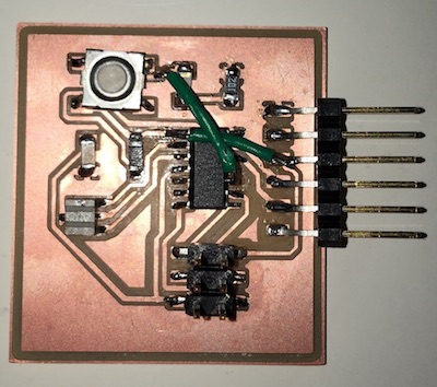
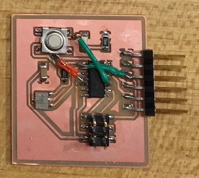
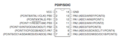
I realized that my circuit design was such that the button press would always light up the led (no programming needed) because pressing the button formed the LED’s connection to VCC. Because the button and LED are hooked up directly to the VCC, there is no way to programmatically control the voltage going to these components. To fix this issue, I added two more jumper wires: one to connect the button to PB2 & another to connect the led to PA3.
…
To program my board I used the following code and followed the same process that I used in order to program my board to echo hello world.
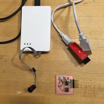
You need
- AVR Atmel Ice programmer
- FTDI <-> usb header
- your programmer
- avrdude installed on your mac
Steps
-
change directories to where your .make and .c files are.
cd ~/Desktop/ -
run make on your make file (the -f option allows you to specify a specific file)
make -f yo.make -
program the fuses on your board so that when it runs the program and communicates, it does so at the right speed.
sudo make -f yo.make program-ice-fuses -
program the board to have the desired funcitonality.
sudo make -f yo.make program-ice
yo.make
PROJECT=yo
SOURCES=$(PROJECT).c
MMCU=attiny44
F_CPU = 20000000

CFLAGS=-mmcu=$(MMCU) -Wall -Os -DF_CPU=$(F_CPU)

$(PROJECT).hex: $(PROJECT).out
	avr-objcopy -O ihex $(PROJECT).out $(PROJECT).c.hex;\
	avr-size --mcu=$(MMCU) --format=avr $(PROJECT).out

$(PROJECT).out: $(SOURCES)
	avr-gcc $(CFLAGS) -I./ -o $(PROJECT).out $(SOURCES)

program-usbtiny: $(PROJECT).hex
	avrdude -p t44 -P usb -c usbtiny -U flash:w:$(PROJECT).c.hex

program-usbtiny-fuses: $(PROJECT).hex
	avrdude -p t44 -P usb -c usbtiny -U lfuse:w:0x5E:m

program-ice: $(PROJECT).hex
	avrdude -p t44 -P usb -c atmelice_isp -U flash:w:$(PROJECT).c.hex

program-ice-fuses: $(PROJECT).hex
	avrdude -p t44 -P usb -c atmelice_isp -U lfuse:w:0x5E:m
yo.c
#include <avr/io.h>
// Import ATTiny44 specific pin names. This general import adjusts based on the processor specified by MMCU in the makefie.

#define button_pin (1 << PB2)
#define led_pin (1 << PA3)

int main(void) {
    // Configure led_pin as an output.
    DDRB |= led_pin;

    // Configure button_pin as an input.
    DDRA &= ~button_pin;

    // Activate button_pin's pullup resistor.
    PORTA |= button_pin;

    while (1) {
        // Turn on the LED when the button is pressed.
        if (PINA & button_pin) {
            // Turn off the LED.
            PORTB &= ~led_pin;
        } else {
            PORTB |= led_pin;
        }
    }

    return 0;
}
test it!
Unfortunately, even though the code uploaded successfully, the led did not turn on when the button was pressed. The voltage coming into the LED is about 1V whereas it should be closer to 3. I do not think this is a software issue, but a hardware issue.
notes
single ended versus differential channels (for analog to digital converter)
- single ended: only ONE low wire, which is shared by all inputs.
- differential channel: A signal input circuit where SIGNAL LO and SIGNAL HI are electrically floating with respect to ANALOG GROUND. For example, a differential input A/D card will have one HI (+) and one LOW (-) pin for each input. There will also be a LLGND (LOW LEVEL GROUND) pin which may be used if a ground connection is required.
- A watchdog timer (WDT) is a hardware timer that automatically generates a system reset if the main program neglects to periodically service it. It is often used to automatically reset an embedded device that hangs because of a software or hardware fault
- a comparator is a device that compares two voltages or currents and outputs a digital signal indicating which is larger. It has twoanalog input terminals and and one binary digital output .
- Universal Serial Interface Channel (USIC) should support various serial protocols like: UART, SPI, IIC and IIS
- SPI Port - short distance communication; what we have on our own chips! uses clk, mosi, miso, ss
- Brown-out - when the power supply voltage dips (potentially due to black outs); it’s good if chips have the ability to detect this because the circuits could be locked up or just give unreliable gibberish results…. so the chip detects it and then resets itself.
- QFN: flat no-leads packages such as quad-flat no-leads (QFN) and dual-flat no-leads (DFN) physically and electrically connect integrated circuits to printed circuit boards.
- MLF: micro lead frame?
- VQFN: Very Thin Quad Flat Non-Leaded Package
SOIC - A Small Outline Integrated Circuit (SOIC) is a surface-mounted integrated circuit (IC) package which occupies an area about 30–50% less than an equivalent dual in-line package (DIP), with a typical thickness being 70% less. They are generally available in the same pin-outs as their counterpart DIP ICs.
PDIP - a dual in-line package (DIP or DIL[1]), or dual in-line pin package (DIPP)[2] is an electronic component package with a rectangular housing and two parallel rows of electrical connecting pins.
UFBGA - ultra fine ball grid array Different kinds of pins on the ATTiny
- SDA: Data line
- SCL: clock line
- OC: output capture
CMOS - Complementary metal–oxide–semiconductor
MIPS - million instructions per second
MCU control register - a processor register which changes or controls the general behavior of a CPU or other digital device. Common tasks performed by control registers include interrupt control, switching the addressing mode, paging control, and coprocessor control. status register is a hardware register that contains information about the state of the processor
Macro Assemblers - macros are useful to providing a shorthand for certain operations (in assembly). The assembler will translate the macros to assembly
Control bus + control lines: it is the control bus that regulates which direction the write and read information need to go. The control bus contains a control line for write instructions and acontrol line for read instructions. When the CPU writes data to the main memory, it transmits a signal to the write command line.
A program counter is a register in a computer processor that contains the address (location) of the instruction being executed at the current time. A stack pointer is a small register that stores the address of the last program request in a stack.
indirect versus direct addressing Indirect addressing uses an address held in a register or other location to determine what memory location to read or write. The idea here is that the instruction itself isn’t directly telling you the address to access, but rather indirectly telling the CPU where to find that address.


