devices that talk to each other
Background
individual assignment: design and build a wired &/or wireless network with addresses connecting at least two processors group assignment: send a message between two projects
To relate this week’s assignment to my final project, i could do any of the following:
- have a wired serial connection across 2 different processors (each taking care of controlling a set of motors).
- have a serial connection between my processor for sensing acceleration and the computer (wired)
- have a wireless connection between the mbed lychee processor interfacing w/ my custom acceleration breakout board.
for 1, i would model off of neils processor and fabricate two of them. for 2. i would create a dedicated board for sensing acceleration (modeled after neil’s) and another board with a processor that will set brightness of the light to match that of the acceleration. Or communicate over wifi to send the acceleration values? for 3. i would fabricate my custom acceleration breakout board.
Serial
Neil showed us a variety of serial bus networks including asynchronous, I2C, SPI, CAN, and USB. The simplest network that Neil showed is the asynchronous one that utilizes the daisy chain, which occurs when there is a single master and multiple children devices share the same line. The most successful serial-data standard for PC and telecom applications is the RS-232. The RS-232 link was initially intended to support modem and printer applications on IBM PCs, however, it now enables a variety of peripherals to communicate with PCs.
Option 1
Based on Neil’s code and circuit designs for the bridge microcontroller board (which has an FTDI header for communicating with the computer) and the node microcontroller board
Design
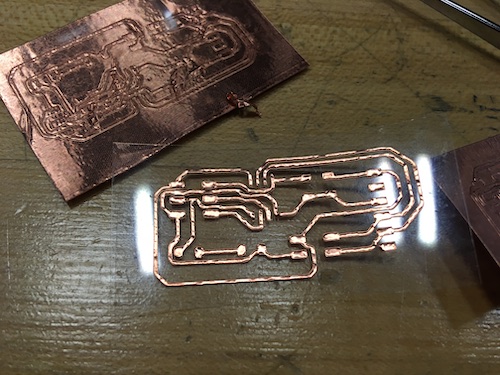
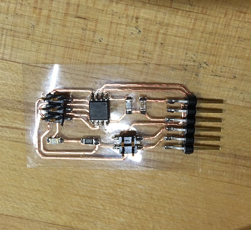
This week, I decided to follow Neil’s serial communication example so I made a similar board using Eagle. The board has an FTDI header for communicating with the computer over serial, an ISP header for programming the board, a 2x2 header for connecting to the serial bus, an ATTiny45 and corresponding pullup resistor and decoupling capacitor, and a green LED and corresponding 499 Ohm resistor.
I wanted to use this week as an opportunity to learn about how to fabricate electronics using the vinyl cutter for the traces. With this in mind, I initially used design rules with too small of a clearance (12 mils) and large traces (20 mils). After vinylcutting some traces and seeing some traces that looked like they were basically touching, I decided to reduce trace width of specific traces that were close to one another to 18 mils. I also increased the clearance to 15 mils so that weeding would be easier.
DRC:
- 18 mil trace width
- 15 mil clearance
Export the png of the traces in monochrome. If exporting from Eagle on Mac, make sure to check the size of the image. You can resize the image using Preview, setting the pixel size to the proper dimensions.

Fabrication
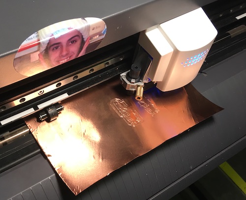
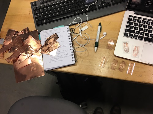
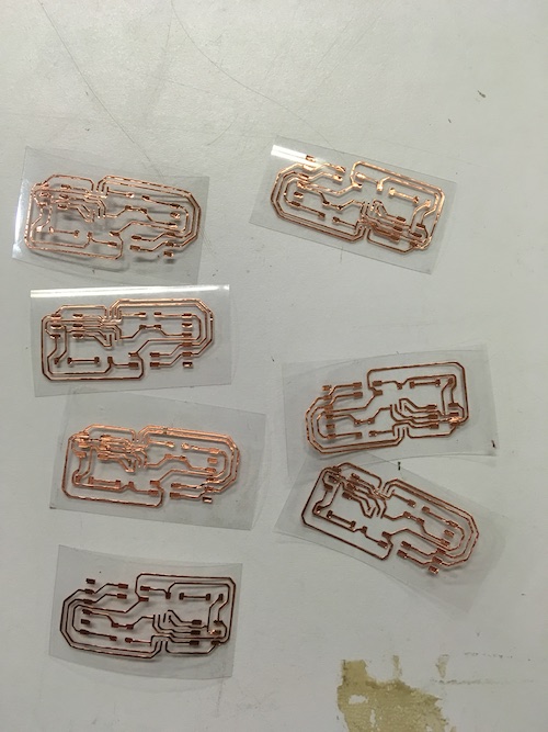
I learned a new fabrication process–vinylcut flexible circuits using copper tape on acetate. This took ~3 hours with multiple interations.
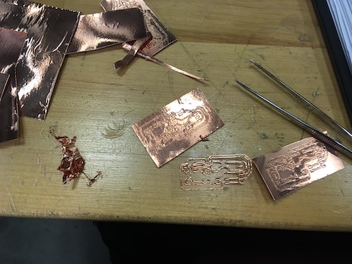
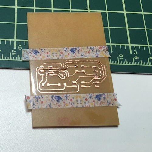
2) plan A) If the print server module is set up & connected to the vinyl cutter, you can pop the png directly into mods (mods > open server program > machines > Roland > vinyl cutter > GX-24 > cut png). plan B) - generate an SVG of the outline of the trace - open svg in CorelDraw to layout the print - use vinylcutter as mentioned in week 2, except with settings: speed 5, force 80. - to troubleshoot - if trace didn’t cut all the way through, clean the blade. - if it says “sheet unloaded” when the sheet is loaded, it might be too small. - to weed (pull outline surrounding trace off of the acetate), try using a pushpin to get under the edge and lift :) works better than tweezers and dull tweezers.
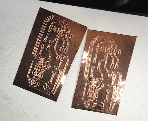
I made a bunch of copies of my board so that I could have backups… especially because I heard that soldering the boards was tricky. In my first iteration, my clearances were low which caused traces to be so close together that 1) I wasn’t confident the circuit would work and 2) it was super difficult to reach in and pull out the copper where the traces were almost touching. I dealt with this by going back into Eagle, setting my clearance to be 15 mils, running DRC (design rule check), ripup-ing the routes that violated the constraint and rerouting accordingly. I also changed the with of a few of my traces from 20 to 18, to give more space between traces in densely packed areas.
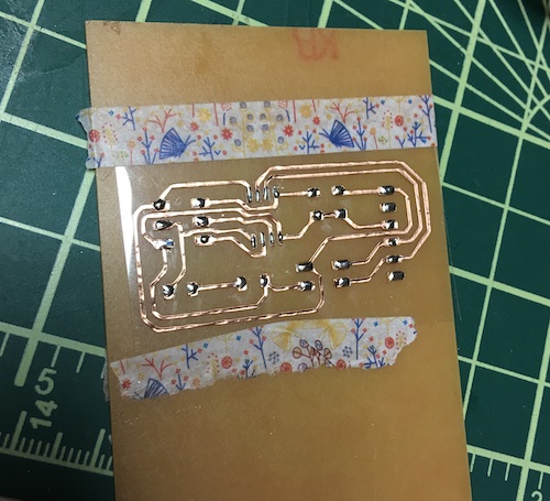
3) soldering/stuffing the board–I was able to do this quickly by tinning the pads and then soldering components in the following order:
- ATTINY45
- Green LED
- 499 Ohm resistor for LED
- 10k Ohm resistor for pullup of reset pin
- 1uF decoupling capacitor
- 2x3 ISP header
- 2x2 header
- FTDI header
Programming
In previous weeks, there have been times where it was necessary to program fuses before actually programming the circuits. But when and why do you program or set fuses. They control things like which oscillator to use, and what speed to run at (ie. the internal 8MHz oscillator, or an external crystal), brownout detection, and the size of the boot flash. As suggested by Elena, I’m going to check out LadyAda’s tutorial on avrdude.
This process turned out to be simpler than I thought it would be. with Neil’s c code and makefile, you change line 31 to however you want to refer to the node. It makes sense to number each node.
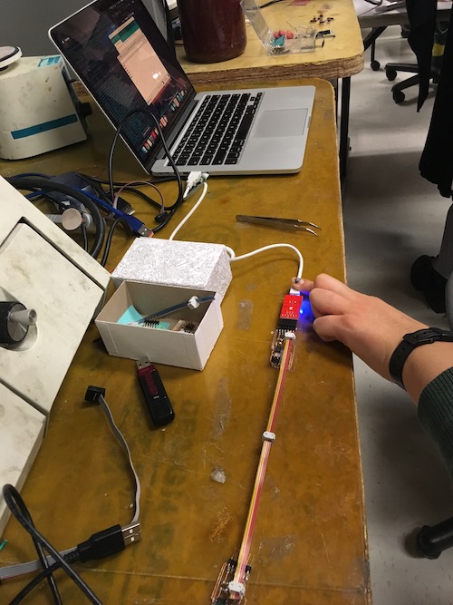
Once your nodes are programmed, you can connect them together and open a serial port connection to them (I did this using Arduino > Tools > Serial Monitor). And start sending commands!
The network is as follows: 1) establish serial connection at port at which your board is connected to usb. I used ftdi <–> microusb module with a microusb to regular usb cable. 2) open serial monitor with the matching port selected. 3) send a message containing which node you’re addressing. 4) in response to the message (which is recieved by all the nodes), each node blinks a light at the same time. 5) if the node id was in the message, then that node will blink another time to indicate that it got the message in addition to sending a message back via serial.