Pre-Meeting
The EECS section met together to discuss teams and machine idea. We decided to split the group into two teams: one would focus on the CAD and fabrication, and the other group would focus on software (embedded and more high level programming).
We debated between a few different ideas for a machine. A couple of the options included a pick and place machine, a mill, a drawing machine (a simplified mill), and a clothes folding machine. Since a clothes folding machine would require image processing, we counted that one out. After a democratic vote, the milling machine won and plans began.
The CAD and fabrication team started designing immediately, and the software team took a few days to look into the code and then started working together over the weekend.
CAD and Fabrication Group
The CAD and Fabrication Group was designated to Prash, Miana, Vivian x 2, Ivan, Marwa, Cowboy. To start, we found some helpful tutorials on Filippos' guide
Day 1 - 11/16
The team assembled in the morning to get together and design the mill. The individual rails and gantries were from Jake, so we just needed to adjust the size parameters and put them all together.
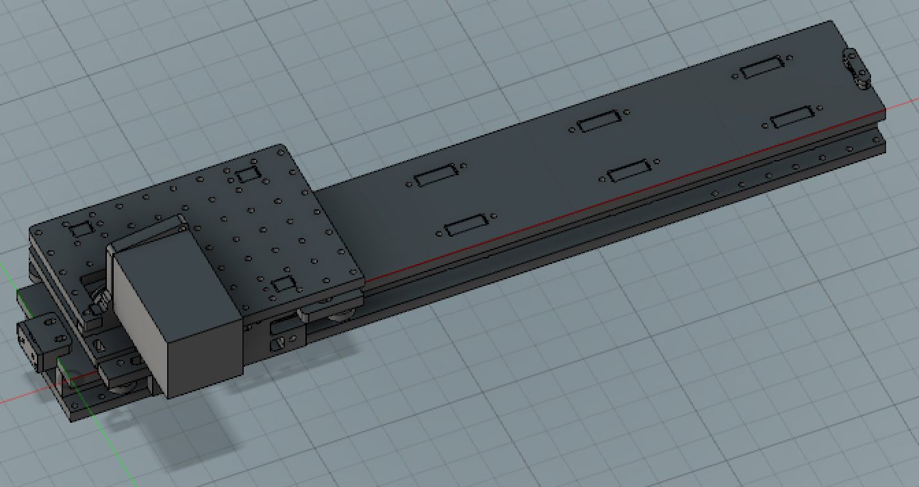
At first, we debated moving the bed in the x-y axis. The cons were that it would require twice as much space per axis as the cutting area. The pros are that we assumed it would be stable. We ultimately decided on spindle moving x-y axis, one stepper each, bed goes along z-axis with two motors. This was a quick decision since we had to get going. In addition, we didn’t want a third axis on spindle because we thought might be too heavy. We spent a couple hours on this design; but it requires a lot of support to hoist the spindle (and xy axis) up high enough. We considered that only one motor along y-axis might cause torque, and that the bed may still be unstable even with two steppers and may flex/tilt
.Our final design was the spindle moving along the xyz axis. This would bring the center of mass way down so that it would be much more stable. We added a base plate for extra accuracy and a bed. We also added:
- Two y rails; each driven by a motor
- x rail attached to y gantries at each end
- z gantry attached to x gantry
- spindle attached to z-rail.
Day 2 - 11/17
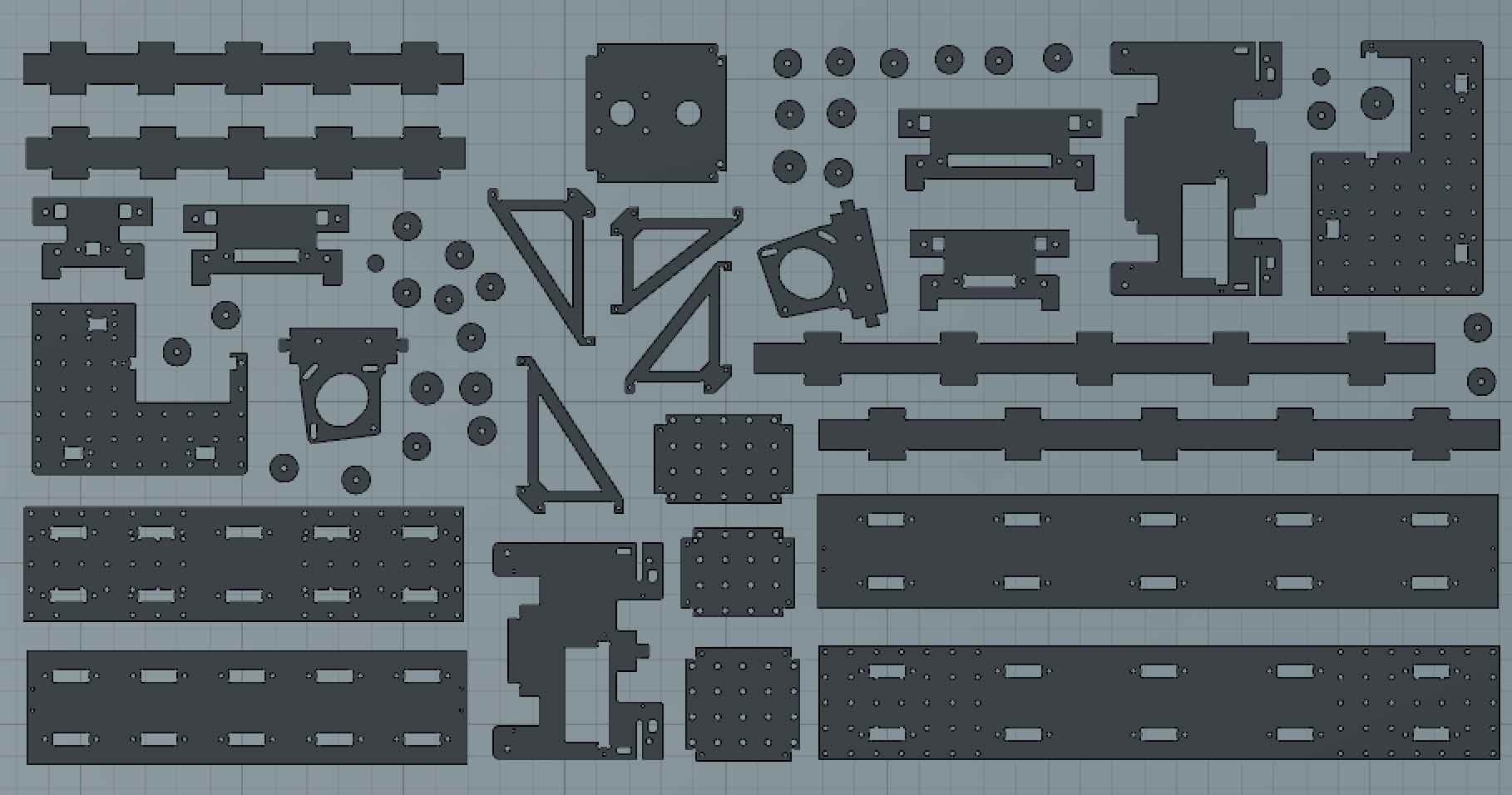
This was the fabrication day, where we met at N51 basement shop to use fancy machine. We found the vacuum bed, automatically switches bits for you; very cool. We used three sheets to cut, and laid design out flat, moved holes to a separate layer but we were confused about exact sizing of holes. So we ended up only drilling the smallest holes; and the other holes were cut out manually. We had problems with CAM software not calculating the right toolpaths. Some pitfalls:
- First board -- broke a bit. Too fast.
- Bed also slightly uneven so some parts came completely detached (supposed to have tabes and a thin layer at the bottom for vacuum bed)
- Only was able to mill on sheet out of three
Day 3 - 11/18
Fabrication day two. Most sheet 1 pieces missing dogbone, so had to add them in via bandsaw or filing (the former option is much faster) Clean up pieces: remove “skirt” and poke through holes with utility knife (very satisfying) Milled the remaining two sheets, seemed to go much better. Added a drilling layer for all the dogbones. Redid pieces that needed redoing - cut on wrong side, missing holes, etc. Seemed to go smoother Broke 3 bits in total @Zach Exported 3D printed components for belt assembly; Ben printed them for us in PLA on his dorm’s LulzBot TAZ 6.
Day 4 - 11/19
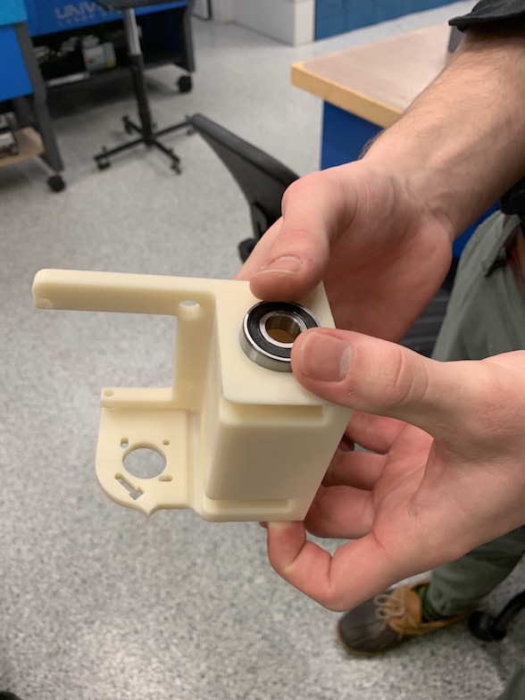
Assembly day! We realized that we have actual metal bearings (yay!) Two of the y rails were smaller (inside cut instead of outside cut) so we had to put them on the bottom and align them very carefully. We drilled holes in the one that didn’t have holes for attachment to base. There was lots of screwing, and power tools make things much easier. There was also lots of countersinking holes for screws to allow pieces to lay flat 3D print parts we were missing: needed 16 bearing cups in total for the belt assembly and only had 3. Printed in pretty red ABS on the Sindoh with the Crystal 1 infill. Overall coming together nicely.
Day 5 - 11/20
Final day! We assembled the rails and put everything together. In post-processing of new 3D printed parts: we couldn’t remove the rafts just by snapping them off — had to use pliers to pry the skirts off instead. Ugly, but they work. The rails were more stable with additional bearing added. Tested belt aligners which seem to be working as intended. We needed to install screws in the gantries to adjust the “preloading force” to control smoothness of the gantries rolling over the rails, and had to move around z-axis.
Software Group
This group consisted of Elliott, Shawn, Leilani, Dylan, Kenny and Nolan. We relied on some useful links from Jake's page on how to make a machine. How to wire things together. Various components and their software:
Chatter software:- circuit chatter
- firmware chatter
- networking software (installing node.js)
- Installing firmware on the ATXMEGAS
- PREPENDIX: Terms of art
- ESC: Electronic speed control
Saturday Updates
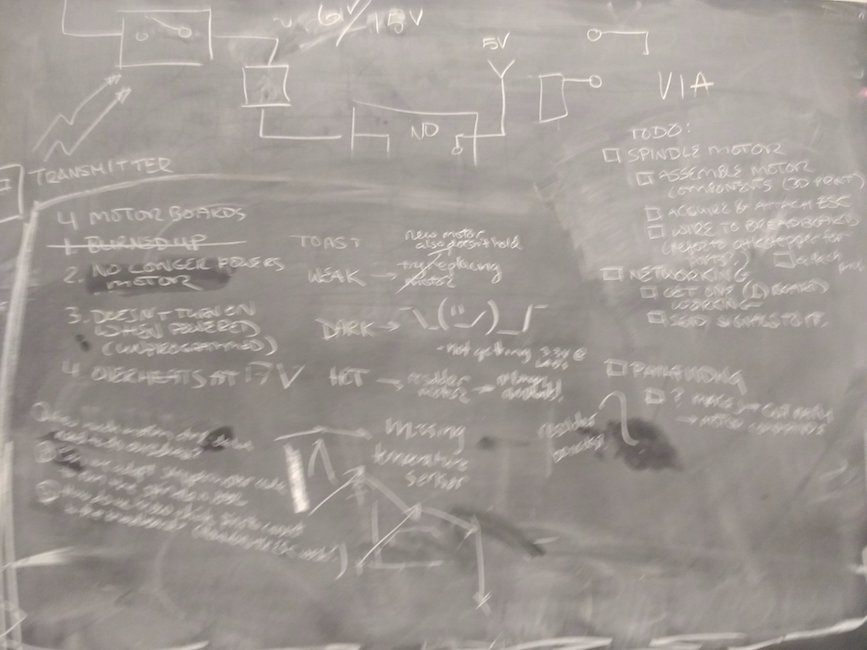
We have one faulty board and are scared by a spark
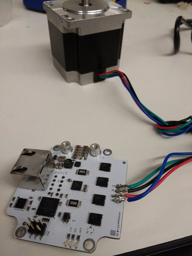
- We have boards which connect to the various motors.
- We solder an ethernet jack and the four wires of the stepper motor to a board. As shown in the video, the four wires of the motor are internally connected to two pairs of pins. You use the multimeter to determine which pairs of wires are connected to each other. Then, you solder them to the board so that connected wires are adjacent to each other: A,A;B,B.
- "Stepper 23" board. Stepper 23 is the type of motor. 23 indicates the size of motor. The board is named after the motor it connect to.
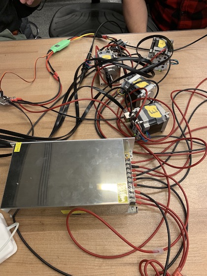
- We have a power supply but do not know how to use it safely. It has screw attachments for AC high, neutral, and low (presumably from the wall), and for DC high out and DC low out. It seems dubious to simply thread wires through screws at wall voltages, so we don't.
- Instead, we retrieve a different power supply that has actual alligator clips. We turn on the machine. We connect V+ to + and gnd to -. The connection sparks, and we turn off the machine. (What we ought to have done was connect the supply first, then turn on the power.)
- We try with a different board (because we didn't initially realize that the spark was a nonfatal problem). Turning on the power supply at 24V creates a jet of grey smoke from a component on the board (which we later determine is the voltage regulator). We turn off the power supply.
- We attempt ramping up from 12V to 24V to see how that fares. At around 20V, it creates additional smoke. We turn off the power supply.
- We test the magnitude and polarity of the voltage being supplied. It is correct.
- We test connectivity of the board itself. The smoky ATK stepper board is 20 Ohms --- oops! at 20V, this is basically a short circuit. In contrast, the other stepper board is 5 M Ohms. It is unclear whether the board was damaged to begin with
- We look at the datasheet for the buck converter. We use a magnifying glass to read the identifier of the component we fried. It is 3001208097.
- We begin to suspect that the spark was a mostly-harmless consequence of the way we turned on the power before attaching leads, rather than attaching before turning on the power. We plug in the board and send power. The light turns on. We prepare to try programming.
- (Our current standing is that we have one fried chip which we will try to replace later, and one apparently-functioning chip that temporarily scared us away by sparking. We have a power supply with screw terminals that we do not know how to use, and another power supply with alligator clips.)
Chapter Two
- Atmel ICE is a programmer. It can talk PDI. Check application notes ("datasheet" for device).
- We download the Atmel programming environment per the instructions on the website, although we resolve to run the workflow through non-proprietary avrdude, time permitting.
- We replace the default (nearly empty) =main.c= file with the =main.c= file supplied by Jake on the website. The circuit doesn't work.
- Within the ATMEL programming environment, we have to manually rebuild the project so that
- XMEGAs don't choose clock sources via fuses. You can change clock source in your startup software.
- Interlude: we learn how to use the screw-terminal power supply. Limiting the strain by taping the wire to the board. Fuse in series with the live wire.
- TA confirms that most multimeters are safely for testing 24V supplies. (Incidentally, For testing wall voltages, one uses a non-contact measurer. It senses field at a distance. For this reason, it only works on AC --- DC produces a magnetic field but the field doesn't change so it can't induce current in a neighboring probe wire.) Atmel development environment has its own standard library which may or may not have a different API. PDI header is proprietary. Connecting to AVR and SAM target devices. The proprietaryness is a property of the programmer; avrdude can probably talk PDI to boards. The way the network works is you plug the router into the computer. It has a ton of ethernet ports on it, and each one connects to a board that controls a motor, whether it's the stepper board or the spindle board (which controls the spinning bit). Stepper 23 boards are made to size to fit the stepper 23 motors. There are sort of free-form modular boards for the spindle motor. So the spindle controller has to be set up in hardware. Router (1), Bread (2), Stepper (4, but one was destroyed)
Data Flow
Network Setup
We have four stepper motors (A, B, C, E) and one spindle motor (spindle). Six things need power: the four stepper motors, the spindle motor, and the spindle motor's electronic speed control (ESC).
Here's an empirical experiment to determine which of our new motors is functioning, attempting to limit external factors. In preparation: Connect the network board to the computer via microusb. Prepare to run rundmc in a terminal. Ensure that power supply will supply more than 12V and less than 24V. Check all cables for connectivity.
- Turn off the power supply, if on.
- Quit the rundmc server, if running.
- Wire motor to power supply.
- Connect motor to network board.
- Turn on power supply.
- Turn on the rundmc server.
- Refresh the browser page.
- Create the atkstepper module.
- Click "Find and connect" to find the tty port.
- Set the address for the stepper module (0,n)
- Send a test network command.
- If successful, send a test motor command.
- Go to step #1.
To test the spindle motor, we attached a ribbon cable to a six-pin header and plugged it in. We used a multimeter (not the best tool for the job but most convenient) to measure the average voltage being send via pulse-width modulation to the spindle motor pins on the breadboard. The middle pin is high; one of the other pins is low; and the third is the signal from the microcontroller. We wanted to measure the difference between the microcontroller signal and ground. From this test it appeared that the pin was not successfully outputting PWM on PC0, and there appeared to be additional potential issues with power connectors, so we finished the evening wallowing in sadness that the spindle motor did not work.
The following day, we determined with an oscilloscope that the issue appeared to be in software rather than hardware - with the default value of 0 successfully set, the firmware was outputting a 1ms pulse over 20ms. However, when inspecting the packets being sent out and received on the network board, it appeared the servoVal was not updating successfully in RNDMC. After some serious debugging work, we found a bug in views.js in which the servoVal of 0 (being falsy) would cause a conditional to fail. We came up with a provisional fix for this, and then found that we were able to control our spindle motor without issue.
Motors
The spindle motor is a special brushless motor. It communicates with the breadboard. Jake has laid out some nice information about the spindle here. At first, we were a bit confused about how everything is laid out and done. The ESC, we learned is the speed control board for the bread board. It look us a bit to figure out that we (1) had the part, and (2) how to use it. Brushless is very different than spindles.
UPDATE - 11/19 we loaded firmware onto the breadboard. We were also surprised to find out that we would need to 3D print. We ended up using the nice printers. We hadn't realized that the 40T/12mm bore pulley needed to be printed, and was not included in the parts ordered. The .stl was in the simplespindle repo. We were also missing some disc springs, but apparently, they aren't crucial to the spindle so it was ok to omit them (but they make it run a bit smoother).
Some pitfalls
- Fried a board early on
- Forgot to 3D print some parts of the spindle motor carriage until late Monday (didn’t read the documentation as well as we should have).
- Also, this happened the first time we powered the spindle motor higher than ~10% (warning: may be loud)
Putting It All Together
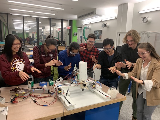
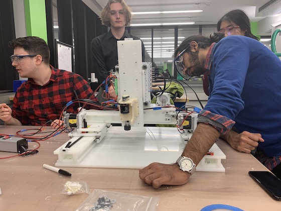
We had to change the G-code to be able to do two of the y-components at once. We also had to strap some of the wires together for safety, but in general, it worked! Below is a slow-motion video of our actual real-life machine's actuation in action!
The Memes