04
ELECTRONICS DESIGN
This week we worked on designing a circuit, but this time completely from scratch.
| Tools: | Eagle, Photoshop, SRM-20 |
| Files: | Board - Eagle Project |
| Date: | 10.10.2018 |
Design Process
I decided to use Eagle to design my PCB since I've worked mostly with Solidworks before and the two are intended to play nicely together. I soon discovered that Eagle is a lot harder to use then it lets on.
My first mistake was not having a strong foundation in Eagle. I had missed the recitation because of a prior conflict and was left feeling confused. Thankfully, after some help from my TAs, I was caught up in the basics.
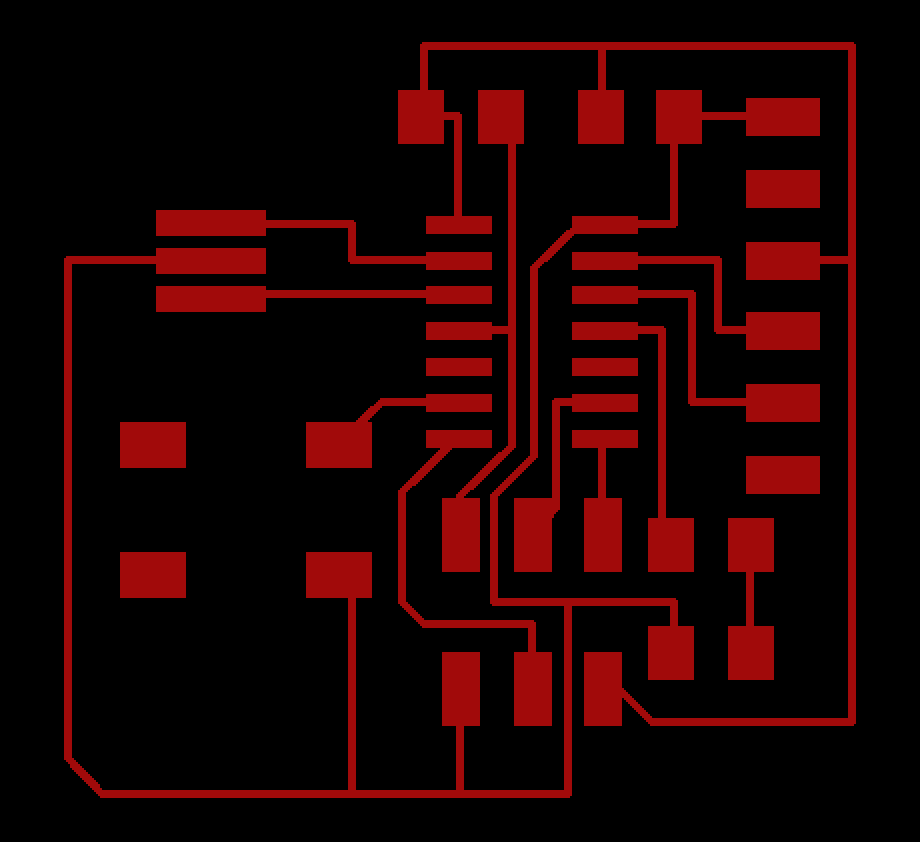
After following the board design here and adding my own LED and button, this was the result.
Milling
Unfortunately, here is where I ran into a lot of issues. The first was that there is a retina display issue on MAC such that my exported images from Eagle were actually twive as large as they needed to be. I waited the whole time for the milling to complete before recognizing this issue and finally fixing it. The way to fix this is when using mods to double the dpi so that actual size of the image ends up being the same.
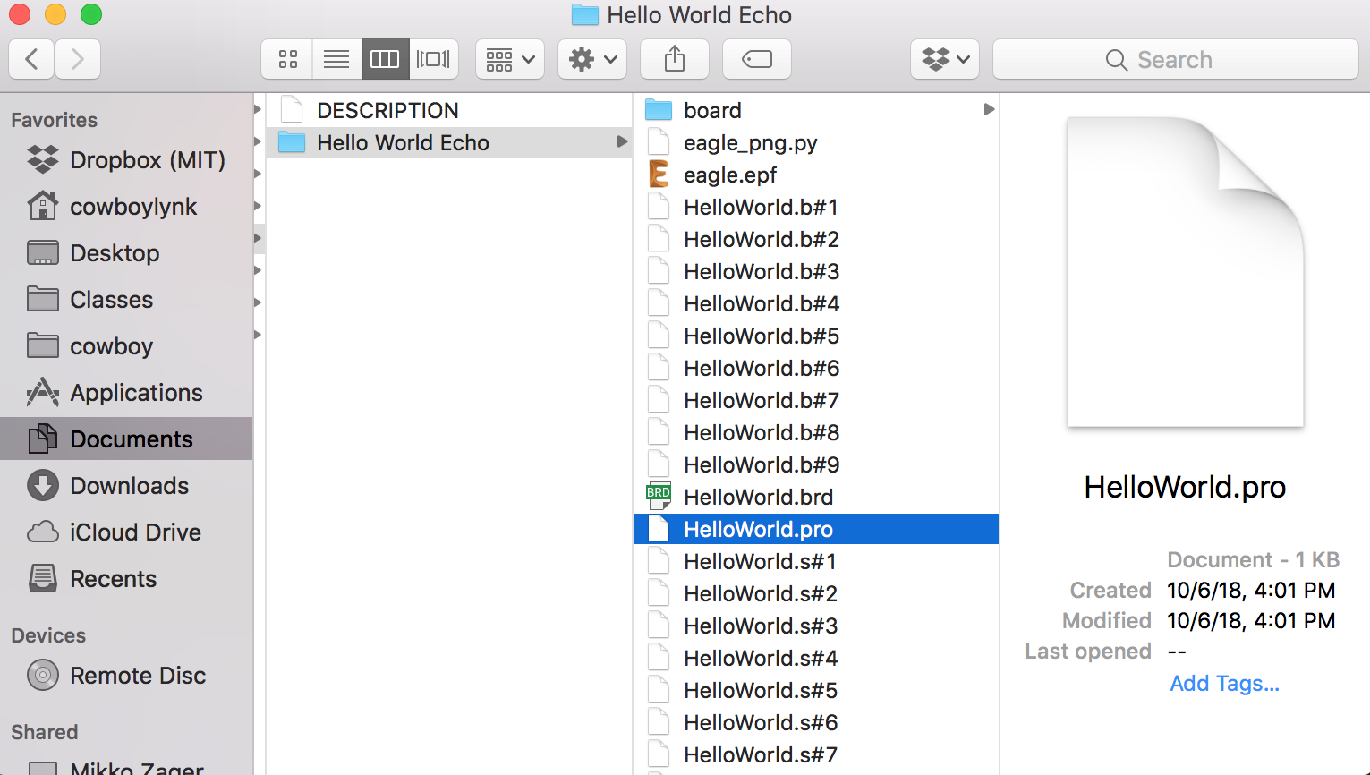
After that I noticed that the image I was exporting was not being milled properly. Even though I was using the fab design rules for Eagle, I continuously ran into the issue that the mill would not go through certain areas. After hours of confusion, I finally figured out that if I used the script (instead of going directly our of Eagle) to export images this issue didn't happen. I'm still not exactly sure why.
Getting the script to run came with a few problems of its own. I was getting an error that the script couldn't find certain layers in my board. The fix for this was to put the .brd file into it's own folder. I'm still not sure why that worked, but I'll do some more research on this later.
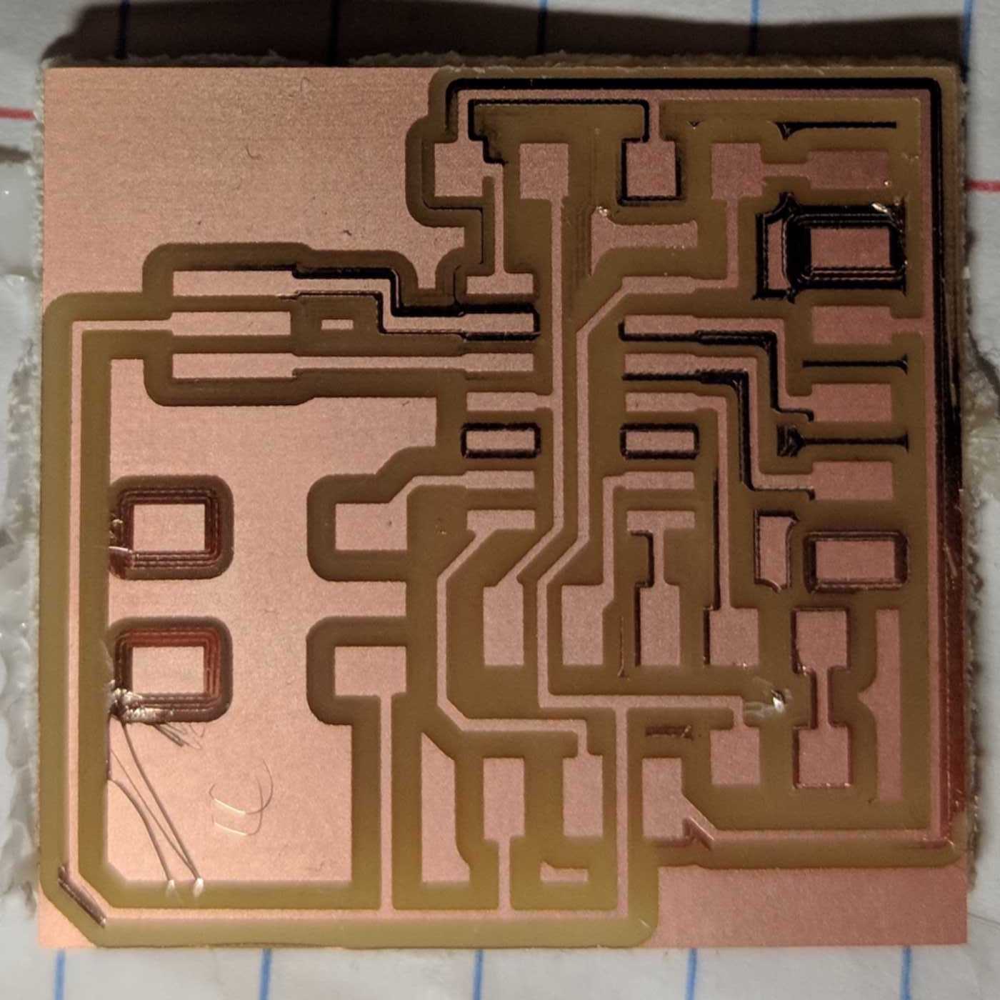
Finally I have a milled board, but right as I was begining to solder, I noticed that some of the cuts did not go all the way through and that they would probably cause shorts. I plan to go back and fix this later this week.
Soldering
I finally had some time to solder all the componenets on. This process took me a very long time and was incredibly frustrating. Soldering on the ATTiny44 was particularly stress-inducing. At first, I tried Neil's approach of adding solder to all the joints without worrying about shorts. The plan was to attach the ATTiny44 and then remove solder inbetween joints with the braid. Unfortunately, this didn't work at all for me. I tried removing the solder completely and going at it again with a new ATTiny44, but ultimately decided to just mill a new board.
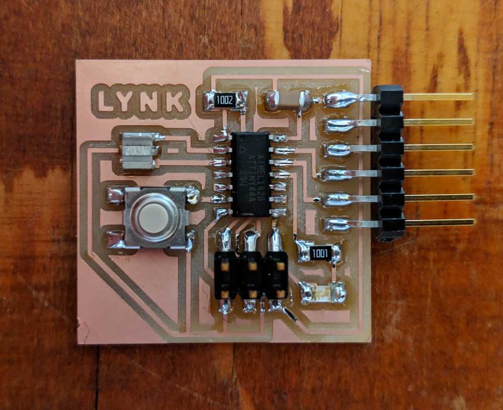
With this new board, I started soldering using the standard techniques and with some help from Zach, I was able to figure out a strategy that works well for me. I have yet to test this board, but hopefully everything is soldered properly and there are no issues with programming.
Programming
I did a priliminary test with a volt meter to ensure that the board was getting 5V. Additionally I checked continuity test on a pad that I was a little bit worried about. I had to desolder a component and accidentally removed some of the copper pad. The continuity test was just to make sure that everything was still connected.
Now with the board ready, I got my programmer out and plugged in everything. I started following the programming steps on this image. But soon after, I ran into the dreaded rc=-1 error. After some detective work, we concluded that my board and programmer were both fine, it was actually just my computer (Macbook Pro) having an issue with my programmer. Using a different programmer or doing everything on a seperate computer worked just fine.
With the program ready, I needed to now setup a serial terminal. On MacOSX you do that in the following way: screen /dev/tty.usbserial-XXXXXXXX 115200 -L. Here's the final result.