08
INPUT DEVICES
This week we worked on input devices. I focused on the Hall effect sensor that I'll later use to 'home' my final project.
| Tools: | Eagle, Roland Mill |
| Files: | Hall effect sensor - code |
| Date: | 11.07.2018 |
Ideas
I am now finally starting to start work towards my final project. My final project idea involves moving a loose bearing ball around a table of sand by controlling it with a strong magnet at the end of a polar plotter hidden below the table. One of the challenges I foresee with this design is 'homing' it when the device is turned on or off.
For the polar axis this can simply done using a IR sensor where a piece of plastic breaks the IR signal once per rotation. The radial axis is a little trickier. Since my design already incorporates a magnet at the end of the polar plotter, I figure that I can use a hall effect sensor to find 'home' relatively easily.
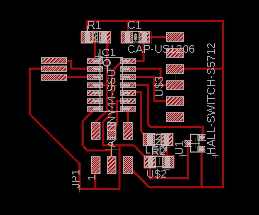
The Design
I designed a PCB in Eagle and had so much of an easier time getting everything done now that I had already gone through all the struggles of debugging in week 04.
Nothing is too special about the design, I just took the design files from week 04, removed the button, and added the hall effect sensor.
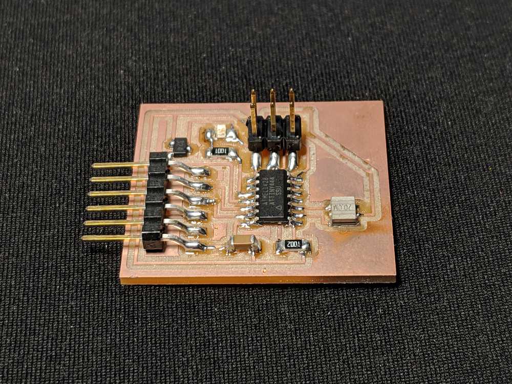
Soldering
This was probabily the quickest I've ever soldered something and I'm so happy with how it turned out. The trick was just to keep cleaning the soldering iron and applying a little bit of solder. Doing made it so that all of my joints were nice and smooth and I never had to deal with any shorts.
I did mess up the direction of the LED for the third time this semester so now I'm writing it down now so I don't forget. The knob on the bottom points towards ground.
Testing
One of the challenges this week was getting the ATTiny to communicate with the Arduino IDE. Following online tutorials wasn't getting me anywhere and any time I opened the serial monitor I just saw nothing even though I knew my code was running (the LED was working as expected).
I soon found out that it had to do with setting my clock speed and baud rate to the right values. I'll have to do some further investigating, but it seems that communication only works when I set the clock rate to be 'Internal 8 MHz' and the baud rate to be '1200.'
#include <SoftwareSerial.h>
#define RX    1
#define TX    0

// ***
// *** Define the software based serial port. Using the
// *** name Serial so that code can be used on other
// *** platforms that support hardware based serial. On
// *** chips that support the hardware serial, just
// *** comment this line.
// ***
SoftwareSerial Serial(TX, RX);

const int LED_PIN = 3;
const int HALL_PIN = 2;

// the setup function runs once when you press reset or power the board
void setup() {
  Serial.begin(1200);
  Serial.println("Initializing...");

  // initialize digital pin LED_BUILTIN as an output.
  pinMode(LED_PIN, OUTPUT);
  pinMode(HALL_PIN, INPUT_PULLUP);
  digitalWrite(LED_PIN, LOW);
}

int led_state = 0; // 0 = off, 1 = on

// the loop function runs over and over again forever
void loop() {
  int hall = analogRead(HALL_PIN);
  Serial.println(hall);
  if (hall > 700){
    led_state = 1;
  } else {
    led_state = 0;
  }

  digitalWrite(LED_PIN, led_state);
  delay(50);
}
When I finally got the communication working I was able to see the threshold for when the sensor detects enough magnetic field to when I think the LED should trigger. Here's what that looks like. Notice how in the video on the left the numbers change from the 700s to the 500s when I move the sensor away from a magnet (the magnet is inside my computer).