12
NETWORKING AND COMMUNICATION
This week we worked on networking and communication. I designed and made the boards that I'll be using in my final project. I will have one main board that communicates to two breakout boards (with their own processors) and tells them what to do. This will be useful so that I can have the two boards for the stepper motors in seperate locations.
| Tools: | Eagle, Roland Mill |
| Date: | 12.05.2018 |
Ideas
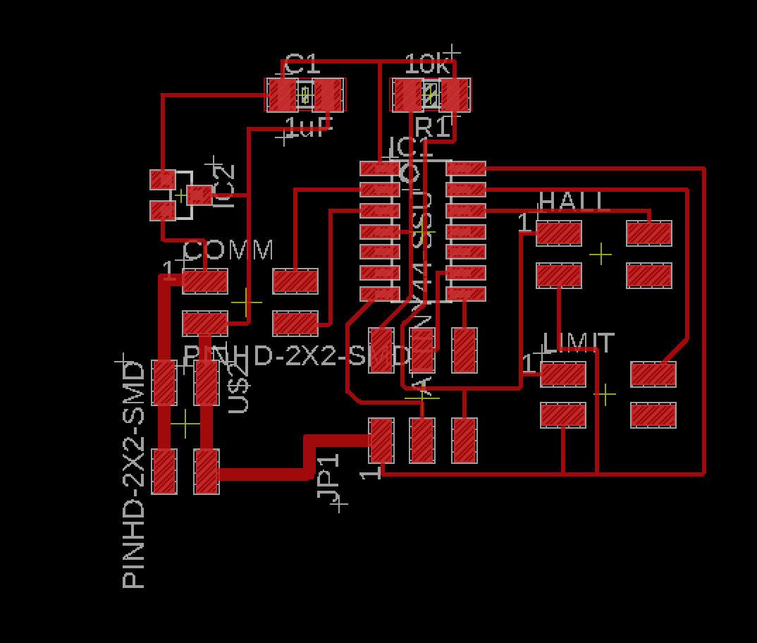
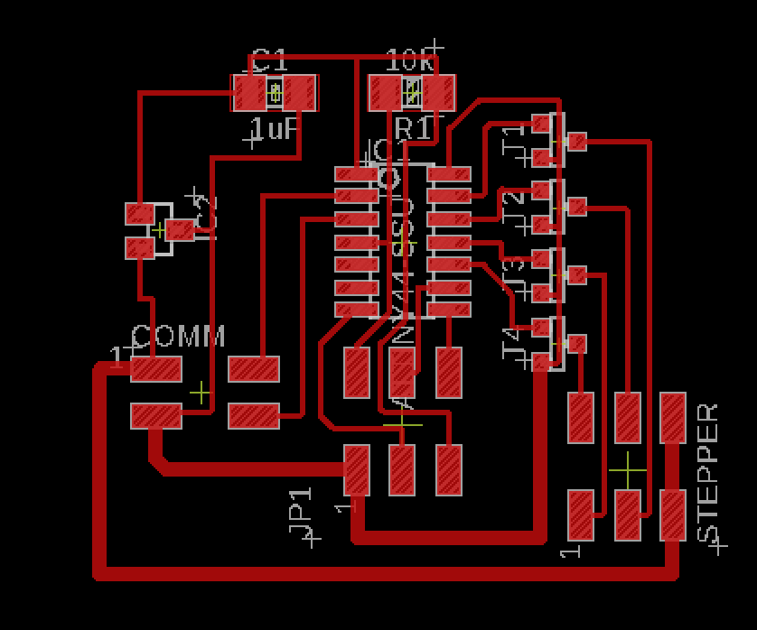
Below you can see two board designs. The one on the left is the main board that does all of the computations for how the two motors should move. It also has two 2x2 headers that will connect to a limit switch and a hall effect sensor to help orient the axis. On the right is the board that actually controls the stepper motor. You can see the H-bridge design that allows the motor to move both forward and backwards.
Communication
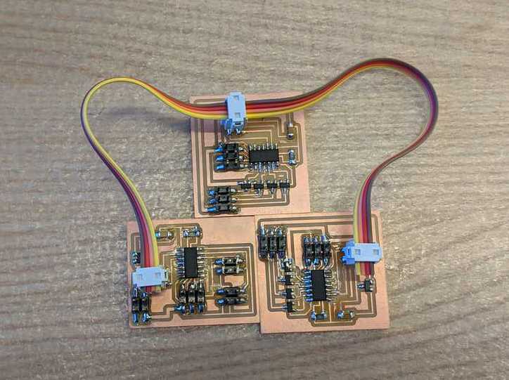
I used Neil's asyncronous board design as a template for how I want my boards to communicate. As seen in the images above and the one below, there is one main board that sends out commands and two node boards that recieve those messages. The two nodes have addresses and so they only respond if the main board is sending the message to their address (but they still see every message because all of the communication wires are connected).
The two node boads each have a 3x2 pin connection where I will attach stepper motors. For a preliminary test of communications I wanted to see if I could toggle the motors on and off by using the main board to tell which of the node boards to be on. In other words, I send a command to a node telling it to turn on and start taking steps. The motor should keep taking steps until it sees a command for another address. At this point it knows to shut off and wait until it's told to turn on again.
On the left you can see the a snippet of code running on the main board. What it does is alternate between sending 0 and 1 (the two addresses of the node boards). On the right you can see the piece of code responsible for deciding when to turn on and off the motor. First it checks that the reading is not 255. 255 just means that there is nothing to read. And then it checks if the sent bit matches it's own address.
byte x = 0;

void loop() {
MySerial.write(x);
x = 1 - x;
delay(1000);
}
int shouldStep = 1;
byte addr = 1;
byte v = 0;
void loop()
{
  v = int(MySerial.read());
  if (v != 255) {
    if (v == addr){
      shouldStep = 1;
    } else {
      shouldStep = 0;
    }
  }

  if (shouldStep){
    stepper.step(1);
  }
}