Networking notes
Table of Contents
I design and build a board to talk to my infrared camera over TWI
(I2C). Initially, I use Neil's hello.bus.45.bridge board design with
the attiny45
[http://academy.cba.mit.edu/classes/networking_communications/index.html],
and program with a modified version of the hello.ADXL343 I2C
accelerometer code from inputs week
[http://academy.cba.mit.edu/classes/input_devices/index.html]. Then I
switch to the atmega328p. Because I use the atmega328p chip, I take
advantage of the built-in TWI capability (i.e. using registers instead
of bit-banging). Details follow.
1 TWI (I2C) Code
This was my first board using the atmega328p (which is the same chip
used in arduino boards). To get the appropriate compilation settings,
I borrowed the hello.arduino.328p.blink code
[http://academy.cba.mit.edu/classes/embedded_programming/index.html].
For the TWI (I2C) code, I initially used various TWI libraries and
then eventually manipulated the registers myself because it seemed
simpler and more direct. Importantly, I learned how to include
external libraries in this process (Add the library C files to your
SOURCES variable in the makefile, and import the header files in
your main C program.)
# File: dxh.hello.twi.make
PROJECT=dxh.hello.twi
SOURCES = $(PROJECT).c \
#               twimaster.c
#               i2c_master.c
MMCU=atmega328p
F_CPU = 20000000
# F_CPU = 16000000UL

CFLAGS=-mmcu=$(MMCU) -Wall -Os -DF_CPU=$(F_CPU)
# note std=gnu99 for for-inital declarations in library

$(PROJECT).hex: $(PROJECT).out
        avr-objcopy -O ihex $(PROJECT).out $(PROJECT).c.hex;\
        avr-size --mcu=$(MMCU) --format=avr $(PROJECT).out

$(PROJECT).out: $(SOURCES)
        avr-gcc $(CFLAGS) -I./ -o $(PROJECT).out $(SOURCES)

program-bsd: $(PROJECT).hex
        avrdude -p atmega328p -c bsd -U flash:w:$(PROJECT).c.hex

program-dasa: $(PROJECT).hex
        avrdude -p atmega328p -P /dev/ttyUSB0 -c dasa -U flash:w:$(PROJECT).c.hex

program-avrisp2: $(PROJECT).hex
        avrdude -p atmega328p -P usb -c avrisp2 -U flash:w:$(PROJECT).c.hex

program-avrisp2-fuses: $(PROJECT).hex
        avrdude -p atmega328p -P usb -c avrisp2 -U lfuse:w:0x56:m
        avrdude -p atmega328p -P usb -c avrisp2 -U hfuse:w:0xD9:m
        avrdude -p atmega328p -P usb -c avrisp2 -U efuse:w:0x07:m

program-usbtiny: $(PROJECT).hex
        avrdude -p atmega328p -P usb -c usbtiny -U flash:w:$(PROJECT).c.hex

program-usbtiny-fuses: $(PROJECT).hex
        avrdude -p atmega328p -P usb -c usbtiny -U lfuse:w:0x56:m
        avrdude -p atmega328p -P usb -c usbtiny -U hfuse:w:0xD9:m
        avrdude -p atmega328p -P usb -c usbtiny -U efuse:w:0x07:m

program-dragon: $(PROJECT).hex
        avrdude -p atmega328p -P usb -c dragon_isp -U flash:w:$(PROJECT).c.hex

program-ice: $(PROJECT).hex
        avrdude -p atmega328p -P usb -c atmelice_isp -U flash:w:$(PROJECT).c.hex

program-ice-fuses: $(PROJECT).hex
        avrdude -p atmega328p -P usb -c atmelice_isp -U lfuse:w:0x56:m
        avrdude -p atmega328p -P usb -c atmelice_isp -U hfuse:w:0xD9:m
        avrdude -p atmega328p -P usb -c atmelice_isp -U efuse:w:0x07:m
// dxh.hello.twi.c

#include <avr/io.h>
#include <util/delay.h>
#include <avr/pgmspace.h>

// library from https://github.com/g4lvanix/I2C-master-lib
// #include "i2c_master.h"

// library from https://github.com/alx741/avr_i2c
#include <i2cmaster.h>


#define output(directions,pin) (directions |= pin) // set port direction for output
#define set(port,pin) (port |= pin) // set port pin
#define clear(port,pin) (port &= (~pin)) // clear port pin
#define pin_test(pins,pin) (pins & pin) // test for port pin
#define bit_test(byte,bit) (byte & (1 << bit)) // test for bit set

#define bit_delay() _delay_us(bit_delay_time) // RS232 bit delay
#define half_bit_delay() _delay_us(bit_delay_time/2) // RS232 half bit delay
#define char_delay() _delay_ms(10) // char delay


//#define bit_delay_time 8.5 // bit delay for 115200 with overhead
//#define bit_delay_time 8.5 // bit delay for 115200 with overhead
//#define bit_delay_time 8.5 // bit delay for 115200 with overhead
#define bit_delay_time 102 // 9600
// 7.4 ---

/* // from the computer perspective, out (from comp) in (to comp) */
#define serial_port PORTD
#define serial_direction DDRD
#define serial_pins PIND
#define serial_pin_in (1 << PD1)
#define serial_pin_out (1 << PD0)

#define led_port PORTC
#define led_direction DDRC
#define led_pin_1 (1 << PC1)
#define led_pin_2 (1 << PC0)
#define led_delay() _delay_ms(100) // LED delay

#define IR_CAMERA_ADDRESS 0xB0 // 8 bit address (0x58 << 1)

#define max_buffer 25

void get_char(volatile unsigned char *pins, unsigned char pin, char *rxbyte) {
   //
   // read character into rxbyte on pins pin
   //    assumes line driver (inverts bits)
   //
   *rxbyte = 0;
   while (pin_test(*pins,pin))
      //
      // wait for start bit
      //
      ;
   //
   // delay to middle of first data bit
   //
   half_bit_delay();
   bit_delay();
   //
   // unrolled loop to read data bits
   //
   if pin_test(*pins,pin)
      *rxbyte |= (1 << 0);
   else
      *rxbyte |= (0 << 0);
   bit_delay();
   if pin_test(*pins,pin)
      *rxbyte |= (1 << 1);
   else
      *rxbyte |= (0 << 1);
   bit_delay();
   if pin_test(*pins,pin)
      *rxbyte |= (1 << 2);
   else
      *rxbyte |= (0 << 2);
   bit_delay();
   if pin_test(*pins,pin)
      *rxbyte |= (1 << 3);
   else
      *rxbyte |= (0 << 3);
   bit_delay();
   if pin_test(*pins,pin)
      *rxbyte |= (1 << 4);
   else
      *rxbyte |= (0 << 4);
   bit_delay();
   if pin_test(*pins,pin)
      *rxbyte |= (1 << 5);
   else
      *rxbyte |= (0 << 5);
   bit_delay();
   if pin_test(*pins,pin)
      *rxbyte |= (1 << 6);
   else
      *rxbyte |= (0 << 6);
   bit_delay();
   if pin_test(*pins,pin)
      *rxbyte |= (1 << 7);
   else
      *rxbyte |= (0 << 7);
   //
   // wait for stop bit
   //
   bit_delay();
   half_bit_delay();
   }

void put_char(volatile unsigned char *port, unsigned char pin, char txchar) {
   //
   // send character in txchar on port pin
   //    assumes line driver (inverts bits)
   //
   // start bit
   //
   clear(*port,pin);
   bit_delay();
   //
   // unrolled loop to write data bits
   //
   if bit_test(txchar,0)
      set(*port,pin);
   else
      clear(*port,pin);
   bit_delay();
   if bit_test(txchar,1)
      set(*port,pin);
   else
      clear(*port,pin);
   bit_delay();
   if bit_test(txchar,2)
      set(*port,pin);
   else
      clear(*port,pin);
   bit_delay();
   if bit_test(txchar,3)
      set(*port,pin);
   else
      clear(*port,pin);
   bit_delay();
   if bit_test(txchar,4)
      set(*port,pin);
   else
      clear(*port,pin);
   bit_delay();
   if bit_test(txchar,5)
      set(*port,pin);
   else
      clear(*port,pin);
   bit_delay();
   if bit_test(txchar,6)
      set(*port,pin);
   else
      clear(*port,pin);
   bit_delay();
   if bit_test(txchar,7)
      set(*port,pin);
   else
      clear(*port,pin);
   bit_delay();
   //
   // stop bit
   //
   set(*port,pin);
   bit_delay();
   //
   // char delay
   //
   bit_delay();
   }

void put_string(volatile unsigned char *port, unsigned char pin, char *str) {
   //
   // print a null-terminated string
   //
   static int index;
   index = 0;
   do {
      put_char(port, pin, str[index]);
      ++index;
      } while (str[index] != 0);
   }


void example_echo() {
   static char chr;
   static char buffer[max_buffer] = {0};
   static int index;

  //
   // main loop
   //
   index = 0;
   while (1) {

     clear(led_port, led_pin_1);
     get_char(&serial_pins, serial_pin_in, &chr);
     set(led_port, led_pin_1);

      put_string(&serial_port, serial_pin_out, "hello.ftdi.44.echo.c: you typed \"");
      buffer[index++] = chr;
      if (index == (max_buffer-1))
        index = 0;
      put_string(&serial_port, serial_pin_out, buffer);
      put_char(&serial_port, serial_pin_out, '\"');
      put_char(&serial_port, serial_pin_out, 10); // new line
   }
}


void example_blink() {
  while(1) {
    set(led_port, led_pin_1);
    clear(led_port, led_pin_2);
    led_delay();
    clear(led_port, led_pin_1);
    set(led_port, led_pin_2);
    led_delay();
  }

}


void twi_init_camera() {
  unsigned char data[16];
  int error = 0;

  // sequence:
  // 11 both lights on initially
  // 00 both lights off after 1s delay
  // 01 success initiating i2c
  // 11 success sending first message
  // 01 success sending all messages

  clear(led_port, led_pin_1);
  clear(led_port, led_pin_2);
  output(led_direction, led_pin_1);
  output(led_direction, led_pin_2);


  set(led_port, led_pin_1);
  set(led_port, led_pin_2);
_delay_ms(1000); // essential delay for camera's microprocessor startup
  clear(led_port, led_pin_1);
  clear(led_port, led_pin_2);

  put_char(serial_port, serial_pin_out, 'a');


  if (i2c_start_wait(IR_CAMERA_ADDRESS) == 0)  {
    // success
      set(led_port, led_pin_1);

    // Infrared sensor handshake/incantation..
   //
   // This sequence sends (control_register_address, data) pairs to
   // the computer onboard the infrared camera. Its purpose is to
   // specify the sensitivity of the camera.
   //

    data[0] = 0x30;
    data[1] = 0x01;


    error |= i2c_transmit(IR_CAMERA_ADDRESS, data, 2);


    if(error == 0) {

      // successful first transmission
      set(led_port, led_pin_2);
    }


    data[0] = 0x30;
    data[1] = 0x08;
    error |= i2c_transmit(IR_CAMERA_ADDRESS, data, 2);


    data[0] = 0x06;
    data[1] = 0x90;
    error |= i2c_transmit(IR_CAMERA_ADDRESS, data, 2);

    data[0] = 0x08;
    data[1] = 0xC0;
    error |= i2c_transmit(IR_CAMERA_ADDRESS, data, 2);

    data[0] = 0x1A;
    data[1] = 0x40;
    error |= i2c_transmit(IR_CAMERA_ADDRESS, data, 2);

    data[0] = 0x33;
    data[1] = 0x33;
    error |= i2c_transmit(IR_CAMERA_ADDRESS, data, 2);
   //i2c_stop();

    if( error == 0) {
      // all messages sent! 01
      clear(led_port, led_pin_1);
      set(led_port, led_pin_2);
    }
  }


void example_twi() {
  unsigned char data[16];
  int error = 0;


  _delay_ms(100);
  _delay_ms(100);
  _delay_ms(100);
  _delay_ms(100);
  _delay_ms(100);

  put_string(&serial_port, serial_pin_out, "abcd");

  // send START condition

  // TWEN: enable twi
  // TWSTA: desire to become master. must be cleared after start transmitted.
  // TWINT: twi interrupt, pulls the clock down. must be cleared by writing 1.

  TWCR = 0;
  TWCR =  (1 << TWEN) | (1<<TWSTA) | (1<<TWINT); // send i2c initialization; blocks until success.

  // report success
  while(1) {
    put_string(&serial_port, serial_pin_out, "a");
  }


}

int main(void) {
   //
   // main
   //
   // set clock divider to /1
   //
   CLKPR = (1 << CLKPCE);
   CLKPR = (0 << CLKPS3) | (0 << CLKPS2) | (0 << CLKPS1) | (0 << CLKPS0);

   //
   // initialize output pins
   //
   set(serial_port, serial_pin_out);
   output(serial_direction, serial_pin_out);

   output(led_direction, 1 << PC0);
   output(led_direction, 1 << PC1);

   example_twi();
}
2 Log
I have an infrared positioning camera. It is like the camera used in Wii remotes. It has built-in circuitry for detecting up to four moving points; it reports those points, and doesn't report image data at all.
Digikey: 1738-1250-ND "Datasheet": https://media.digikey.com/pdf/Data%20Sheets/DFRobot%20PDFs/Positioning_IR_Camera_Web.pdf Wiimote IR camera: http://wiibrew.org/wiki/Wiimote#IR_Camera
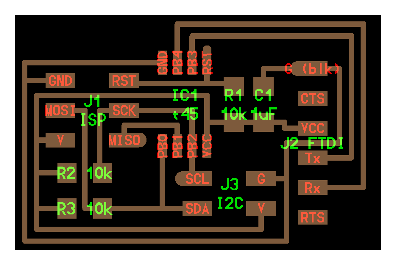
For the camera circuit, I made Neil's I2C-bridge (see: networking I2C page). It uses the little Tiny45 processor.
Plugging in the camera requires knowing which of the four colored wires on the camera belong on which of the four pins of the I2C pin header. Compare:
Label on camera surface: Red:VCC, Black:GND, Green:SCL, Yellow:SDA
For programming the camera circuit, I used the accelerometer "bit banging" C code as a template.
The desired baud rate for communication changes certain parameters in the C code. Specifically,
bit_delay_timeis set based on the baud rate. By looking at Neil's various files, I've found that the recommended bit delays (with overhead) are:baud rate bit delay 115200 8.5 19200 49.5 9600 102 Of course, an oscilloscope would help refine those values for your circuit in particular.
According to the datasheet, the camera transmits data at a high
rate, and so serial communication between the board and the computer
should be similarly fast, at 19200—double the accelerometer's baud
rate of 9600. So I change the definition of bit_delay_time
accordingly.
Do I need to adapt the C code because the pin usage is different between the accelerometer and the I2C bridge? Another table:
pin In accelerometer code In I2C bridge diagram PB0 MOSI MOSI / I2C SDA PB1 MISO MISO PB2 SCK/Rx I2C SCL PB3 I2C SCL Tx PB4 I2C SDA Rx Okay, so yeah. A lot of pin definitions have changed.
- Rx changes from PB2 to PB4.
- SCL changes from PB3 to PB2.
- SDA changes from PB4 to PB0
Building off of my interface week code (
hello-serial.js), I made a new function for parsing the encoded serial input from the camera.infrared_camera_terminal = function() { // Speak with a PCB board that is speaking with an infrared // positioning camera. (part id: 1738-1250-ND) // Set up serial connection const SerialPort = require('serialport') const Readline = require('@serialport/parser-readline') const port = new SerialPort(serial_port, {baudRate: baud, databits:8, dtr: true, }) var stream = [] var pos_x = new Array(4) var pos_y = new Array(4) var upper_bits var index = null // Serial-opening errors will be emitted as an error event port.on('error', function(err) { console.log('Error: ', err.message) }) // Whenever serial data is received, interpret the data as // the special format of the infrared positional camera. var process_ir_data = function() { while( stream.length >= 16 ) { stream.shift() // Look for framing data if( stream[0] == 1 && stream[1] == 2 && stream[2] == 3 && stream[3] == 4 ) { pos_x[0] = stream[4] pos_y[0] = stream[5] upper_bits = stream[6] pos_x[0] += (upper_bits & 0b00110000) << 4; pos_y[0] += (upper_bits & 0b11000000) << 2; pos_x[1] = stream[7] pos_y[1] = stream[8] upper_bits = stream[9] pos_x[1] += (upper_bits & 0b00110000) << 4; pos_y[1] += (upper_bits & 0b11000000) << 2; pos_x[2] = stream[10] pos_y[2] = stream[11] upper_bits = stream[12] pos_x[2] += (upper_bits & 0b00110000) << 4; pos_y[2] += (upper_bits & 0b11000000) << 2; pos_x[3] = stream[13] pos_y[3] = stream[14] upper_bits = stream[15] pos_x[3] += (upper_bits & 0b00110000) << 4; pos_y[3] += (upper_bits & 0b11000000) << 2; console.log(stream[4], stream[5], stream[6]) console.log("x: ",pos_x[0],",\ty: ",pos_y[0]) // console.log("x: ",pos_x[1],",\ty: ",pos_y[1]) stream = stream.slice(16) return; } } } port.on('data', function(data) { stream.push(...data) // apparently js has an ... operator. process_ir_data() console.log(data) }) // Listen to keyboard in nodejs terminal const readline = require('readline') readline.emitKeypressEvents(process.stdin) process.stdin.setRawMode(true) console.log("Ready for input: ") process.stdin.on('keypress', (str, key) => { // Ctrl-c exits the terminal if(key.ctrl && key.name === 'c') process.exit() var debug = false if(debug) console.log("You pressed the '",str,"' key.", key) port.write(key.sequence) }) } infrared_camera_terminal()
2.1 Knocking on doors 0x00 through 0xff
Writing data-processing code is a bit premature, however, because I'm getting bad data from the board (two nonzero bytes back instead of 16, and they're always the same.) Let's check to make sure that we're getting anything sensible back.
I change the definition of I2C_slave_address to some arbitrary value
and the behavior remains the same. Yikes.
I write an 'anyone-home' script which sends an I2C knock on every
possible address between 0x00 and 0xff. If it gets an
acknowledgement, it sends the address over serial. Otherwise it sends
0 over serial. To design the script, I borrowed the code from
I2C_master_write for holding the SDA and SCL wires high/low to
start/end a message, and to send an address down the line for
acknowledgement.
I program the attiny, and use my nodejs code to view the results:
int main(void) {
  //
   // set clock divider to /1
   //
   CLKPR = (1 << CLKPCE);
   CLKPR = (0 << CLKPS3) | (0 << CLKPS2) | (0 << CLKPS1) | (0 << CLKPS0);
   //
   // initialize output pins
   //
   set(serial_port, serial_pin_out);
   output(serial_direction, serial_pin_out);

   I2C_init();

   unsigned char i, slave_address_write;


   for(i=0;i<0xff;i++) {
   // print a frame to spend time before the terminal starts so we
   // don't miss any data.
          put_char(&serial_port,serial_pin_out,8);

   }


   i=0;
   while(1) {
     data[0] = i;


     SDA_write(0);
     I2C_delay();
     SCL_write(0);
     I2C_delay();

     slave_address_write = i << 1;

     //put_char(&serial_port,serial_pin_out,i);

     if (I2C_master_write_byte(slave_address_write) != 0) {
       // failed to ack
       put_char(&serial_port,serial_pin_out,0);

     }
     else {
       put_char(&serial_port,serial_pin_out,i);

     }

        // send stop
     SCL_write(1);
     I2C_delay();
     SDA_write(1);
     I2C_delay();

     if( i == 0xff ) {
       return 0;
     }
     i++;
   }
}
Results:
<Buffer 00 00 00 00 00 00 00 00 00 00 00 00 00 00 00 00 00 00 00 00 00 00>
<Buffer 00 00 00 00 00 00 00 00 00 00 00 00 00 00 00 00 00 00 00 00 00 00>
<Buffer 00 00 00 00 00 00 00 00 00 00 00 00 00 00 00 00 00 00 00 00 00 00>
<Buffer 00 00 00 00 00 00 00 00 00 00 00 00 00 00 00 00 00 00 00 00 00 00>
<Buffer 00 00 00 00 00 00 00 00 00 00 00 00 00 00 00 00 00 00 00 00 00 00>
<Buffer 00 00 00 00 00 00 00 00 00 00 00 00 00 00 00 00 00 00 00 00 00 00>
<Buffer 00 00 00 00 00 00 00 00 00 00 00 00 00 00 00 00 00 00 00 00 00 00>
<Buffer 00 00 00 00 00 00 00 00 00 00 00 00 00 00 00 00 00 00 00 00 00 00>
2.2 Debugging using 4pin connector
- Camera does nothing when connected and spoken to at its nominal address.
- I2C scan program does not get any response between
0x00and0xff. - Want to use oscilloscope to measure output at the SDA and SCL pins; no exposed wires available. Instead, I put a four-pin connector in the middle of a long ribbon cable. One end of the ribbon cable goes to the camera. The other end goes to the oscilloscope.
- I learn how to use an oscilloscope. The oscilloscope seems to be performing the scan operation as expected (displaying the I2C start sequence, an incremental address, and the I2C stop sequence), and as expected it does not receive a reply (a pull down on the data line) in response to any address it hails.
- Weird idiosyncratic behavior with the program hanging during the clock-stretching phase.
- Parasitic clock/data interference creating shelves at 3.3v
- 4.7k internal (pull-up) resistance between scl and v, and between sda and v within the camera.
- A magical moment: TA Ben tries hardware TWI using a mega328p (same as arduino) controller and also waits for 1000ms before doing anything. The camera responds!!! We hypothesize that the infrared camera, being complex and having its own microcontroller, may need some time to boot up.
2.3 etc.
- any bridged connections (no, not obviously)
- four pins (vcc/gnd/data/clk) from camera plugged into the right things? (yes, comparing schematic to key on camera)
- need to manually set CLK and DATA pin direction? (probably not)
- "uncaught TWINT interrupt"?
- analog/digital power?
- correct signal being sent over twi? (oscilloscope)
- correct signal being sent over serial? (oscilloscope)
- baud problem implies timing problem? (flicker led seems correct; waitms unreliable for large values according to docs)
- are the four pins functioning properly?
Result: There's a bridge between reset and SCL which are adjacent pins on the mega. Applying additional solder and then wicking it away is enough to let surface tension do the rest of the job, and the pins separate. The TWI program works as expected.