Artificial Skylight (final project)
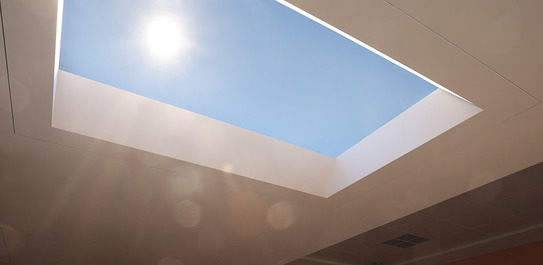
Imagine: it is 4pm, already dark in the middle of winter. You walk into a room and see a column of warm yellow light shining from an aperture on the ceiling. As you approach, you can see the pure blue of a summer's day. The sun is shining brightly, bathing the vicinity in light. You move your head back and forth, using parallax to figure out the illusion—how far up is this "sun" mounted?—but the sun follows your head as you move, exactly as if it were one hundred million miles away.
In this class, my aim is to build an artificial skylight that presents the physically-realistic appearance of an infinitely distant sun in a clear summer sky.
To do so involves basically some optical trickery:
- To build a bright illuminator to simulate the sun.
- To build a concentrator to direct the light in one non-diffuse direction.
- To build a parabolic reflector so as to create the illusion that the sun is infinitely far away. (Placing the "sun" near the parabolic focus and hiding it from the viewer will create a mirror image that appears to be infinitely distant.)
- To fabricate a material that will refract white light in the same manner as sunlight reflects in the air, producing a bright sky-blue ambient color and a warm yellow glow around the sun itself. (This requires white nanopowder which is smaller than visible wavelengths of light, e.g. 300nm. In my prelimary tests this first week, I have found a brand of sunscreen containing passable amounts of these nanomaterials.)
- To build a containing chassis which securely elevates the skylight apparatus, holds everything in place, hides some of the trickery from view, and presents a windowframe-like facade.
Part of the inspiration for this project comes from prior work by Coelux, though I intend to take it to another level—in terms of scale, inexpensiveness (I intend to use only readily-available DIY kinds of materials and processes, rather than expensive precise ones in the range of $10k or more), and mobility (I hope to mechanically actuate the rotation of the mirror to create sunsets).
I have some additional ideas for stretch goals, assuming this project works as planned:
- To make the viewing window as large as possible. I have done volume calculations for parabolic mirrors, and I think it would be fun to push the limit on how large such a window could be.
- To enable the parabolic apparatus to rotate, which given the sky-like composite would instantly pave the way for realistically-colored sunsets.
- Alternatively, to build in static multiples, showing different times of day for each.
- To purify the refracting substance, filtering the ~100nm sized nanomaterials from the sunscreen using, for example, the capillary action of a branch from a sap-bearing tree.
- To simulate other atmospheric effects—wind, clouds, sound, smell, variable light levels as a result of simulated cloud cover, variable light levels as a result of a simulated tree canopy.
- To replace the sun with a starfield, e.g. by creating a black sphere with holes surrounding the artificial sun. The trick here is to fabricate sufficiently small stars, within the tolerance of the smoothness of the parabolic reflector, and to avoid light leakage.
1 Prototyping
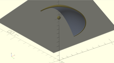
Generating a paraboloid in CAD software is a matter of generating a 2D parabola (by cutting a cone, i.e. conic section) then revolving the parabola about its axis.
The parabolic reflector will actually only need to be half of a paraboloid. For the same reason as a satellite dish, the focus should be on the periphery of the shape so that it can be hidden from view underneath.
//////////////////////////////////////////////////////////////////////////////////////////////
// Paraboloid module for OpenScad
//
// Copyright (C) 2013  Lochner, Juergen
// http://www.thingiverse.com/Ablapo/designs
//
// This program is free software. It is
// licensed under the Attribution - Creative Commons license.
// http://creativecommons.org/licenses/by/3.0/
//////////////////////////////////////////////////////////////////////////////////////////////

module paraboloid (y=10, f=5, rfa=0, fc=1, detail=44){
	// y = height of paraboloid
	// f = focus distance
	// fc : 1 = center paraboloid in focus point(x=0, y=f); 0 = center paraboloid on top (x=0, y=0)
	// rfa = radius of the focus area : 0 = point focus
	// detail = $fn of cone

	hi = (y+2*f)/sqrt(2);								// height and radius of the cone -> alpha = 45° -> sin(45°)=1/sqrt(2)
	x =2*f*sqrt(y/f);									// x  = half size of parabola

   translate([0,0,-f*fc])								// center on focus
	rotate_extrude(convexity = 10,$fn=detail )		// extrude paraboild
	translate([rfa,0,0])								// translate for fokus area
	difference(){
		union(){											// adding square for focal area
			projection(cut = true)																			// reduce from 3D cone to 2D parabola
				translate([0,0,f*2]) rotate([45,0,0])													// rotate cone 45° and translate for cutting
				translate([0,0,-hi/2])cylinder(h= hi, r1=hi, r2=0, center=true, $fn=detail);   	// center cone on tip
			translate([-(rfa+x ),0]) square ([rfa+x , y ]);											// focal area square
		}
		translate([-(2*rfa+x ), -1/2]) square ([rfa+x ,y +1] ); 					// cut of half at rotation center
	}
}


g = 20;

translate([0,0,100])
    union() {
        sphere(4);
intersection() {
    translate([2*g,0,0]) cube(size=[4*g, 8*g, 8*g], center=true);
rotate([0,180,0])  difference() {
 paraboloid (y=2*g,f=g,rfa= 0,fc=1,detail=120);
color([0.7,0.8,1.0]) paraboloid (y=2*g,f=g*0.95,rfa= 0,fc=1,detail=120);

}
}
    % translate([0,0,-g]) cube(size=[180,180,1],center=true);
}
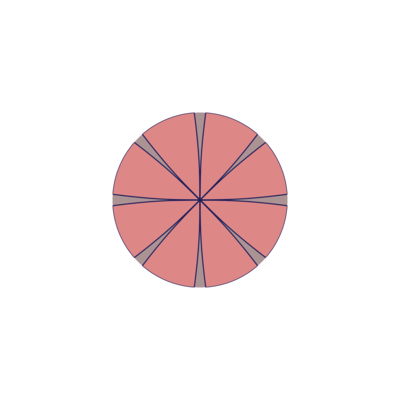
In one incarnation, you could build a parabolic reflector by cutting out a 2D petal-like shape from flexible material (such as Mylar), then joining the edges together to form it into a precise three dimensional shape, then fixing the shape in place somehow.
After figuring out the calculations by hand (integral tables were required), I wrote a Python program to draw the appropriate petal shapes as SVG graphics. The program is parametric, drawing any number of petals and constructing a paraboloid of any dimensions / focus.
from math import sin, cos, sqrt, pi
import svgwrite
from svgwrite import cm, mm
import scipy.integrate as integrate


parabolic_arc_integrand = lambda f: lambda u : sqrt(1 + (u/(2*f))**2)


twopi = 2*pi

def euclidean_length((x,y), (x0,y0)=(0,0)) :
    return sqrt((x-x0)**2 + (y-y0)**2)

def plot_paraboloid(focal_length=1, num_petals = 4, outer_radius=16, epsilon=0.001) :
    integrand = parabolic_arc_integrand(focal_length)
    arc_length = lambda r: integrate.quad(integrand, 0, r)[0]

    # radius_start = 0
    # radius_end = 1

    point = (0.0, 0.0)
    r = 0
    while 1 :
        r += epsilon
        s = arc_length(r)

        angle = pi/num_petals * (1 - r/float(s))

        point = ( r * cos(angle), r * sin(angle))

        if euclidean_length(point) > outer_radius :
            # print ">>> ", point, euclidean_length(point), outer_radius
            return
        yield point


def plot_points(points, filename, width, height, dwg=None) :
    dwg = dwg or svgwrite.Drawing(filename, size=(width,height))

    def chart((x,y)) :
        u = 70*x + width/2
        v = 70*-y + height/2
        return (u, v)

    max_radius = max(map(lambda p : euclidean_length(chart(p), chart((0,0))), points))

    circle = dwg.add(dwg.circle(center=chart((0,0)), r=max_radius, fill="#ccc"))
    curve = dwg.add(dwg.polyline(map(chart, points), stroke='blue', stroke_width=4, fill='none'))
    print map(chart, points)


    # hlines = dwg.add(dwg.g(id='hlines', stroke='green'))
    # for y in range(20):
    #     hlines.add(dwg.line(start=(2*cm, (2+y)*cm), end=(18*cm, (2+y)*cm)))

    return dwg


def create_rose(focal_length, num_petals, outer_radius, filename) :
    width = height = 2560
    def chart((x,y)) :
        u = 70*x + width/2
        v = 70*-y + height/2
        return (u, v)
    def rotate(angle, reflect=False) :
        r = -1 if reflect else 1
        return lambda ((x,y)) : (x*cos(angle) + r*y*sin(angle), x*sin(angle) - r*y*cos(angle))

    dwg = svgwrite.Drawing(filename, size=(width,height))
    points = [p for p in plot_paraboloid(focal_length, num_petals, outer_radius)]
    max_radius = max(map(lambda p : euclidean_length(chart(p), chart((0,0))), points))

    circle = dwg.add(dwg.circle(center=chart((0,0)), r=max_radius, fill="#ccc"))

    for i in range(num_petals) :
        for reflect in (True, False) :
            curve = dwg.add(dwg.polyline(map(chart, map(rotate(i*twopi/num_petals, reflect), points)), stroke='#222', stroke_width=4, fill='none'))

    dwg.save()

create_rose(4, 8, 10, "output.svg")
2 Weekly progress updates
Nanomaterials. I have tested out varying brands of sunscreen as possible sources of small white nanoparticles whose size is smaller than visible light. Mineral-based no-show sunscreens contain oxides of titanium and zinc at just the right size. Next I might experiment with a filtration process.
Mirror coordinates. Previous incarnations (e.g. by Coelux) have featured an empty sky. But the space behind the mirror provides an entire virtual 3D space. Can we fill it with objects like trees and so on? After some involved geometric calculations, I've found a function for un-distorting mirror images. By precisely printing strange anti-distorted shapes, I can populate the virtual mirror world with un-distorted shapes such as trees, columns, mountains, and perhaps even clouds.
Derivation: Given a vertical parabola focused on the origin, let's pick a point in virtual space (behind the mirror). We can identify the point using its x-coordinate and the angle α between the point, the focus, and the x-axis. It turns out that there's exactly one point in real space corresponding to that imaginary point. Its coordinates are:
$$\widehat{x} = \frac{1+\sin{\alpha}}{\cos{\alpha}}$$ $$\widehat{\alpha} = \arctan{\frac{1/4 x^2 - f}{x}}$$
By applying this transformation to a shape we wish to see behind the mirror, we get a distorted shape that we can place in front of the mirror whose reflection is that desired shape. Amazingly, the reflected shape will be 3D, so that it will look correct from any angle. This theoretical result may be limited in practical effect for two main reasons: first, it depends strongly on the smoothness and precision of the parabolic mirror; second, the distorted shapes may sometimes intrude between the viewer and the mirror, demystifying the illusion.
Star mesh. I've been experimenting with different methods of making a starfield appear above the mirror. Part of the design constraint is that the stars must be very very fine—true stars appear like pinpoints, and because these stars must be placed near the focus, they will tend to be magnified a great deal. I hope to find a process that allows me to create stars finely even if I can't control their positions.
I first wanted to see how finely 3D printing can create objects. The answer is not very, in practice. I created a design parameters board consisting of holes of precisely varying diameter along one dimension, and precisely varying spacing along another. But due to the temperamental nature of the filament, the quality was variable: some of the large holes were filled with gunk, even though some of the smaller holes were clear. And there were loose strands of filament that had snagged on the shape as well. I think this process is not quite reliable, although maybe making several interlocking meshes will work.
I intend to try other processes, such as acid-burning or poking away material in a stochastic way. Although it would be neat to recreate the zodiac accurately…
Patents. I have looked up various patents for prior work (e.g. by Coelux) and am endeavoring to understand how they work. Many of them seem deliberately obfuscated. Updates as progress warrants.
Design of the mirror. Having surveyed the Internet and asked around, I have decided that a good first attempt at a making a curved mirror would be to use the inflation procedure as described here: https://www.youtube.com/watch?v=8CLRTa_ocmo . It looks really smooth relative to other procedures I was considering (e.g. flat flower-shaped material that folds up into a parabola), and gives a good target for the subjects learned in future weeks.
The result is not technically a parabolic mirror; I believe that theoretically it's a revolved catenary curve (hyperbolic cosine) just like the meniscus between two fluids.
Continuing reading on patents. A lot of the strategy involves (a) focusing the light so that it does not disperse too widely, weakening the difference between yellow sun and blue sky, and (b) uniformly diffusing the ambient light so that there are no patches of light and dark sky. In keeping with my self-imposed design criteria, I am looking at ways of achieving these effects inexpensively, without relying on pre-made diffusers and so on.
Obtained RGBW leds from the Internet, and working on assembling a lighting rig (pictures to follow, once I can program them). The main design criterion is that they be sufficiently bright, which may require external cooling in the extreme case. I think it could be entirely feasible to make my own heat sink out of aluminum on the OtherMill. Another design criterion is that I can control them based on color temperature, in software. This requires assembling a realistic spectrum from warm (low temp) to cool (high temp) color in software.
The mirror container. For wildcard week, I intend to build a composite structure that I can use to inflate a mylar sheet into an almost-paraboloid. The first part of that process involves designing a sealed container for mounting the mylar. I'm taking inspiration from molding and casting week in my design, and hope to study composites in particular soon.
I am planning both this week and next week to design and build a prototype motor that could effectively rotate a mirror along a single axis. It may be much smaller than the final product, just so I can get familiar with motor design, pwm, etc. but it should be a useful prototype.