 Ordered tube amp kit
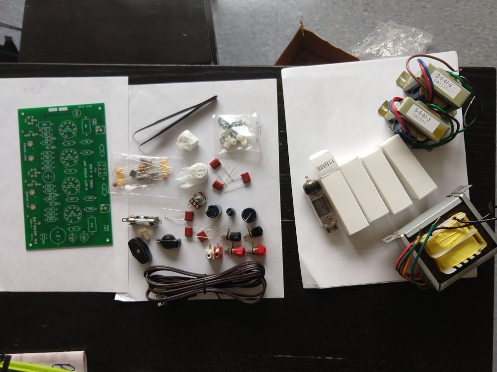
 For the tube amp, my initial thought was to design and build it completely myself. However, the following factors contributed to my use of the existing kit solution (AES kit )
I have ordered the kit and after a half a day of work, assembled everything (and spotted a few design errors, like an improper grounding of the pot)
Ordered tube amp kit
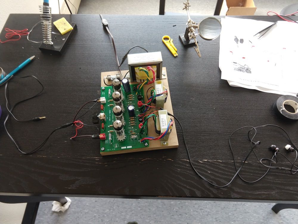 Assembled kit
Now, one might think that the tube is ready and it is over. Unfortunately, though it does amplify the signal, the amount of 60 Hz hum and AM-radio noise that this tool emits is almost unbearable. I need to fix that.
I have spotted a few general ideas circuling over the internet that might contribute to the hum in tube amps.
After investigating a topic, I almost gave up at some point. But then it occured to me that we all live in the areas with a huge amount of RF and 60 Hz radiation present pretty much everywhere, coming from our microwaves, fridges, outlets, cellular networks, etc. What if I shield the entire amp in a metal enclosure, i.e. introduce a chassis
In addition to insulating my amp from the outer world, the grounding will serve a critical purpose: it will make this device safe to operate and prevent me from any possible electrocutions. The current design of the kit is horrible in terms of safety: the high voltages are floating, the device is not grounded and all the parts are exposed.
Now the problem of grounding is that this represents a whole new world, in which one (properly trained) individual with some effort probably can make the device being save. However, getting rid of the newly introduced noise due a number of probable ground loops is the problem that is very far from easy to resolve. Hence, in a way, I need to not only shield the device from the outer world, but also shield it from itself.
A lot has been written on the topic of grounding, where the discussions of the proper relations between the power ground, safety ground and signal ground are described. A good read, related to grounding of tube amps can be found here.
In short, I need to make sure that my signal inputs, signal outputs, volume pot, power ground and chassis (and the future DC ground for the DAC microcontroller) should be connected only in one point, ideally on the chassis, and ideally close either to the input signal ground or to the power ground.
The assembly process took around 2 days in total due a few tricky moments with the wiring. Note that the thick ground braid that connects the ground pin from the outlet to the center o the enclosure is also installed (not shown on the pictures below). This step is critical for ensuring the safe use of the device.
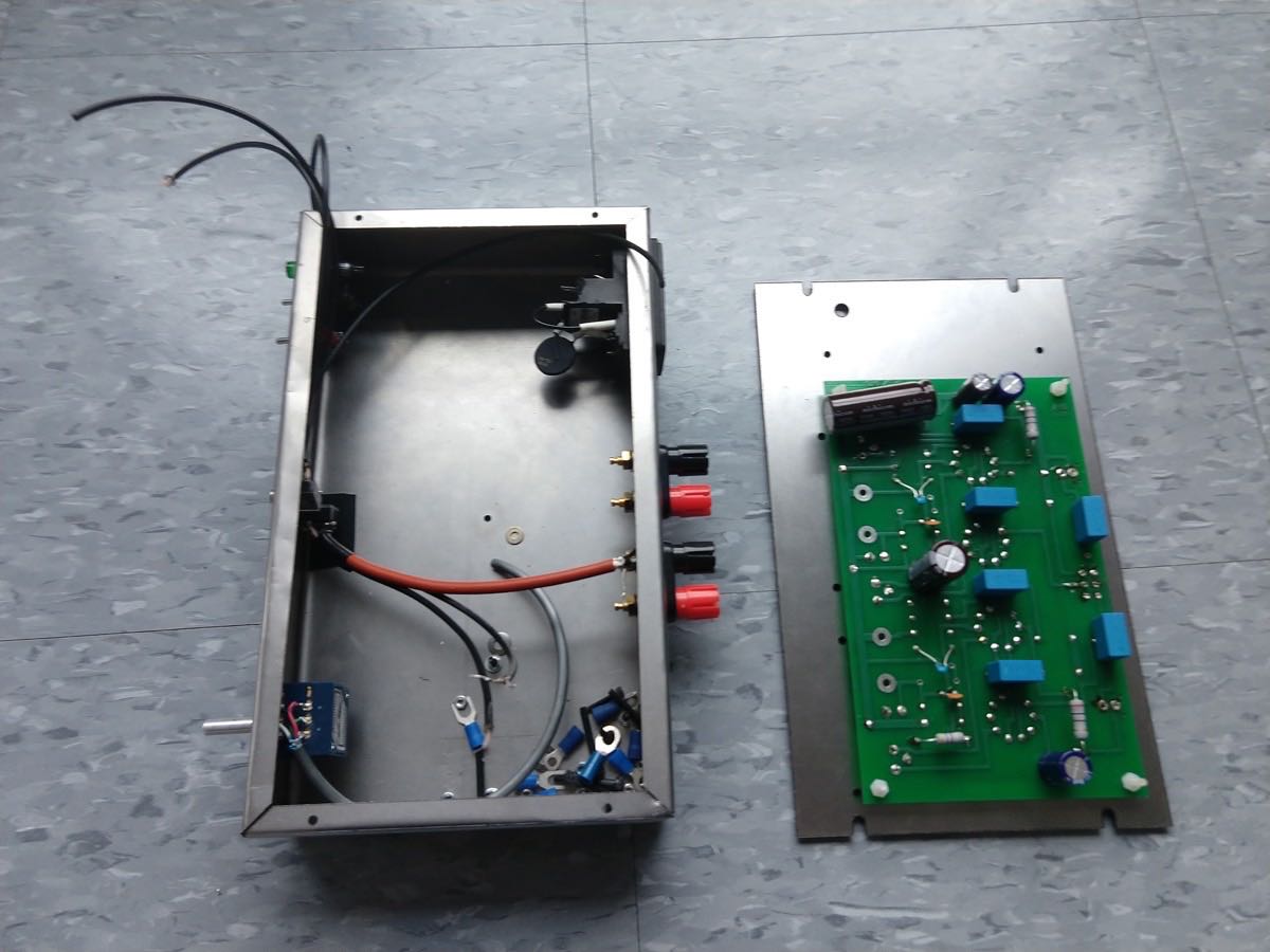 Starting to stuff the enclosure
After all the switches and indicators with the wirings were finished, I proceeded with putting the transformers inside of their respective enclosures, which I then connected to the lid. I also put the plastic grommets into the cut holes in order to make sure a good wear-free insulation for high voltage wires:
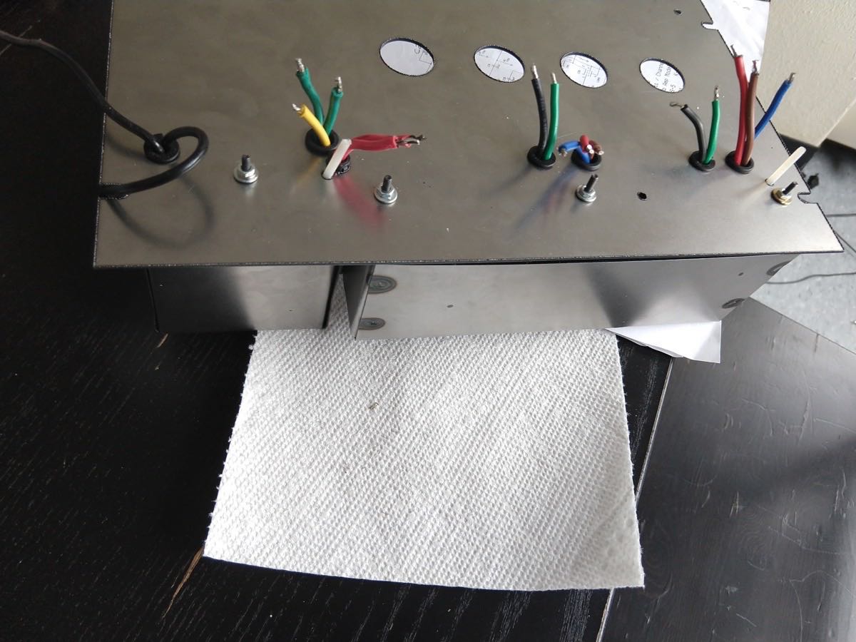 The wiring is ready
After juggling with all the wires and connecting all the input/output/DAC board inputs, I proceeded with lighting up my amp:
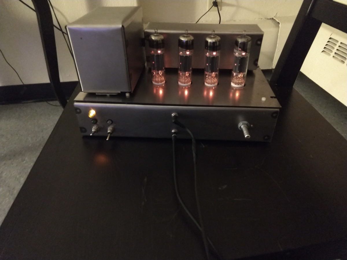 The tube amp is ready
Note that for connecting jacks, I used the mechanical switch option (see an example and the related discussion here). A cool feature of such female connectors/switches is that once the headphone jack male connector is in, the audio signal from the amplifier no longer travels to the speakers. Nowadays, everyone uses the electrical switches/female connector, but I hesistated to introduce such an unnecessary complexity.
Of course, I really wanted to test the performance of this amp even before waiting for the recommended 40-50 hours run (during which the tubes will reach their optimal performance). To perform the audio tests, I used the signal generator, a scope and FFT network analyzer with the passive 8Ohm resistors connected to the output of the amplifier.
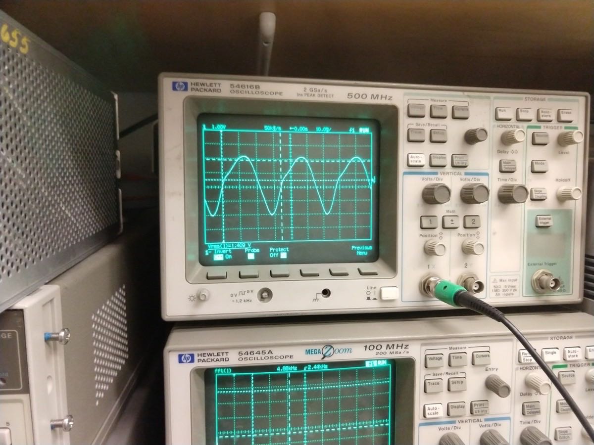 Low-frequency 3dB point is 30Hz
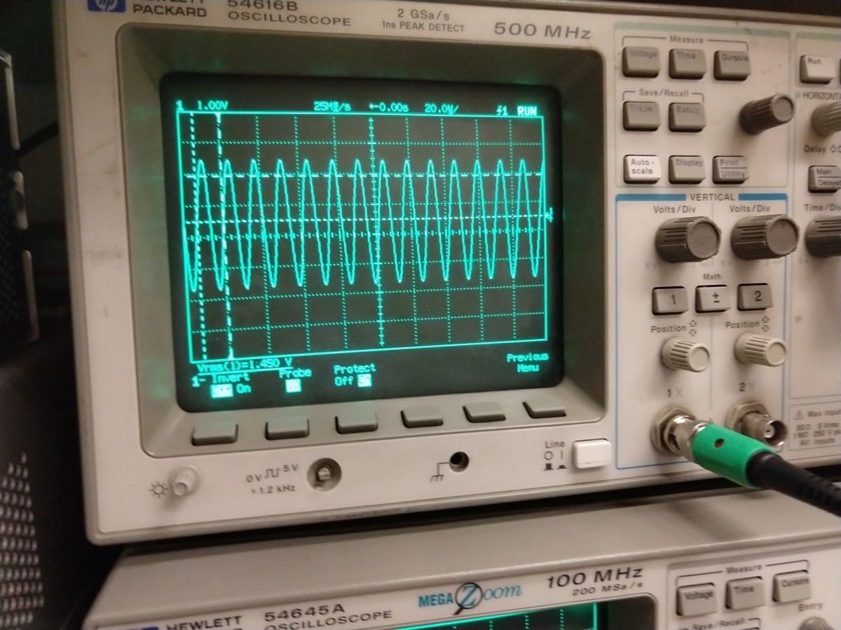 High-frequency 3dB point is 70kHz
I was very surprized with the frequency range of the amplifier, in particular with the 70 kHz high frequency point. The 30Hz low frequency point was more than sufficient for me, since my speakers will definitely be worse than that.
Finally, the total harmonic distortion winded up being slightly worse than I expected, which might be partially due the noise and hum present in the audio channels. However, this seemed inaudible to me.
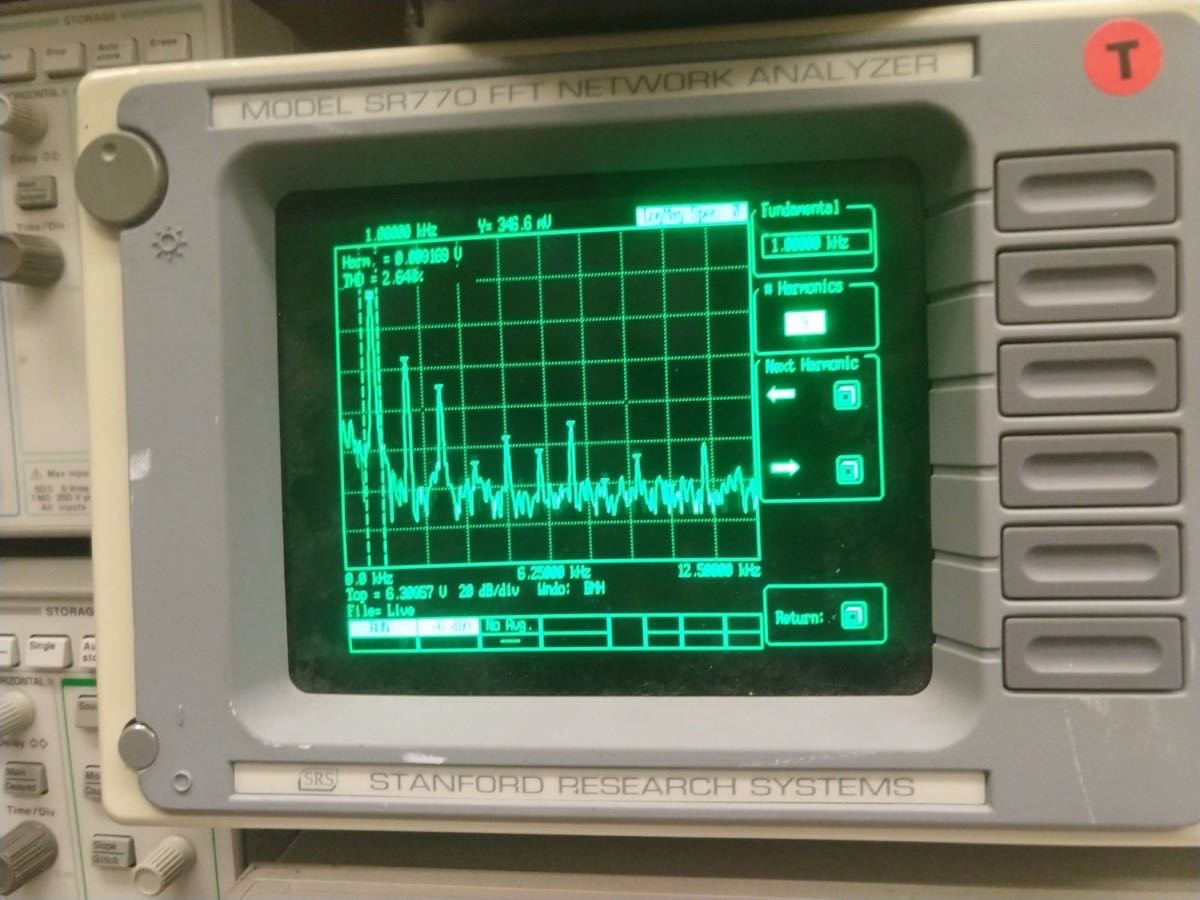 Total harmonic distortion at 1W is 2.64% (more than the claimed smaller than 1%)