 Drawing schematic
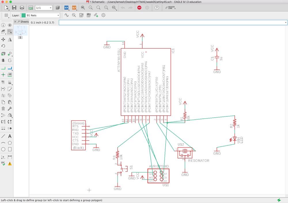
 This week, we turn to the designing of circuit layout. Our task is to redraw the echo hello-world board (based on the ATtiny44 controller) with a few modifications, followed by making and testing it.
For designing the PCB, I chose Eagle. The design itself consisted of three parts: drawing the schematic, arranging parts, and routing. In my design, I have also introduced a blue LED and a switch with current limiting resistors, which were connected to pins PA7 and PB2 respectively
Drawing schematic
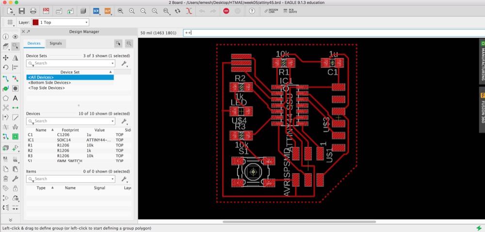 Parts arrangement and routing
Afterwards, I converted the design files to the png for the traces and outline, which after the necessary step of scaling the resolution by a factor of two, were ready to be feeded into the mods software:
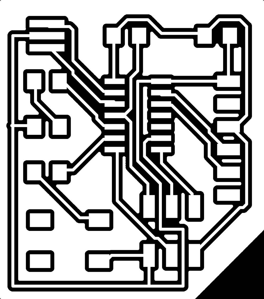 Traces
 Outline
One can see that I have also introduced a ground plane. At the moment, it serves no purpose other than accelerating the milling process. However, in my future designs, I would like to use this feature as an easy access to the ground voltage (if properly done, the voltage on the ground plane will be very close to the promised ground reference value due to the dimensions, unlike in the case of a thin GND trace)
After milling the board, I have carefully removed all the residues under a microscope. Then, I have stuffed the board, with the following outcome:
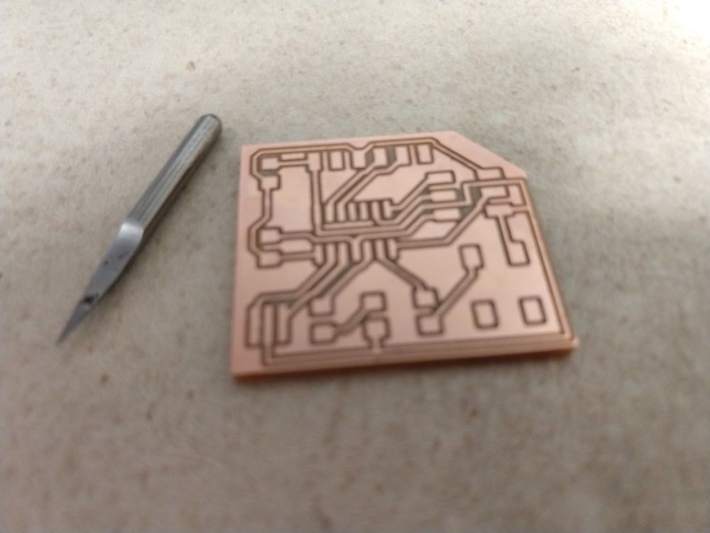 Milled board + fine work
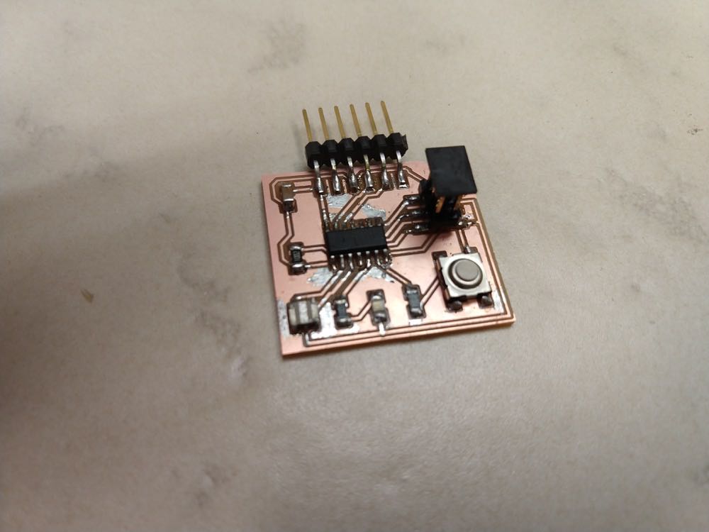 Ready board
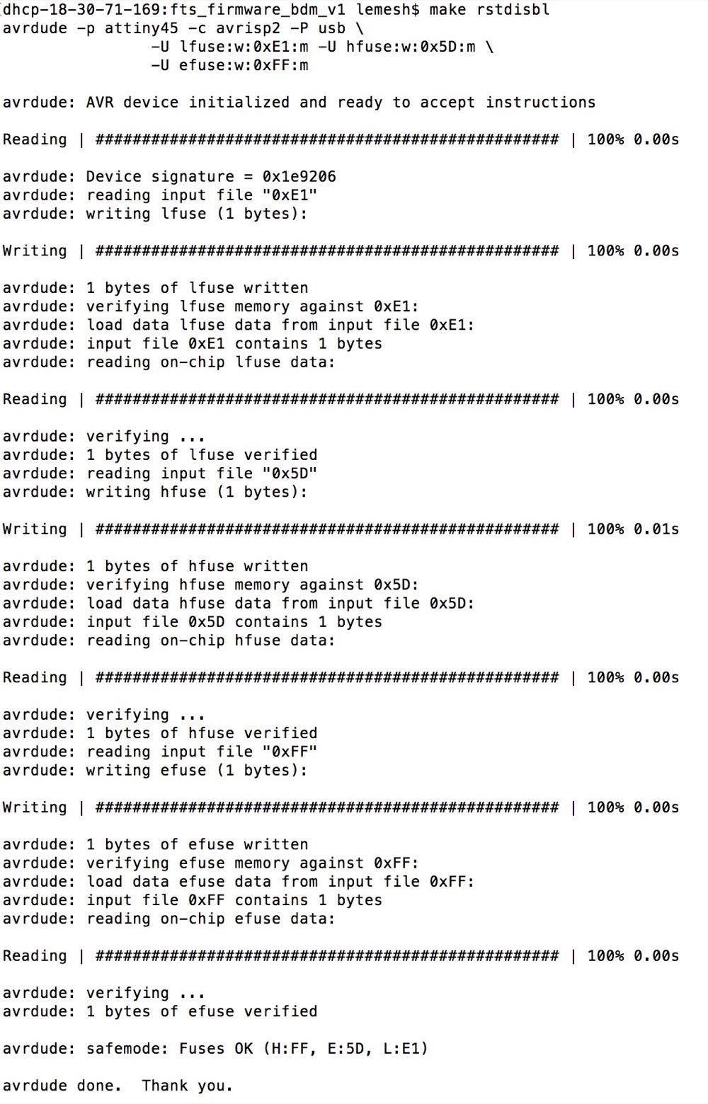
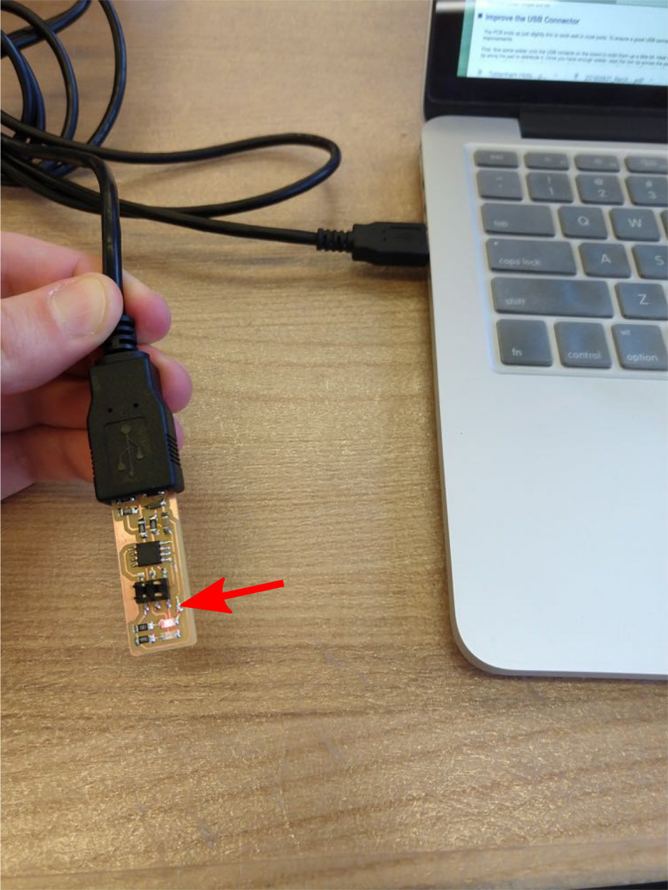
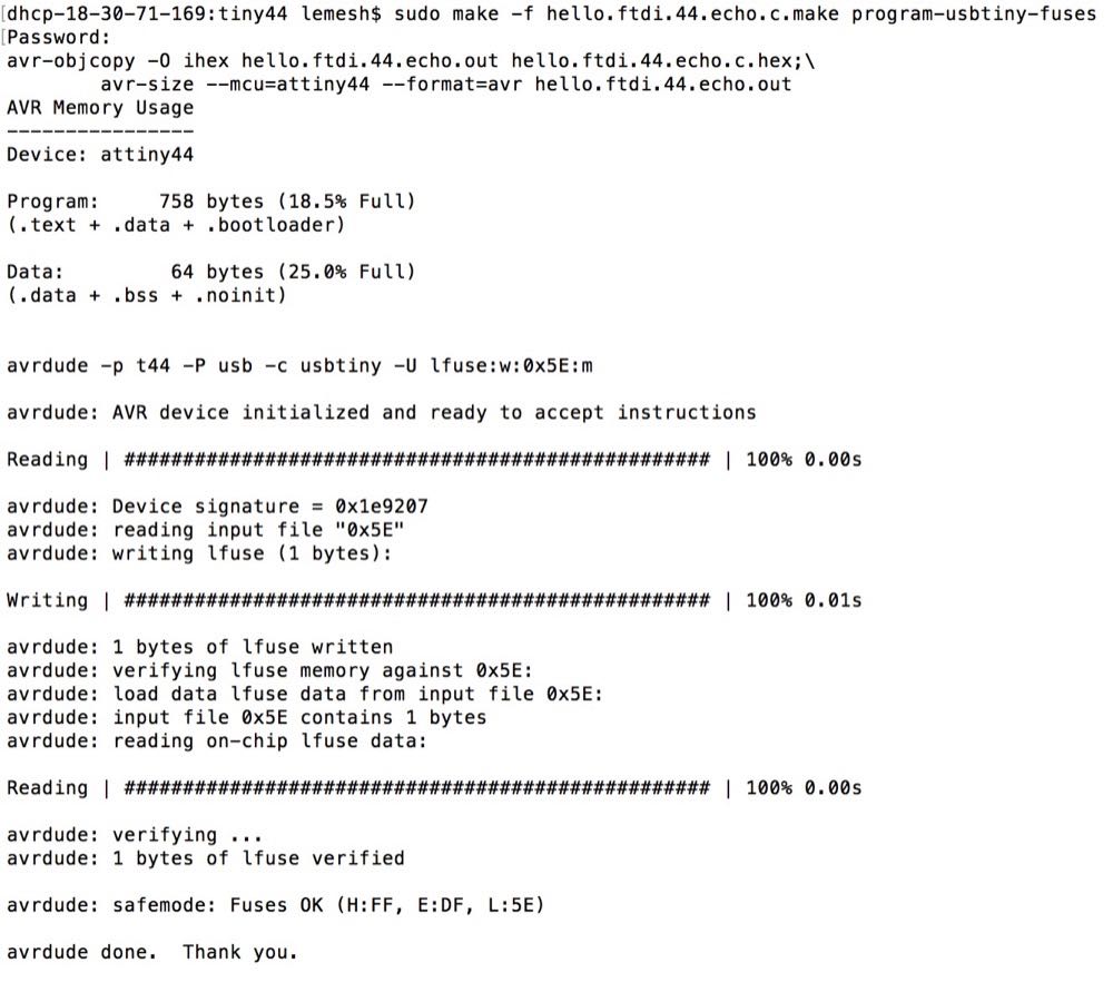
In Week3 assignment, I have built the DIY programmer (and programmed it with a common avrisp2 programmer). To finish it, I needed to turn the ATtiny45's reset pin into a GPIO pin, which can be accomplished with a simple "make rstdisbl" command. Afterwards, I blew the reset fuse (denoted with an arrow below)
 Disabling reprogramming
 Blowing the reset fuse
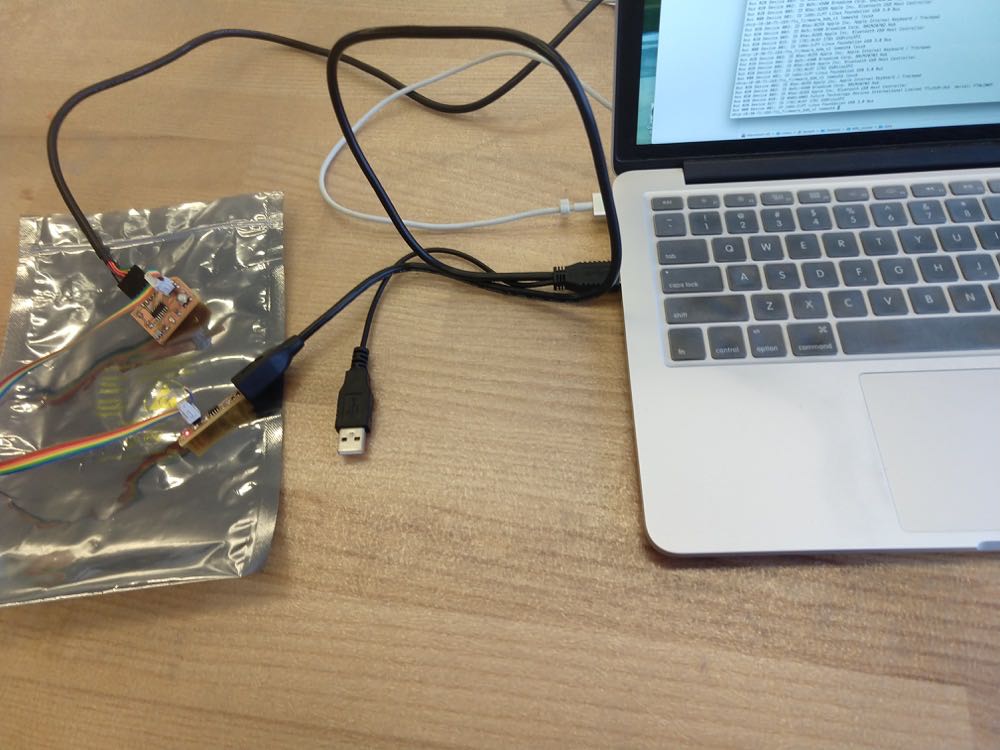
Now is an interesting part: I connect a DIY programmer with a DIY hello world board (and also connect it to a computer with the FTDI serial-to-USB cable).
 Rhino modelling
I then programmed the latter board with the code whose function is to return whatever one presses on a keyborad.
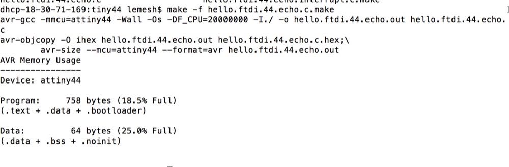
 Programming echo hello-world board

Once programming is done, one can find both the programmer and the board in the external devices of my computer. Finally, I disconnted the programmer, leaving only the ATtiny44 board. As one can find below, the Hello world program works out great!
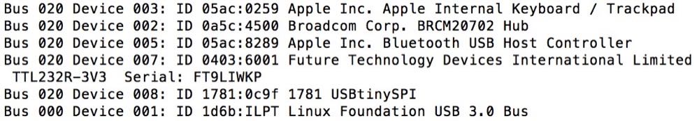 Found devices
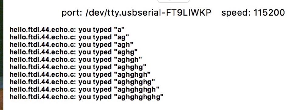 Hello world program
It took a few seconds of a delay to wait for the output display after pressing on the keyboard.
Just as a quick reality check, I have decided to test what happens at the FTDI interface. When no button is pressed (G, CTS, VCC, TX, RX, RTS) signals are measured as (0.0, 4.0, 5.0, 4.0, 4.6, 0.0) Volts.
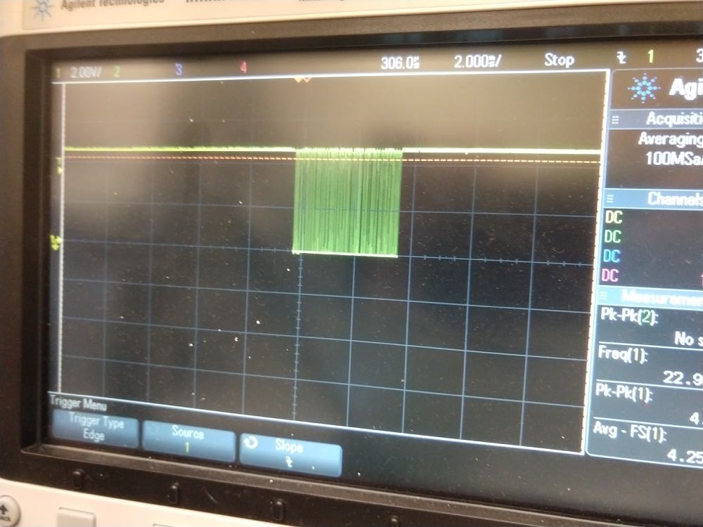
The pins of interest are TX and RX. After the button is pressed, one can find the following changes in voltages at those terminals, which last for ~5 ms:
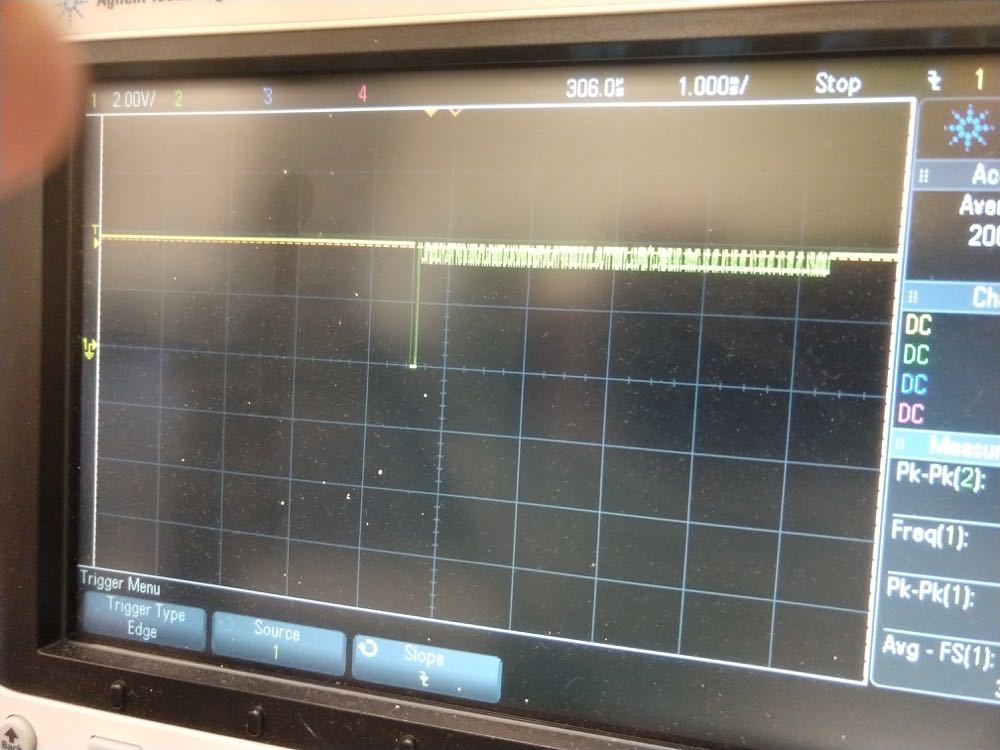 TX signal
 TX signal (fine)
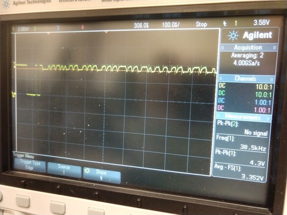
The TX signal drops to zero for ~100 ms followed by a set of small ~0.6Vpp oscillations
 RX signal
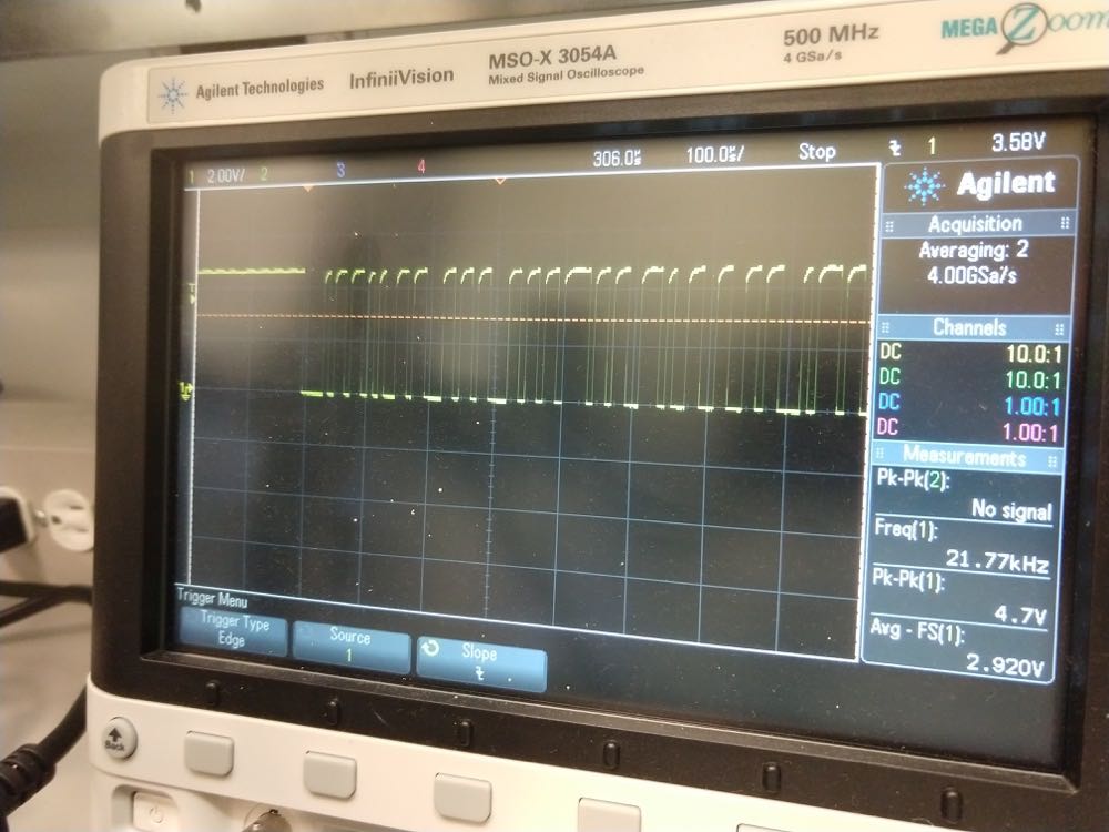 RX signal (fine)
As for the RX signal, it oscillates between 4.6 and 0.0 V for ~4ms.