Final Project, final push.
Alright so it's the last few days before the project presentation and here's a checklist of what I have ready and what I need to get done:
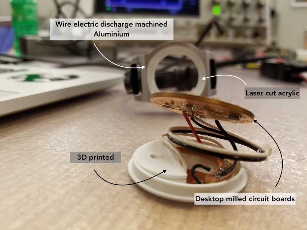
Design the watch casing - done on Fusion360
Cut out watch casing - done during wildcard week using the wire EDM
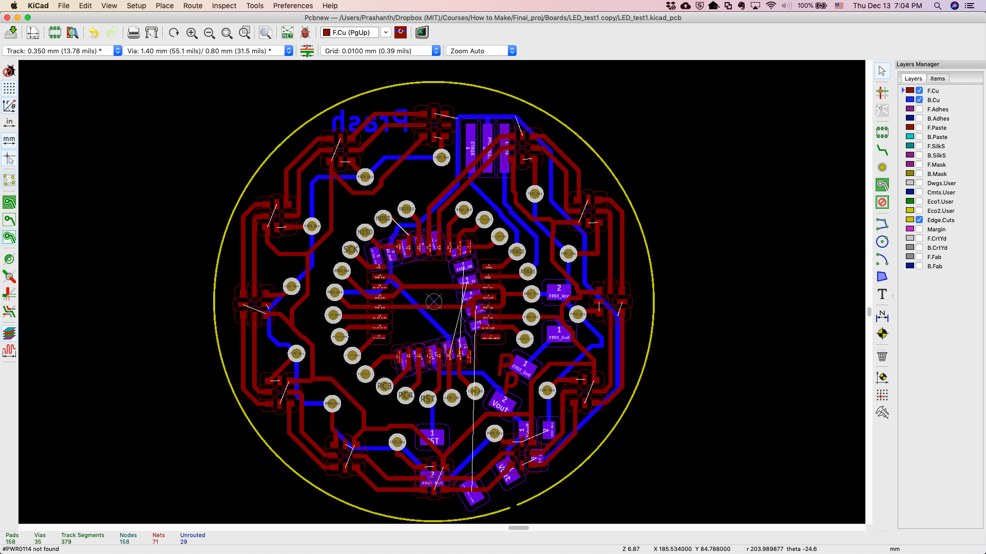
Design PCB with all the electronics that has the following
MCU - ATMega328P
Bluetooth module - RN4871
12 APA102 - 2020 LEDs
Required resistors/ capacitors etc
Touch - step response system - NEED TO ADD RESISTORS and need to [CODE][#step-response-code]
Think about other things to add?
Things to keep in mind
Seems like the BLE module will cover up the Rx Tx of the touch input. So options include:
- Use the Blue_led and Switch lead as the two Tx pins.
- Route the Tx wires from the top surface - Meh probably won't look good. Besides doesn't seem like it really matters which GPIO pins are used for the Tx lines.
Remember to solder a wire connection for the BLE reset!
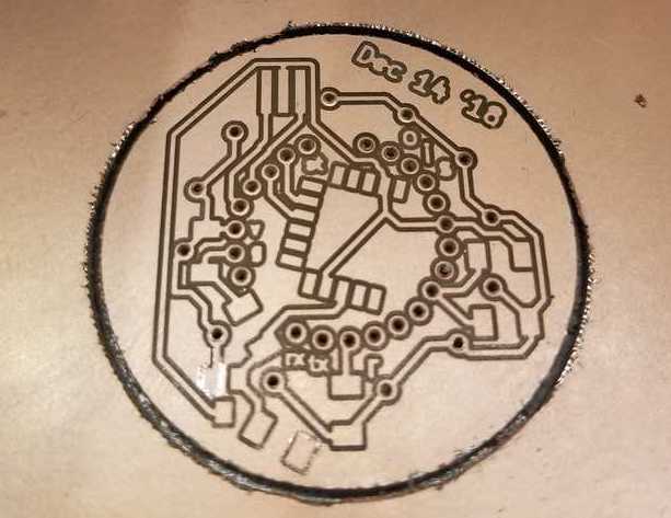
Legend on back copper layer:
- s = SCK
- i = MISO
- o = MOSI
- g = GND
- v = Vcc
- r = reset
- rx = ATmega's receive
- tx = ATmega's transmit
Status of Board as of Friday!
Producing the circuit board
Here is a quick showcase of the steps taken to produce the final circuit board:
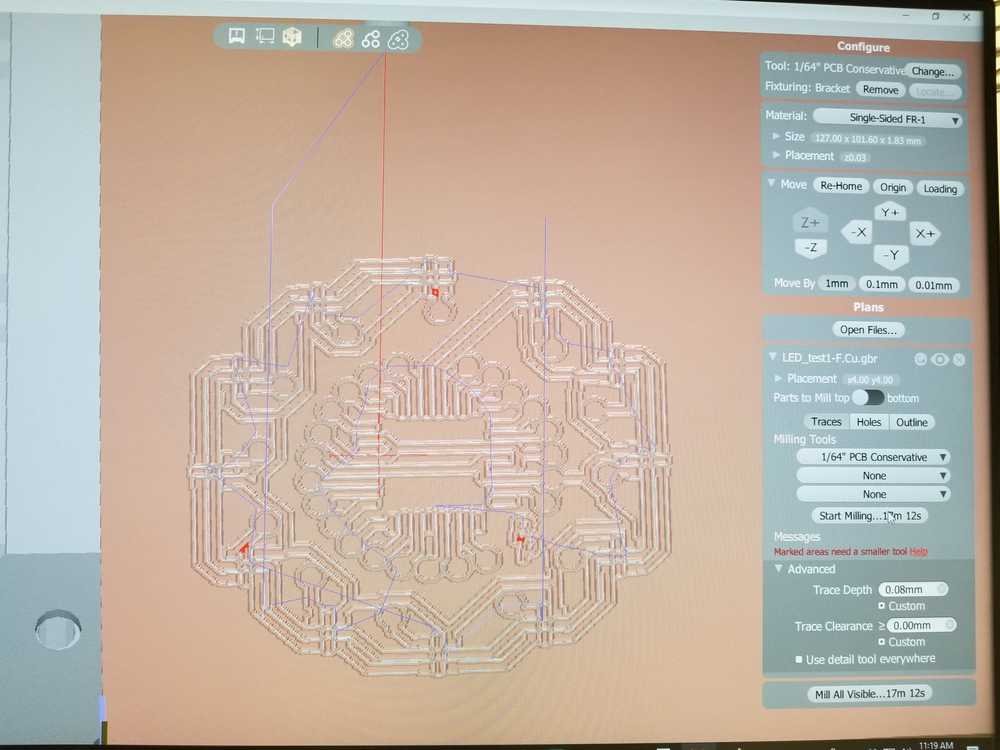
Here is the Gerber file loaded onto the Bantam software for cutting on the Othermill.
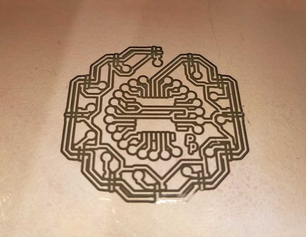
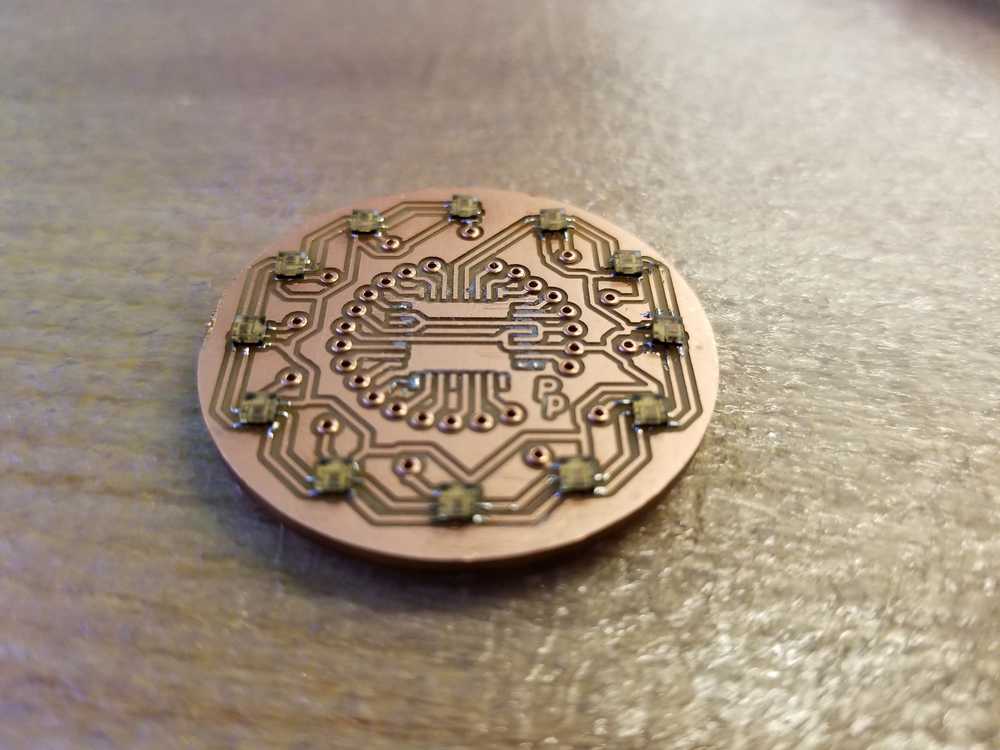
Here is the top traces cut out
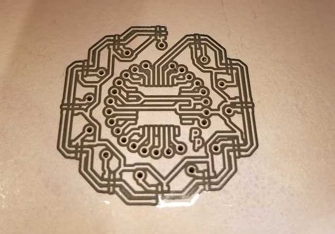
and then the holes drilled out. You can see that there is a small portion where the mill did not completely cut through, this needs to be corrected later
and finally the reverse side cut.
Soldering on the LEDs
The LEDs that I'm using APA102-2020 have Tiny footprints. So based on previous iterations, I decided to carefully try making a stencil using the vinyl cutter.
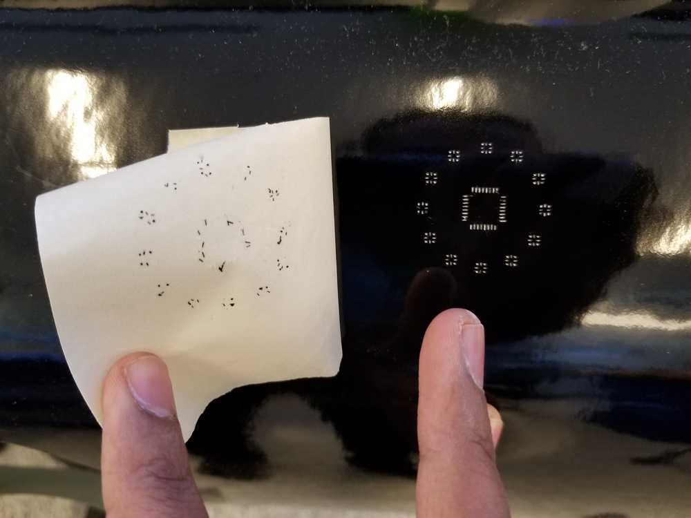
and then carefully placed the stencil on the top surface of the board and applied solder paste to get the follwoing result:
Step Response Code
Basically it's saving two 16-bit values up and down that correspond to when the MCU sets the Tx line high and low respectively.
Dual sensors
Ideally I would like to have two touch sensors - one on the left and one on the right of the watch dial. However, as I'm designing the watch face, I'm quickly running out of space and pads. So what I want to try is to use a single Rx line and two Tx lines - one for either side. Then, in code I can turn on the transmit lines sequentially and then sample the Rx lines. Hopefully, this works...
Here is the main part of the Tx-Rx example code form the class website:
xxxxxxxxxxwhile (1) { // // accumulate // up = 0; down = 0; for (count = 0; count < nloop; ++count) { // // settle, charge // settle_delay(); set(transmit_port, transmit_pin); // // initiate conversion // ADCSRA |= (1 << ADSC); // // wait for completion // while (ADCSRA & (1 << ADSC)) ; // // save result // up += ADC; // // settle, discharge // settle_delay(); clear(transmit_port, transmit_pin); // // initiate conversion // ADCSRA |= (1 << ADSC); // // wait for completion // while (ADCSRA & (1 << ADSC)) ; // // save result // down += ADC; }Issues encountered while manufacturing the electronics
- Despite having the rivets, some connections are very good. They need to be bolstered with solder .
- Using external wires as connectors doesn't seem to be super ideal. Probably need to solder them on to make the connections relailable.
Continuous testing to catch problems earlier and establish minimal functionality
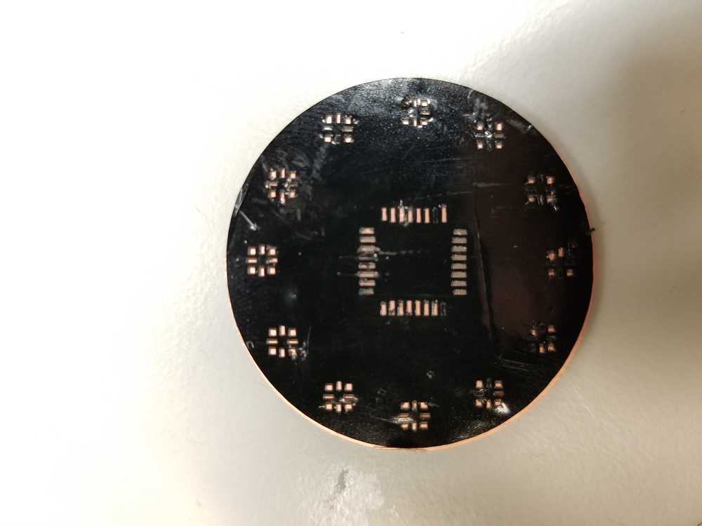
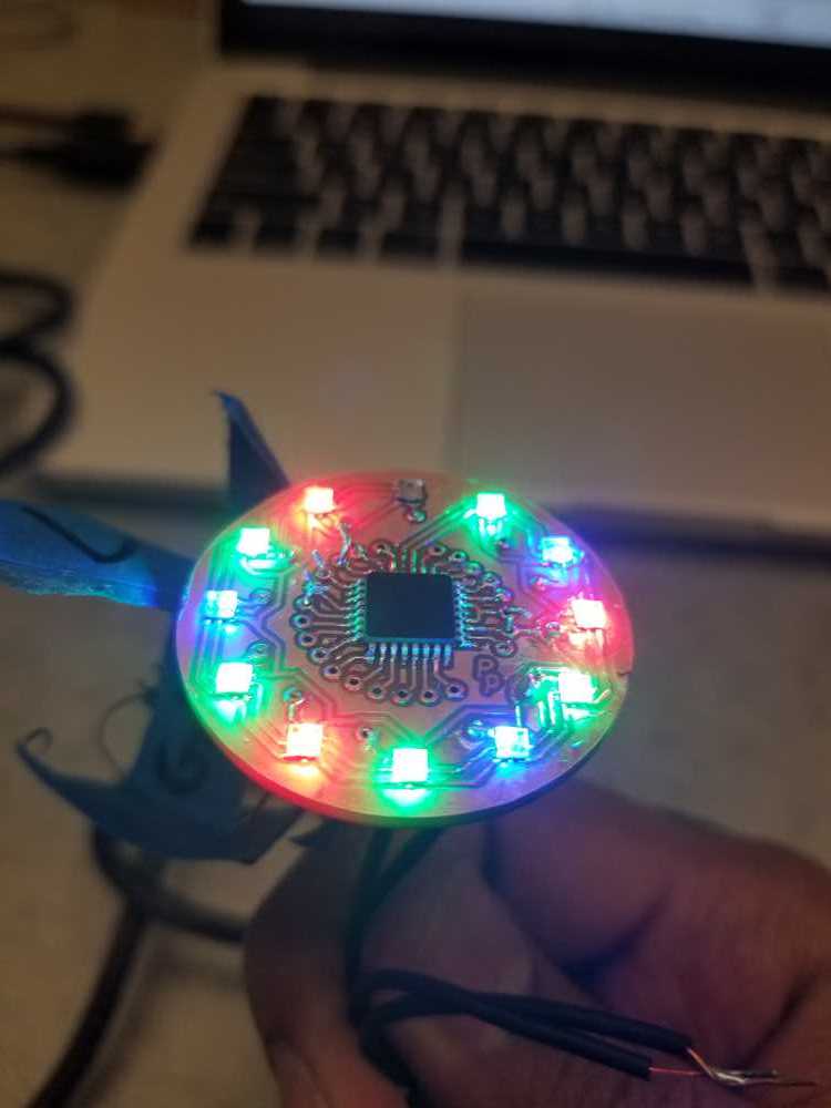
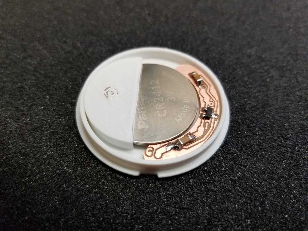
Here is a picture of what the board looks like with just the rivets and LEDs. It wasn't very clear to me when I did this but turns out some of the rivets didn't really make very good connections. Luckily in the workflow I had planned, I wanted to test connectivity at this stage before proceeding with populating all the other components.
Doing so revealed that some of these connections couldn't be salvaged just by using solder to bridge gaps but required more serious intervention...
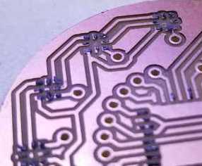
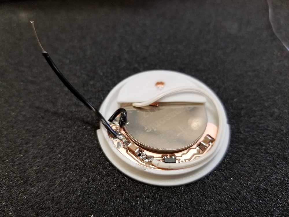
It kinda broke my heart that I had to have these jumper wires to salvage the situation but with the time crunch I had no choice. A saving grace is that my intended plan for the watch face involved frosting the outer circumference of the acrylic layer so as to diffuse and soften the LED glow, which should, in theory cover up the jumper wire on the front face.
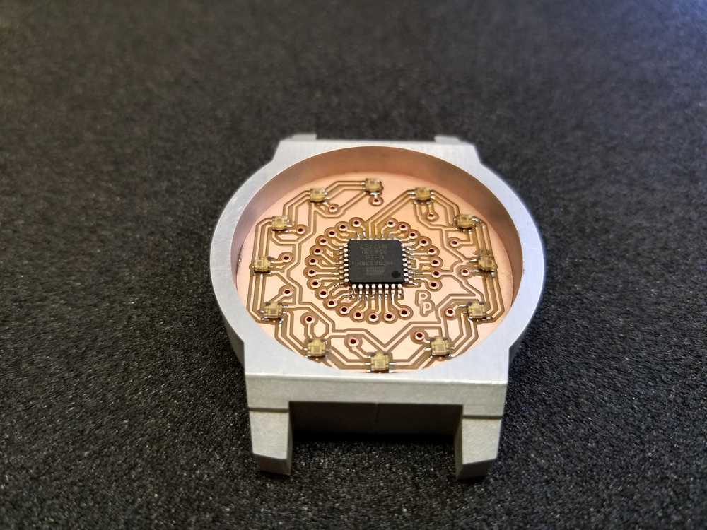
Design detail of the ATMega328P
Here are some details about the pin connections for the main board
Pin connections
"LED clock" = PB0
"LED data" = PB1
"Blue LED" = PD7
"toBLE"= PD6
"frmBLE"=PD5
"Switch"=PB2
"SensorRx"=PC1
Test code
Here is the sample code I used to test the LEDs. "Test" here refers to testing the minimal functionality of the LEDs - do they all turn on. Turns out soldering these tiny LEDs with the reflow method takes some practice... I seem to almost always get it right the second time around.
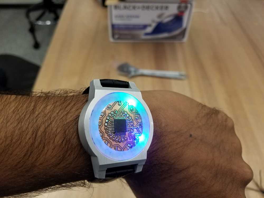
xxxxxxxxxx// To address APA102s,// The data consists of:// A start frame of 32 '0' bits. (4 bytes of '0')// A 32-bit frame for each LED, specifying the brightness and colour.// An end frame of 32 '1' bits.// The 32-bit frame for each LED consists of:// Three '1' bits.// Five bits specifying the brightness, MSB first.// Eight bits specifying the blue component, MSB first.// Eight bits specifying the green component, MSB first.// Eight bits specifying the red component, MSB first.// Port Assignments// Display buffer - sets the brightness and colour of the 4 RGB LEDs// First [LEDs] is # of LEDs, second [4] is for R,G,B, and Brightnessuint8_t Display[LEDs][4];// Software SPI **********************************************void Write (uint8_t c) { int i=0x80; //0x80=0b10000000 while (i) { if (!(c & i)) PORTB &= ~(1<<PB1); // set Data low else PORTB |= (1<<PB1); // set Data high PORTB |= 1<<PB0; // set Clk high i = i>>1; nop(); nop(); PORTB &= ~(1<<PB0); // set Clk low }}void ClearBuffer () { for (int d=0; d<LEDs; d++) { for (int c=0; c<4; c++) Display[d][c] = 0; }}void UpdateDisplay () { for (int d=0; d<4; d++) Write(0); // Start frame for (int d=0; d<LEDs; d++) { Write(Display[d][0] | 0xE0); // Brightness 0-31// 0xE0 = 11100000 which complies with the 3 '1's for the start bit Write(Display[d][1]); // Blue Write(Display[d][2]); // Green Write(Display[d][3]); // Red } Write(0xFF); // End frame Write(0xFF); // End frame Write(0xFF); // End frame Write(0xFF); // End frame}void AllRed (uint8_t brightness) { for (int d=0; d<LEDs; d++) { Display[d][0]=brightness; Display[d][1]=0; Display[d][2]=0; Display[d][3]=255; UpdateDisplay(); }}void AllBlue (uint8_t brightness) { for (int d=0; d<LEDs; d++) { Display[d][0]=brightness; Display[d][1]=255; Display[d][2]=0; Display[d][3]=0; UpdateDisplay(); }}void AllGreen (uint8_t brightness) { for (int d=0; d<LEDs; d++) { Display[d][0]=brightness; Display[d][1]=0; Display[d][2]=255; Display[d][3]=0; UpdateDisplay(); }}void Sequence () { for (int d=0; d<LEDs; d++) { Display[d][0]=brightness; Display[d][1]=255; Display[d][2]=0; Display[d][3]=0; UpdateDisplay(); _delay_ms(100); ClearBuffer(); }} }int main(void) { // // main function. // // Set clock divider to /1 CLKPR = (1 << CLKPCE); CLKPR = (0 << CLKPS3) | (0 << CLKPS2) | (0 << CLKPS1) | (0 << CLKPS0); // // initialize pins output(DDRB,(1<<PB0)); output(DDRB,(1<<PB1)); // main loop while (1) { Sequence(); //cycle through LEDs AllRed(10); _delay_ms(200); AllGreen(12); _delay_ms(200); AllBlue(15); _delay_ms(200); } By the time we had to end for the day I had this going -
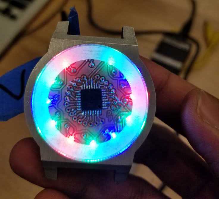
Not bad eh?
Looks a lot like the Arc reactor from the Iron Man franchise.
Some notes on Physical space
| Total depth available after installing Acrylic cover | 8.12 mm |
| Thickness of PCB board | 1.84 mm |
| Thickness of board with components | 4.4 mm |
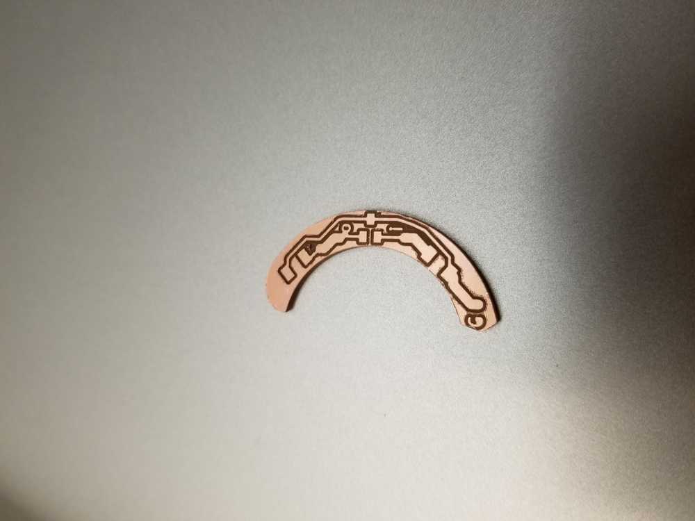
If I want to fit another PCB in the battery case it needs to be crescent shpaed between 24.55 mm and 33.05 mm diameters.
Timers and Interrupts
Alright, now after all the battle scars that my board has endured (including a microcontroller replacement...) it is time to tell time.
ATMega328P has 16 bit timer/counters so the maximum value that these can count to are (subtract one cause they all count from 0).
Since I have a 20 MHz Crystal hooked up to the board and I have the system clock set to run based on the external clock, that's going to count at 20MHz... which is very fast if you want to count to 1 second. So we want to use a prescaler and count at say of the system frequency. This prescaler is set in the TCCR1B Timer/Counter 1 Control Register B.
So that will mean the count frequency can at the slowest be 20MHz/256 =78.125 kHz. This implies that the time for each tick is s s.
Also since the counting frequency is 78125 kHz we need to count up to 78125 for a 1 second interval. Since that won't be possible with our 16 bit register. So we need to split this up to say of a second. In of a second, at a frequency of 78.125 kHz, we have 15,625 ticks. Since all our counters count from 0, that means we will count till 15,624. This value is now possible in our 16 bit register.
So once the counter reaches this value we need to throw an interrupt.
The follwoing bit of code does that, and some more. Bascially the ISR bit of the code handles the interrupt. (ISR = interrupt service routine).
xxxxxxxxxx volatile int fifth; volatile int sec; volatile int min; volatile int hr; ISR (TIMER1_COMPA_vect) // Timer1 ISR { fifth++; // temporarily set the value of fifth to =1 so that it speeds up "time" if (fifth == 1) { sec++; fifth =0; } if (sec == 60) { min++; sec=0; } if (min == 60) { hr++; min=0; } if (hr == 12) { hr=0; } }int main (void){ TCCR1A = 0;// set entire TCCR1A register to 0 TCCR1B = 0;// same for TCCR1B TCNT1 = 0;//initialize counter value to 0 OCR1A = 15624; // Based on above calculation // turn on CTC mode TCCR1B |= (1 << WGM12); // Set CS10, CS11 and CS12 bits for 256 prescaler TCCR1B |= (1 << CS12) | (0 << CS11) | (0 << CS11); // enable timer compare interrupt TIMSK1 |= (1 << OCIE1A); sei(); //enables global interrupts }
Now to the above code I add some functions that allow it to turn on the LEDs at the appropriate location:
xxxxxxxxxxvoid ShowTime (uint8_t s, uint8_t m, uint8_t h) { ClearBuffer(); //Clears any previous settings s=s/5; // integers so only retains the floor m=m/5; h=h; Display[s][0]=5; Display[s][1]=255; Display[s][2]=0; Display[s][3]=0; Display[m][0]=5; Display[m][2]=255; Display[h][0]=5; Display[h][1]=255; Display[h][2]=255; Display[h][3]=255; UpdateDisplay();}int main(void) { //Assuming all the above set up is done if (hr==0) ShowTime(sec,min,12); else ShowTime(sec,min,hr); _delay_ms()}
Scope time
So after all the timer interrupts were setup the LEDs weren't happy. They seemed to be blinking randomly in a variety of colors and brightness, suggesting that somehow the timing was off. So the next step was to probe the signals using a scope.
0xE5 = 0b11100101

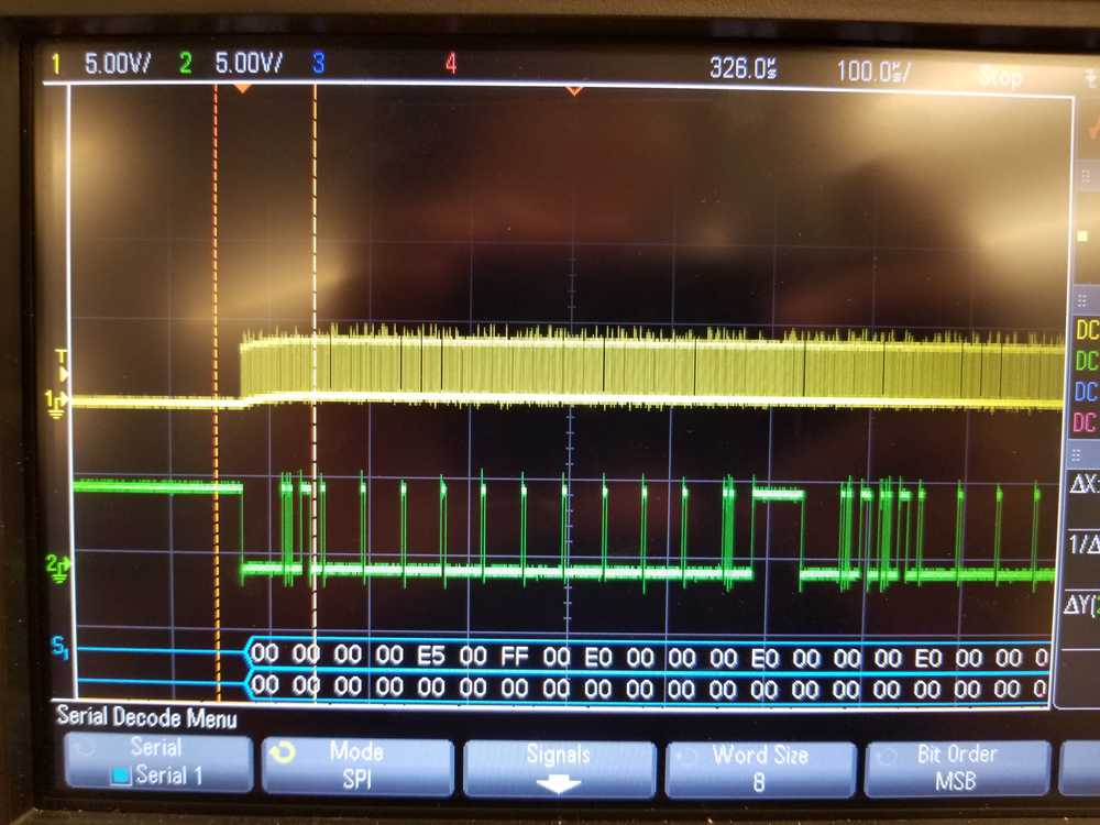
As you can see in the above picture, we have 4 bytes of 0, which is the start frame, then we have 4 data bytes that are:
- Brightness - First 4 bits are the start bits that have to be 0b1110. Brightness is only set by 4 bits. In this case we can see that the first byte is 0xE5 = 0b11100101. 0101 in binary is decimal 5, which was the brightness setting that I had programmed.
- Blue LED = 00
- Green LED = FF = 255 Max Green value
- Red LED = 00
So data to the first LED seemed fine, as I continued scrolling through the other frames I found that not all the "second batch" of signals had started before the first batch could complete!
So I added tiny delays to my functions that made them look like this:
xxxxxxxxxxvoid Write (uint8_t c) { int i=0x80; //0x80=0b10000000 while (i) { if (!(c & i)) PORTB &= ~(1<<PB1); // set Data low else PORTB |= (1<<PB1); // set Data high //ADD DELAY here to ensure data bit is set high _delay_us(1); PORTB |= 1<<PB0; // set Clk high i = i>>1; _delay_us(1); PORTB &= ~(1<<PB0); // set Clk low }}void AllBlue (uint8_t brightness) {ClearBuffer(); for (int d=0; d<LEDs; d++) { Display[d][0]=brightness; Display[d][1]=255; Display[d][2]=0; Display[d][3]=0;} UpdateDisplay(); _delay_ms(10); //Delay to ensure data passing is accurate}With these additions, the watch could happily tell time and respond to a touch input!
Horray.
Note on Project scope and time management
I started out with a grand notion to create an affordable DIY smartwatch that could cost ~ $15. However, I'm running out of time now. So while my watch started out very smart, it progressively dropped in IQ and right now it had decided to be a watch. A customizable watch no doubt, but still, a watch.
Final Integration
It is now time to put everything together...
Voltage, power and current.
During testing iterations I discovered that the LEDs don't behave very well with 3V (which was what the CR2412s flat button cells provide). So I decided to make a regulator board and stack two 3V cells, and use the 5V regulator to bring down the voltage to 5V where everything was happy!
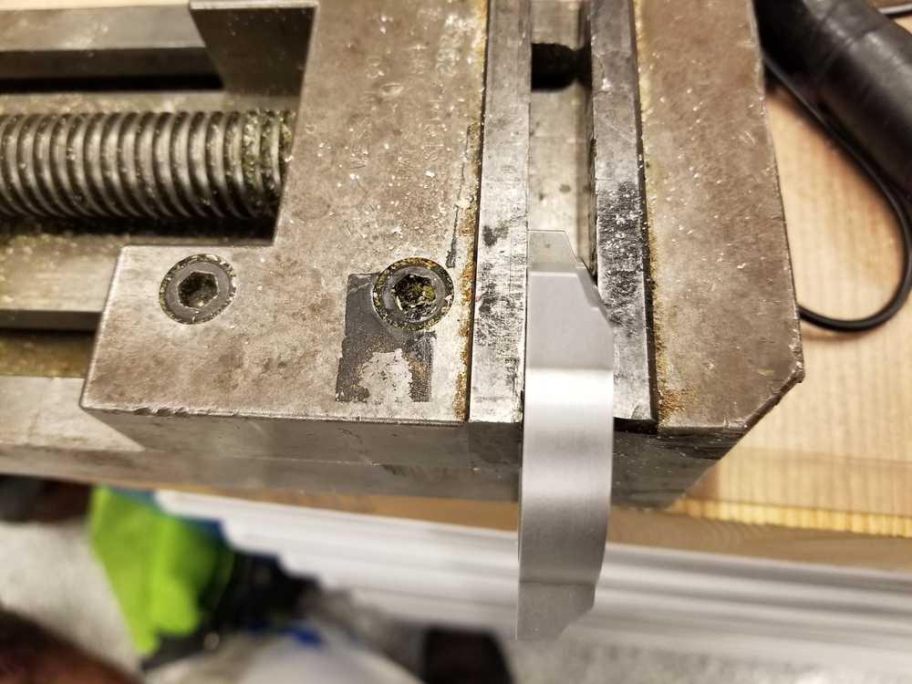
Attaching straps to the watch body
Since I was super protective, and didn't want the the EDM machine to make line cuts in order to access the points to make holes for the straps to fixture onto the watch casing, I had to do so manually using a drill. So I very carefully fixtured the casing and then did this...
Finally putting it all together
Acknowledgements
Many thanks to my sections mates for all the wisdom and support, and a special shout out to Zach and Ben for all the troubleshooting and sharing of knowledge. Learnt so much this sem.