Week Final - Force Feedback Control
Final Demo
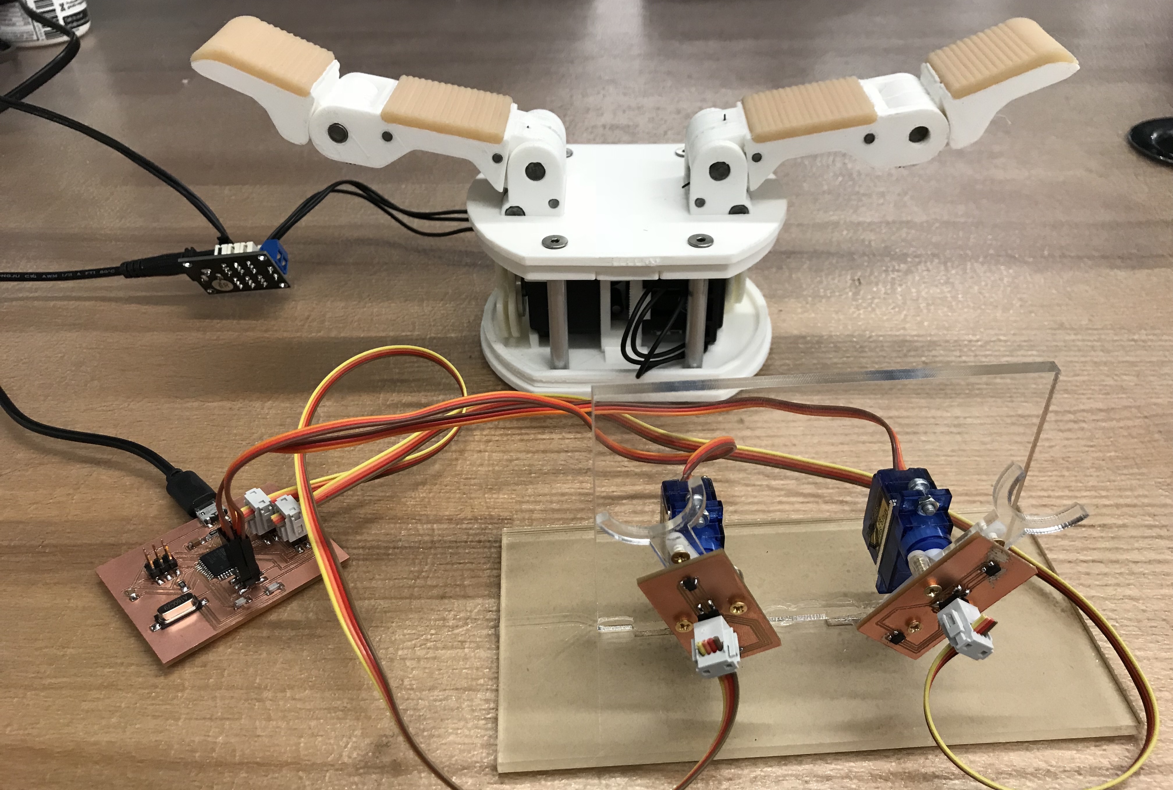
Goal: Design a device that can provide force feedback from robot hand to human hand.
Applications:
- Robot teleoperation for remote rescue/surgery task
- VR/AR wearable device with force feedback
Demo:
Features
- Micro-controller: ATmega16U4
- USB-support: Based on LUFA USB library
- Hardware PWM: Two servo motors control
- Force Sensing: Hall-effect sensors & magnet
- Higher Precision: Apply 2 Hall-effect sensors for increasing force sensing precision (10x) and cancelling earth magnet.
- Serial Communication: Between 2 controller (ATmega16U2 & U2D2) and PC
- 3D-Printed cable-driven robot hand
How does it works?
Core technique: Elastic Servo
The regular hobby servo motor (e.g. SG90) can work in either way:
- Detached (PWM = 0). It can be moved freely, but we can not read the position of it directly.
- Attached (PWM = 1~2ms during 20ms). It will hold to the given position, but cannot be moved.
However, what I need is:
- When it’s moving, knowing the position of the servo motor all the time (To continuously control the robot hand)
- When it’s holding, I can move it when I exert certain amount of force (based on robot hand’s load)
The way I solve this is: adding a force sensor on the servo motor!
We can maintain the position of the servo motor, and update the position based on the force sensor input. Specifically, when the force is detected, then we can change the motor position to the corresponding direction. In this way, we can get the position of the servo motor all the time while moving it freely, and the servo motor can provide brake and moving speed to give us force feedback! Problem solved.
(Story Behind):
Actually during the final project development period, I figured out that there could be 3 possible ways to solve the problem, so I have to make a choice (since time is limited):
Plan A: Add a force sensor to the servo motor. (But Neil suggests that the force sensor part is not reliable, I need to make my own force sensor)
Plan B: Read the servo motor’s current to infer the torque. (Since there should be much noises in the current, there will be more of signal processing involved)
Plan C: Change to use robot servo like Dynamixel motor, which can provide infered torque and provide position when detached. (However, it will be much more expensive, and will be less challenging for the class & AVR).
After considering, I chose the the Plan A, because I found more materials on the Internet, and it will be more suitable for a final project. But in the future, if I have opportunity, I would also try the Plan B & Plan C, they may have less space contraints.
Servo Control
For the servo motor control, I tested both software & hardware PWM on ATtiny44. Both work well. Then I move to ATmega16U4.
Since I need to control two servo motors at the same time, I chose hardware PWM to make the control frequency higher. Based the datasheet of ATmega16U4, there’re several PWM timer: OC0(8-bit)/OC1/OC3(16-bit)/OC4(10-bit). I used 16-bit PWM OC1A & OC1B for my servo control.
Servo module (Adapted from Neil’s code):
#define output(directions,pin) (directions |= pin) // set port direction for output
#define clear(port,pin) (port &= (~pin)) // clear port pin

#define PWM_port PORTB
#define PWM_direction DDRB
#define PWM_pin_1 (1 << PB5)
#define PWM_pin_2 (1 << PB6)

void servo_move(double pos1, double pos2){
   double angle1 = pos1 / 180.0, angle2 = pos2 / 180.0;
   int t1 = ceil(500 + angle1 * 2000);
   int t2 = ceil(500 + angle2 * 2000);

   OCR1A = t1;
   OCR1B = t2;
}

// set output direction

clear(PWM_port, PWM_pin_1);
output(PWM_direction, PWM_pin_1);

clear(PWM_port, PWM_pin_2);
output(PWM_direction, PWM_pin_2);

// set PWM configuration

TCCR1A = (1 << COM1A1) | (0 << COM1A0) | (1 << COM1B1) | (0 << COM1B0); // clear OC1A & OC1B on compare match
TCCR1B = (0 << CS12) | (1 << CS11) | (0 << CS10) | (1 << WGM13); // prescaler /8, phase and frequency correct PWM, ICR1 TOP
ICR1 = 20000; // 20 ms frequency
The ICR1 value need to be calculated. I’m using 16MHz clock, and PWM prescale /8, and using frequency correct PWM mode (which means the timer will go up and down, so ICR1 needs /2), and the servo motor works at 50 Hz (1s/20ms), so the ICR1 is:
ICR1 = 16Mhz / 2 / 8 / 50 = 20000
Ideally, the servo motor will take 1~2ms in 20ms for 0~180 degree. However, in practice, I found my motor (SG90) have slightly different range(0.5~2.5ms in 20ms). So I adjust the PWM module range.
And to see what the signal looks like, I probe the data in the oscilloscope, and get very beautiful figures:
And the servo motor moves as expected!
Force Sensing
The next step is adding force sensor. Since Neil metioned the force sensor component tends to be noisy, so I decided to make my own force sensor using magnet and hall-effect sensors.
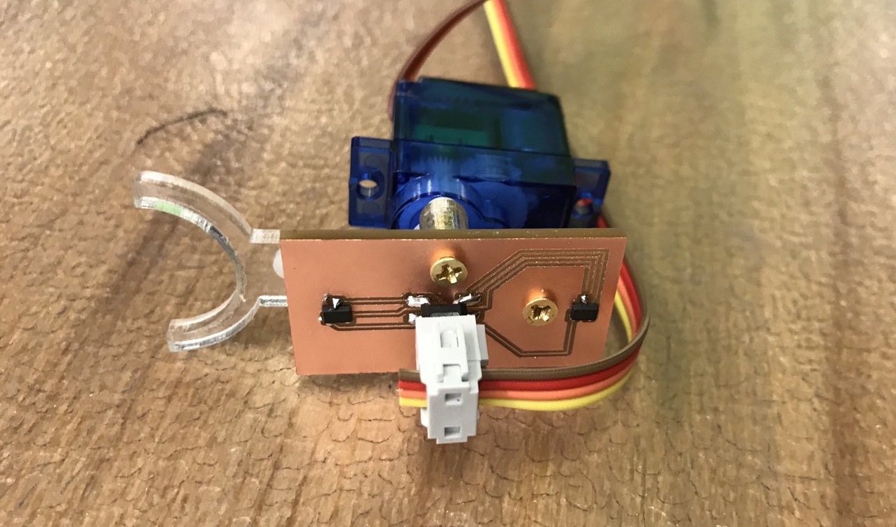
Force Sensor == Spring + Magnet + Hall-effect Sensor
By attaching the magnet on a bendable stick (acts like a spring), we can detect the force: the larger the force, the larger displacement of the magnet, therefore the larger change of the magnetic field.
First attempt
The first thing I did is to test whether hall-effect sensor can detect this sensitive movement. So I test on the ATtiny44, and stick the magnet to servo horn using hot glue.
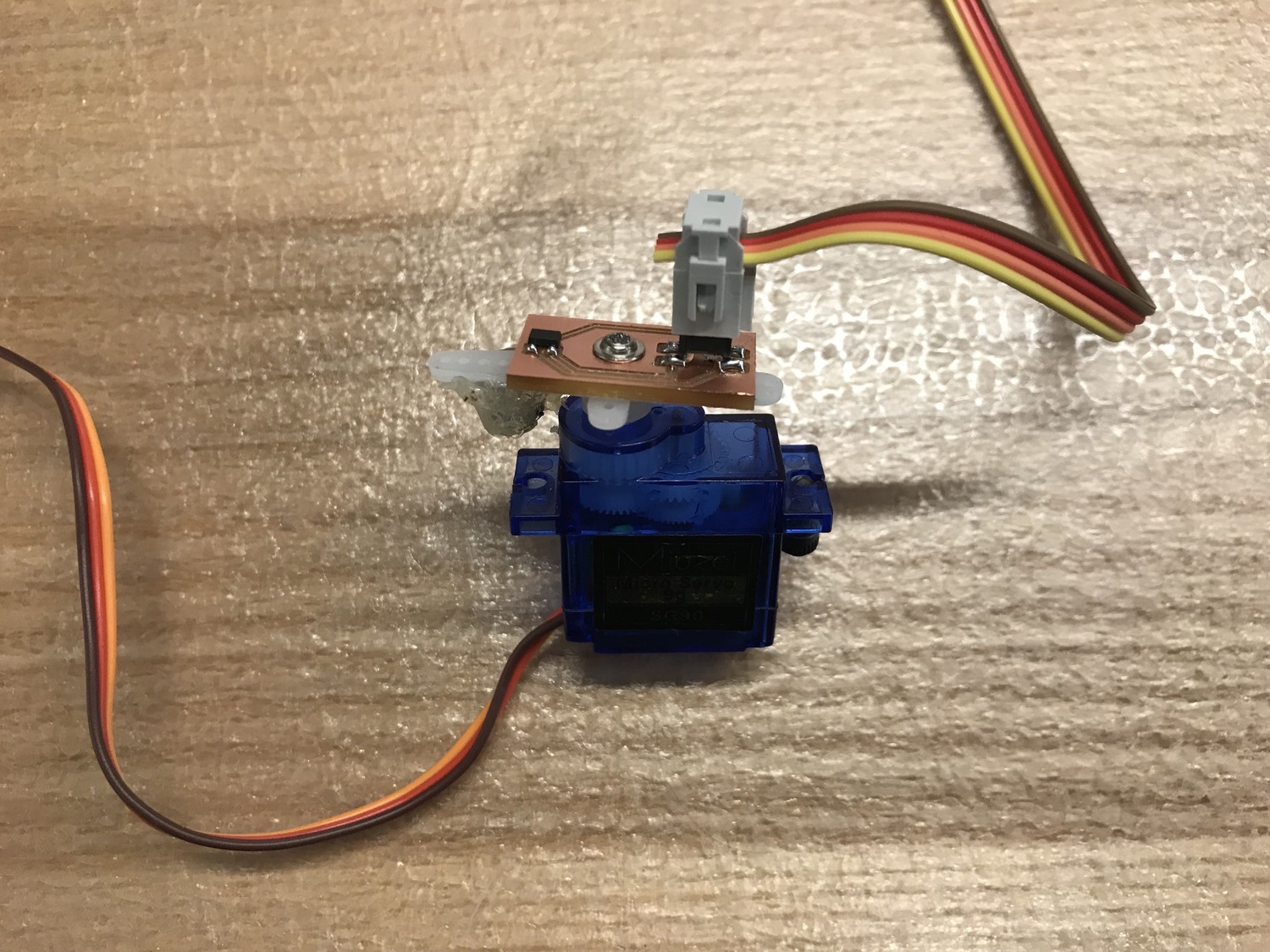
And the result is that hall-effect sensor can detect the sensitive movement of the magnet!
However the ADC reading will only change about +/-5 and can be effected by earth magnetic field (+/-1) when changing the orientation.
Improvement
Circuit
Inspired by light sensors, to make it more sensitive, I decided to use two hall-effect sensors and using ADC amplifier to magnify the difference between them (20x).
And, then I use the ATmega16U4 for higher communication speed. I had a ATmega16U4 board from the Wildcard week, which have 4 general pins. However, to use the ADC magnifier, ATmega16U4 only supports negative pin to be ADC0/ADC1. It support 10x, 40x, 200x. So I redesign the board and using ADC5-ADC0, and ADC4-ADC1.
Coupling
One strange thing happens when I use the amplifier. It works well individually on the 40x(ADC5-ADC0), and 40x(ADC4-ADC1), however, when they’re used together, changing one will change the other one. Ben suggests it could because there’s coupling between the pins. The amplifier not only magnify the value, but also magnify the noise. So I change the 40x to 10x, and the problem disappeared. In the future, could add some capacitors between when using large amplifier.
Connection
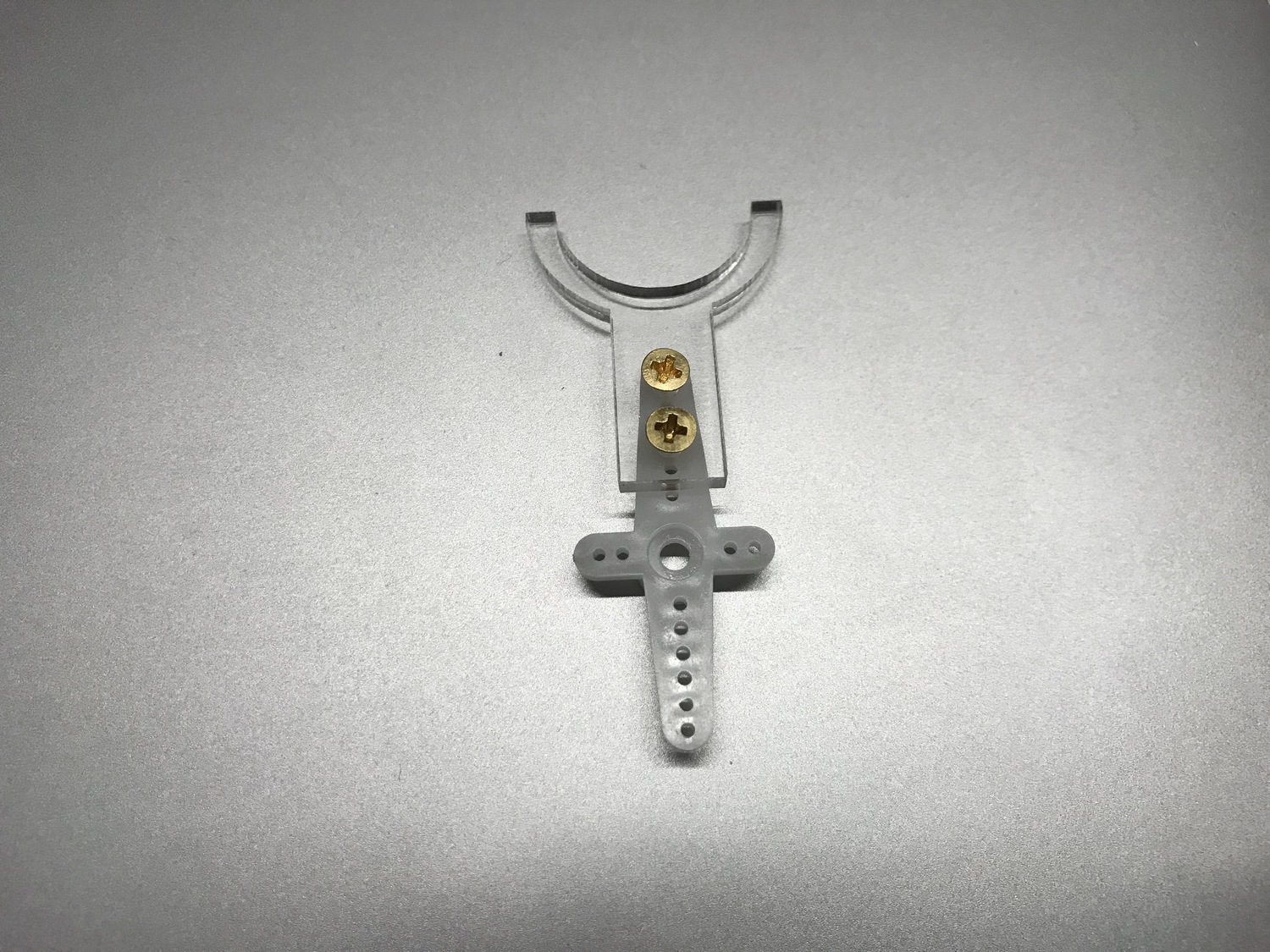
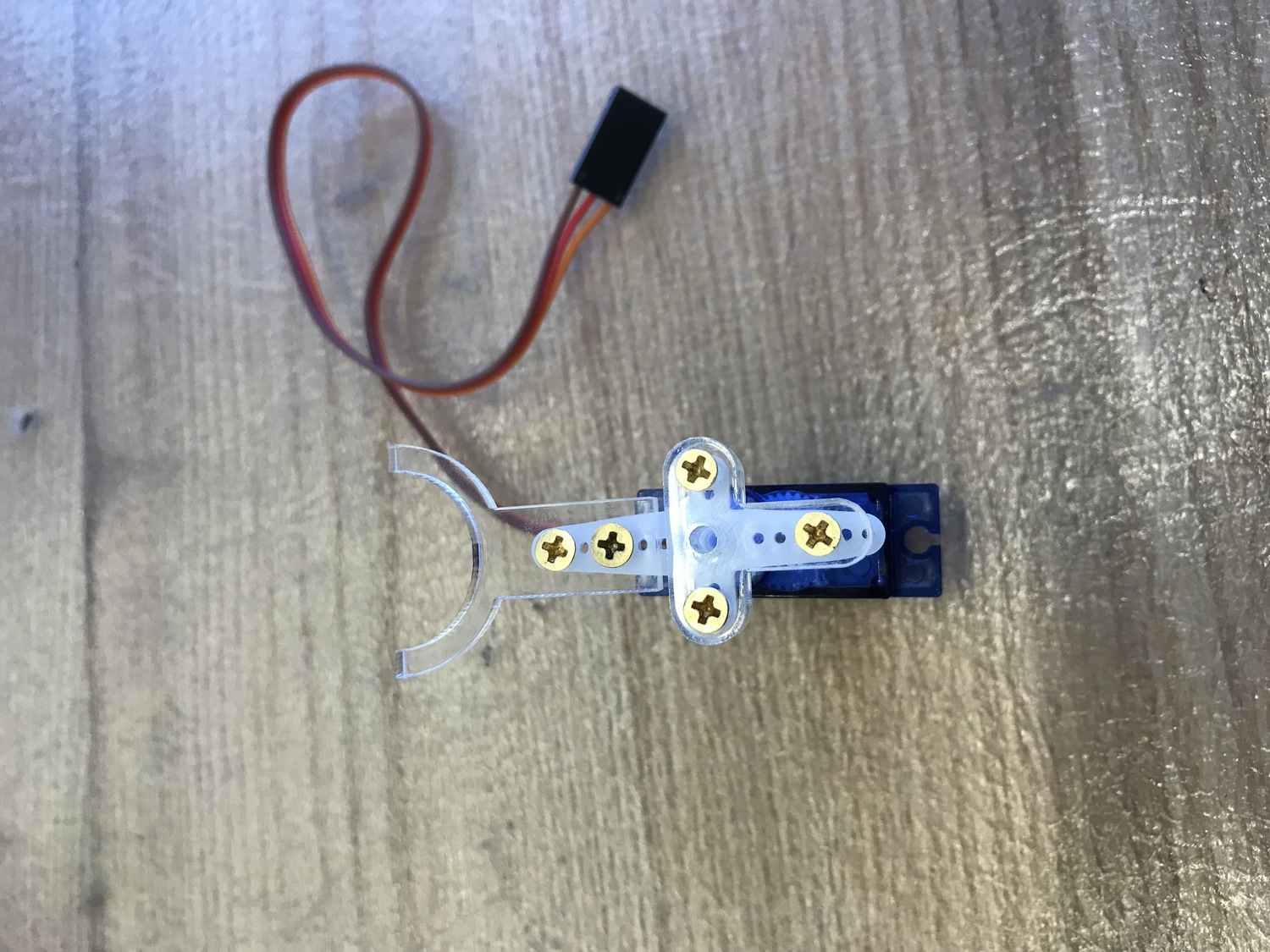
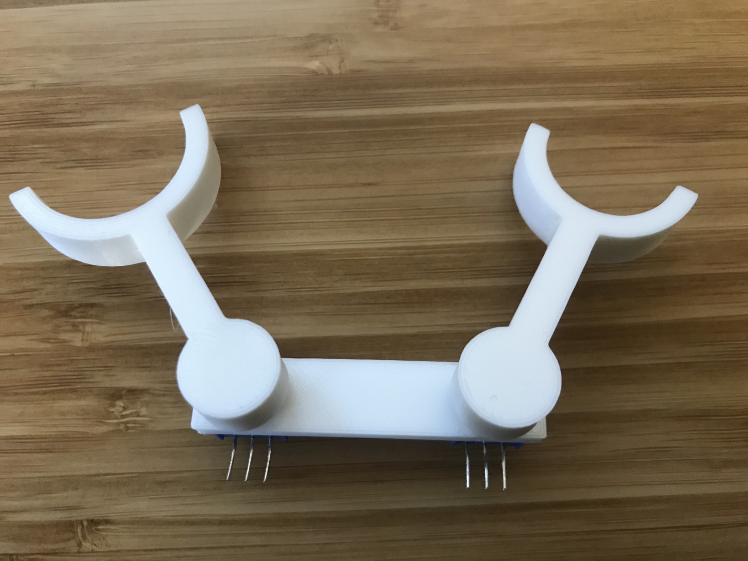
Furthermore, to make the magnet connected to the servo more stably, I laser-cut some acrylic part, so that the magnet can sit in the acrylic, and also provide handler for human to move.
The SG90 Servo Motor has the screw with it, but to use longer/shorter screw, we need to find some other screws. The hole on the horn is very small, it’s difficult to directly put M2/M3 into it. The way I used to connect the acrylic part and the servo horn is using wood scrow to self-tapping. The SG90 horn is quite flexible, and is designed to be self-tapped in. Here’re some pictures:
And to attach the PCB board to the servo, I drilled 3 holes on the PCB board and use wood screw to connect it to the servo horn. The key feature I learned is that: Eagle’s unit for the drill/pad/distance is mil. And I used 1/16” end-mill in my case (for hole with diameter of 2mm).
Force sensing module.(Adapted from Neil’s code)
int read_force1(){
   double accum1 = 0, accum2 = 0;
   int count = 0;

   ADMUX = (0 << REFS1) | (0 << REFS0) // Vcc ref
      | (0 << ADLAR) | (0 << MUX4) | (1 << MUX3) | (0 << MUX2) | (0 << MUX1) | (1 << MUX0);
   ADCSRB = (1 << MUX5);
   // MUX5:0 = 101001; 10x (ADC5 - ADC0)

   ADCSRA = (1 << ADEN) // enable
      | (1 << ADPS2) | (0 << ADPS1) | (1 << ADPS0); // prescaler /32

   for (count = 0; count < nsamples; ++count) {
      //
      // initiate conversion
      //
      ADCSRA |= (1 << ADSC);
      //
      // wait for completion
      //
      while (ADCSRA & (1 << ADSC))
         ;
      //
      // add result
      //
      accum1 += (ADC * 1.0 / nsamples);
   }

   return ceil(accum1);
}
Just for fun: Anti-social motor (The motor will move to the opposite direction of the pushing force):
Elastic Servo
Combining the force sensor with servo control, I made elastic servos.
I applied a simple control method which works greatly for demonstrating force feedback. But it could be furthermore improved with PID control.
force1 = read_force1();

if (fabs(force1 - force_avg1) > tol1) {
	if (force1 > force_avg1) {
		pos1 = pos1 - sensitivity_pos1 * (force1 - force_avg1);
	}
	else{
		pos1 = pos1 - sensitivity_neg1 * (force1 - force_avg1);
	}
	pos1 = max(min(pos1, 180.0), 0.0);
}

servo_move(pos1, pos2);
And after getting the torque information from robot hand (Dynamixel MX-28T motor infered torque from current), I would change the sensitivity so that when the robot’s torque is large, the SG90 will be harder to move, therefore provide force feedback.
And the main control part is finished here. Praise!
USB support (Virtual Serial)
I like the USB support a lot for two reason:
- Micro-usb cable. I can communicate with the micro controller with micro-usb instead of FTDI cable ($2 vs $17).
- Faster communication speed. In my test, ATmega16U4 can work on 115200 virtual serial communication, and recieve, parse then send back 2500 lines (2 integers) per seconds, which is much faster than ATtiny44.
I learn this from wildcard week from Ben’s tutorial.
(Story Behind)
In fact, the wildcard week literally SAVED the final project.
While almost all the parts of the elastic motor works well on the ATtiny44, there’s one last most crutial component: sending the robot torque information back to micro-controller. I didn’t know the exact reason why the software serial will become much slower when parsing the whole line. (Maybe because have no buffer?). In my case, from the PC end, I have to send one character then wait for 2ms to send another character, which leads that I could only recieve ten lines per second. This is too slow for robot real-time control.
Fortunately, I happened to test the virtual software from ATmega16U4, and the speed is very satisfying. So I made a decision to change to use ATmega16U4 for the final project, and it works perfectly for me. It can recieve, parsr then send 2500 lines per second. So I’m really glad that I choose to take the USB profile in the wildcard week!
Communication
To guarantee low latency, I chose the serial communication.
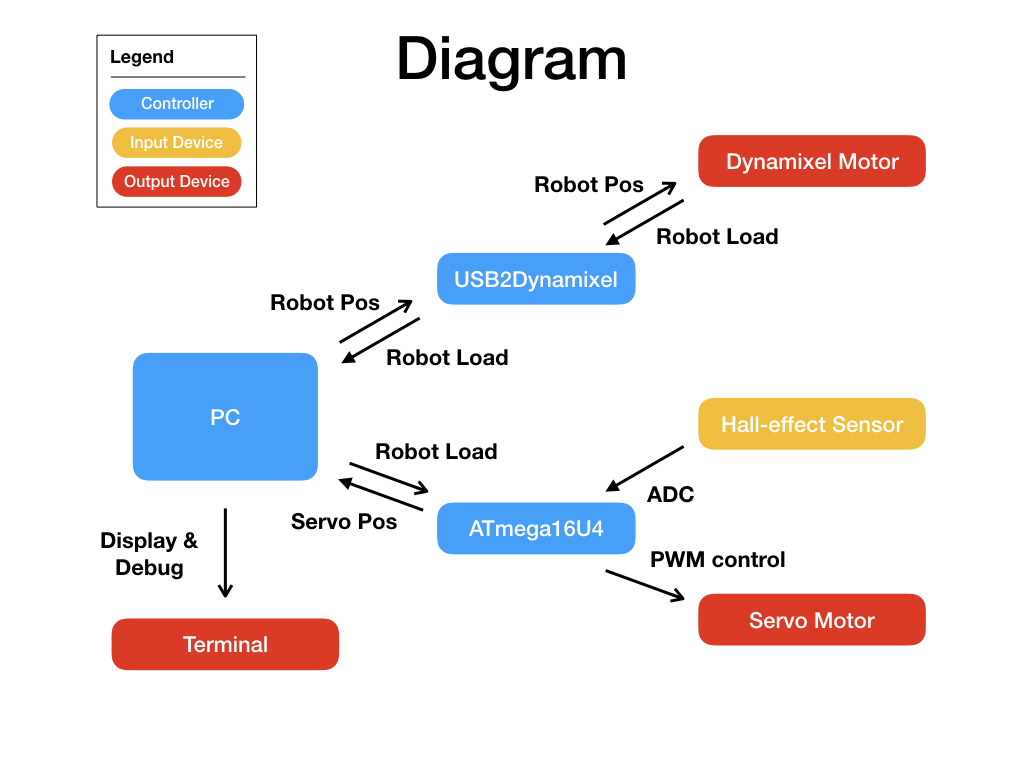
The whole diagram is shown as following:
There’re one main controller (PC) and two micro-controller (ATmega16U4 is the AVR board I designed, the USB2Dynamixel is the bought controller for the dynamixel).
The PC will have two serial communication with each of the micro-controller. And to have higher frequency, I used multi-thread for communication.
The LUFA VirtualSerial is written by interrupt, each time fscanf only takes one character. So I wrote the line character parsing module for receiving then sending data.
Communication module
int chrs[20]={0};

void parse(int *chrs, int *x, int *y) {
	*x = *y = 0;
	int i = 0, flag = 0;
	int sgn = 1, t = 0;
	while(i<20 && chrs[i] != '\n') {
		if (chrs[i] == '-'){
			sgn = -1;
		}
		if (chrs[i] == ' '){
			*x = sgn * t;
			flag++;
			sgn = 1;
			t = 0;
		}
		if (chrs[i] >= '0' && chrs[i] <= '9') {
			t = t * 10 + chrs[i] - '0';
		}
		chrs[i] = 0;
		i++;
	}
	*y = sgn * t;
	chrs[i] = 0;
}


int16_t ReceivedByte = CDC_Device_ReceiveByte(&VirtualSerial_CDC_Interface);

if (!(ReceivedByte < 0)) {
	chrs[i++] = ReceivedByte;
	if (ReceivedByte == 10) {
		parse(chrs, &x, &y);
		// change the sensitivity for the servo motor control
		// send current servo motor position & force
		fprintf(&USBSerialStream, "%d %d %d %d\n", pos1, pos2, force1, force2);
		i = 0;
	}
}
Code
Source code (will be convenient to compile when putting the final folder in the LUFA/Demos/Device/ClassDriver/)
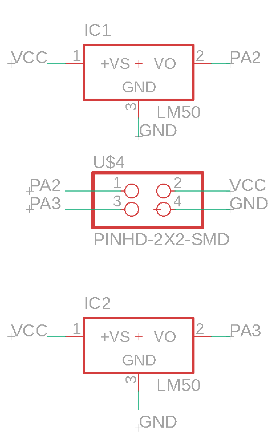
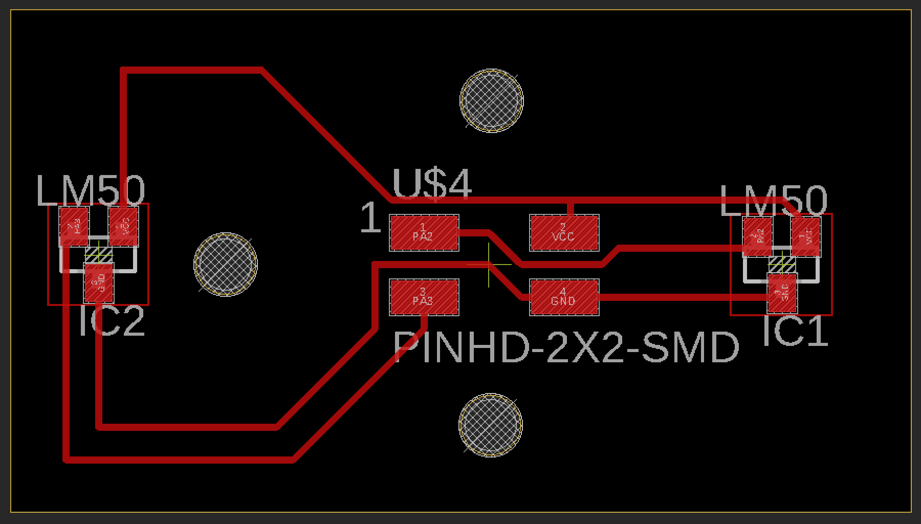
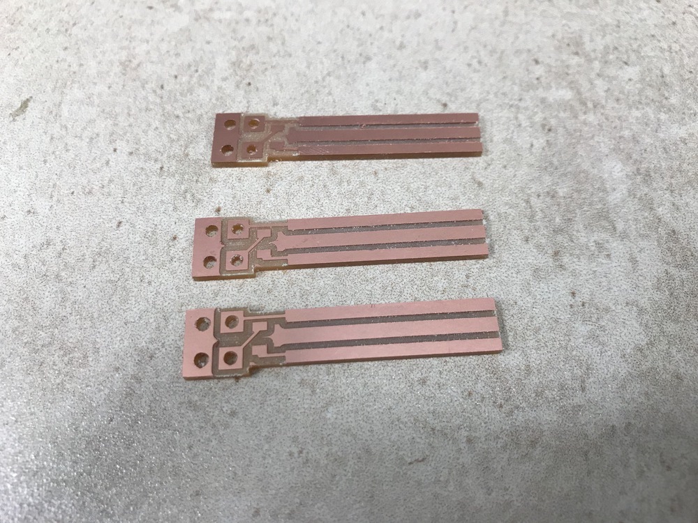
PCB Design
The ATmega16U4
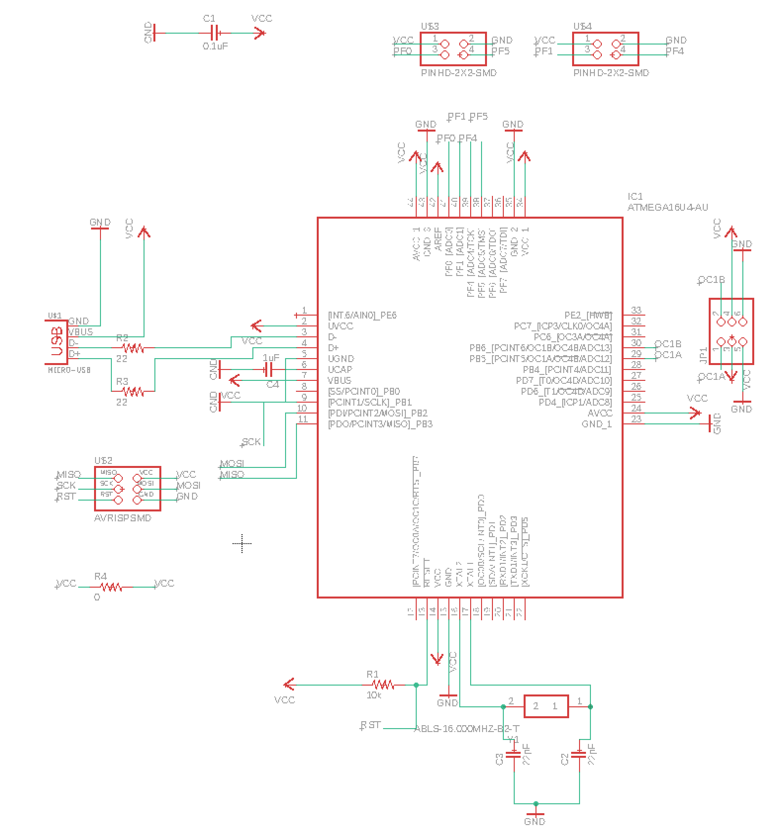
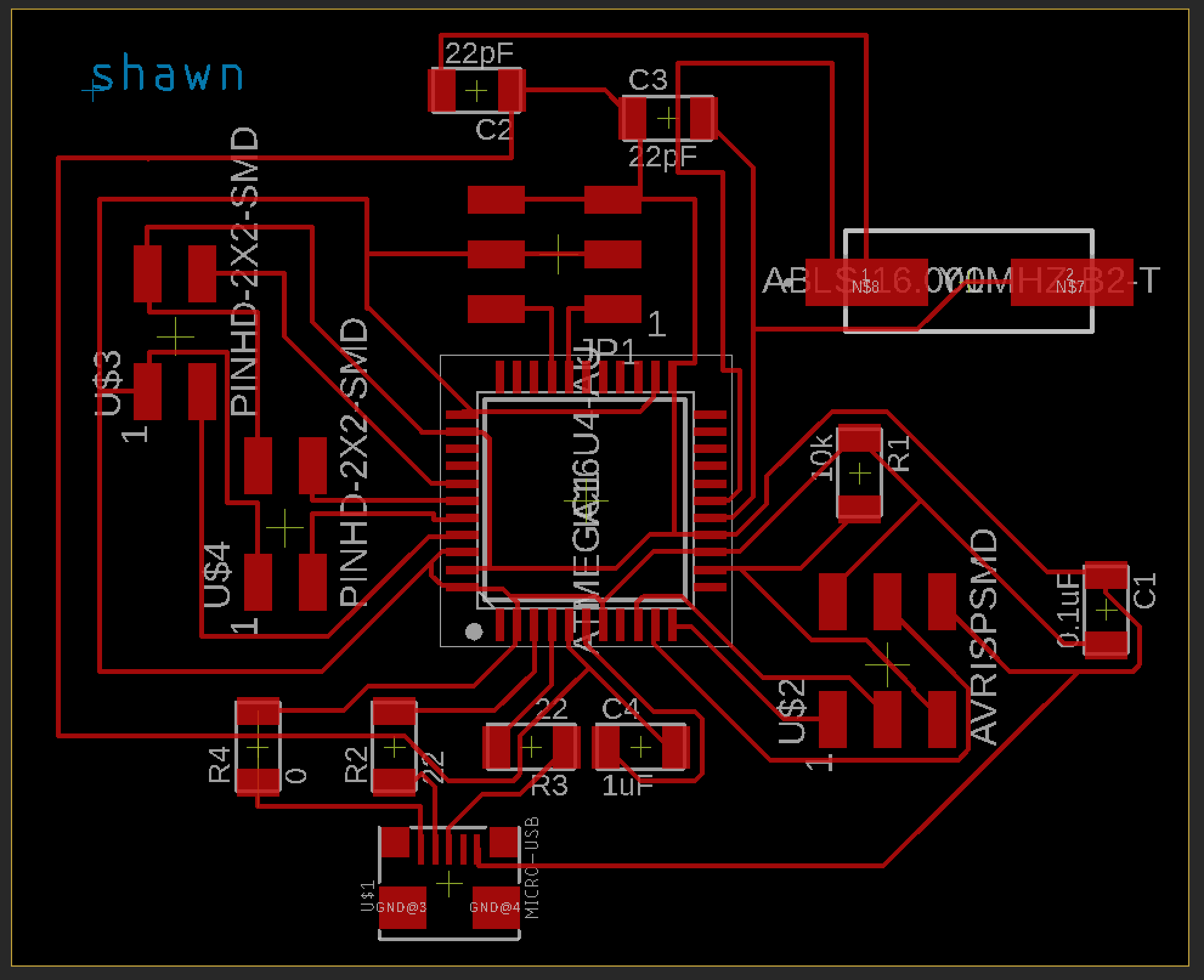
2 Hall-effect sensor. Hole size: 90 (mil). Hall-effect sensor lies in Eagle library linear->LM50 (or search SOT-23).
Project Log
Update 12.17 (Final Countdown)
- Read ADC from the sencond motor (Done)
- Read stiffness from PC serial (Done)
- Tranform motor torque into stiffness (Done)
- Improve control parameters (Done)
- Making case (Optional, if time permitted)
Update 12.16
TODO
- Draw new ATmega16U4 board for ADC & PWM. (DONE)
- Fabricate the PCB (DONE)
- Test PWM1/3 for ATmega16U4 (DONE)
- Make two servo motor force sensor board. (DONE)
Update 12.15
TODO:
- Control one robot finger with the servo motor Succeed
- Make the board for two servo motor Tomorrow
Today I spent most of time on bi-directional communication. Since I need high-frequency control, the delay for serial communication have to be low.
After working on software
- ATmega16U4 ADC reading
The ATmega16U4 can read ADC0-ADC13. And can choose 1x, 10x, 40x, 200x. However!!! It can only be ADC4/5/6/7 - ADC0/1.
COM1A1:COM1A0 = 10, Non-invert Mode
Mode: WGM13:10 = 1000, PWM, Phase & Freq. Correct.
TOP: ICR1 = F_MCU / Servo_frequency / 2 / N (pre-scaler)
e.g. 20,000,000 / 50 / 2 / 8 = 25,000 (for 20 ms frequency)
Duty: OCR1 = ICR1 * duty
e.g. 25,000 * 10% = 2,500 (2 ms PWM on time)
- ATmega16U4 serial works! 115200 baudrate & can read & send back 2500 lines (2 integers) per seconds.
- ATmega16U4 ADC7 works!
Update 12.13
For servo motor, what’s the relationship between PWM and angle
during 20ms period, min 1ms; max 2ms; 1.5 ms is the neural (center) position.
Update 12.12
Useful links:
Using spring + magnet + hall effect sensor to work as force sensor!!
In eagle, change the grid size by using command:
grid grid_size
Update 12.11
Successfully control the servo motor with ATtiny44. Send 0 to PWM will make the motor move freely.
Update 12.5
Update PID control for Dynamixel & Optimize the pipeline to reduce the delay.
Design the holder for the potentiometers.
Update 11.28
Add control component and user interface into the final project.
Control the openhand with web client.
Control the hand with potentiometers.
More details in Week 12 User Interface
Update 11.11
Since I plan to handle analog camera input. In this week, I studied the NTSC and output the NTSC video to a monitor!
Update 11.8
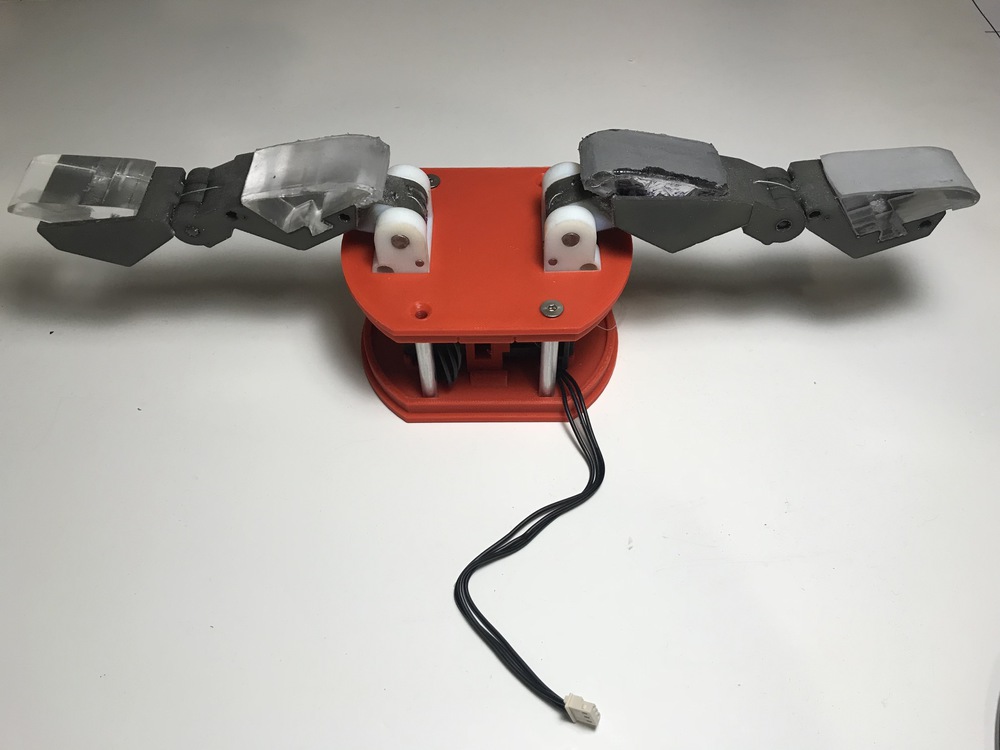
3D printed the OpenHand parts and assemble with the GelSight finger.
Update 11.5
Discuss with Ben and Zack. Discuss the possiblity to read analog camera and send the video back to computer by wire/wifi/bluetooth.
NTSC analog camera
Ben suggests that there’re video decoder on the Digi-Key. Already ordered.
Wifi communication
Will study.
Update 10.31
(This part is mixed with my research project, but it’s highly correlated to the final project)
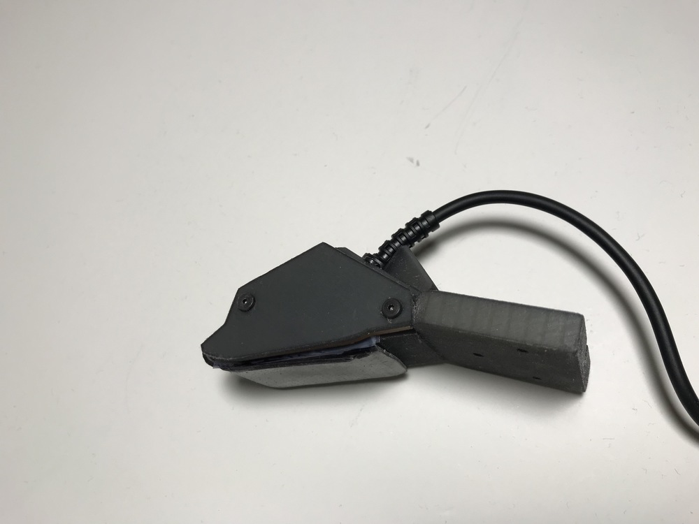
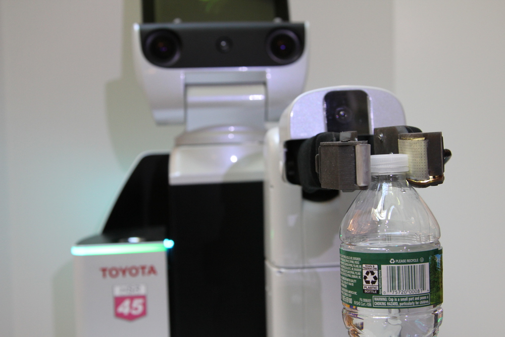
The new-design of the Gelsight tactile finger is mounted on the Toyota HSR(human support robot).
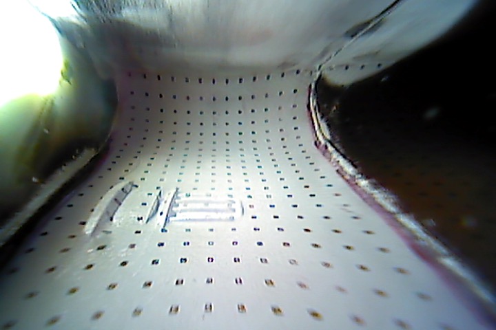
These two images are the example of holding a bottle and the tactile signal from the finger.
Update 10.16
Making a 3d printed part to hold the acrylic. It’s press-fit.

Update 10.15
A LED strip with a resistor. This is used to light up the acrylic.
Update 10.11
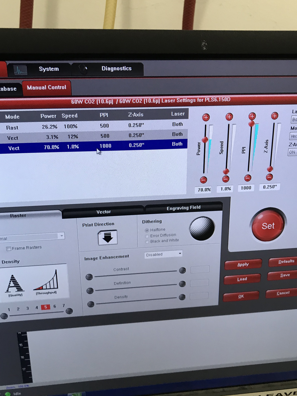
Making the 1-inch thick acrylic block for the finger.
1-inch is very thick for the laser cut, some times it will catch on fire. I tried different parameters in laser cutting machine (Power & Speed). After experiments, I could cut the acrylic with 4 passes with (power: 70%, and speed 1.0%).
After sanding it and use Dremel to polish it, here’s acrylic block:

Background
- Our lab is developing a camera-based tactile sensor called GelSight (MIT News).
 Silicone Gel
- Yale published an open-source robot hand called OpenHand (Website)
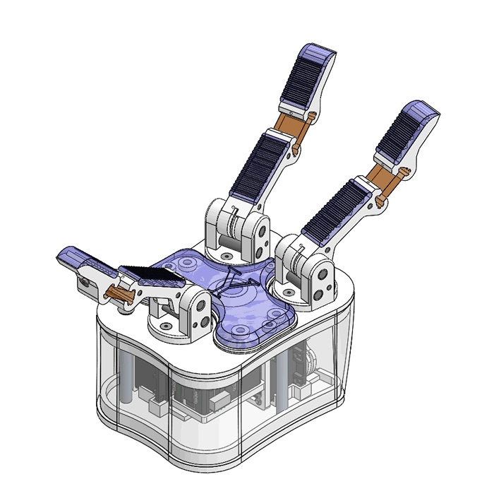
Goal
- Design a modified OpenHand finger (or hand) with GelSight inside.
- Design a demo to control the finger with the tactile information.
Requirements
- CAD (Solidworks) draw the cover to connect the bone of finger, camera, silicone gel, and camera.
- Laser cutting cut the clear acrylic to connect slicone gel and the bone.
- Mold and Casting (Silicone) cast silicone into a mold and cure with the acrylic inside.
- PCB (LED) design PCB board to connect LED and resister to project uniform lighting.
- Motor control the motor to drive the finger.