Week 3 - Eletronics Production
This week’s assignment was less open-ended. We had to make an in-circuit programmer as decribed in the instructions here.
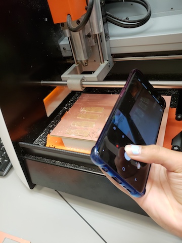
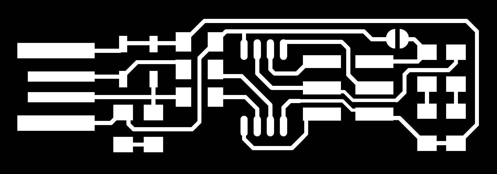
After the training session, a group of us decided to team up and produce 4 boards at once, saving time on configuing the mill and switching out bits, and solving the problem of who gets to use the mill first. We used the 1/64” endmill to mill the traces and the 1/32” endmill to mill the outline.
This was successful, and in a little under an hour, the four of us all had shiny new boards, ready to solder components onto.
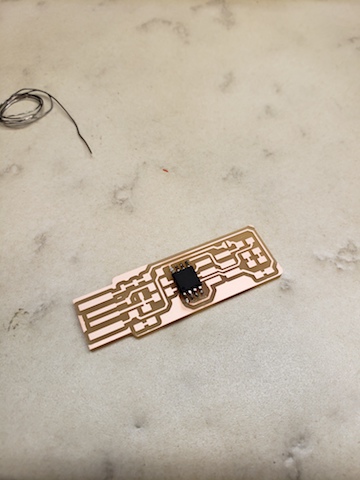
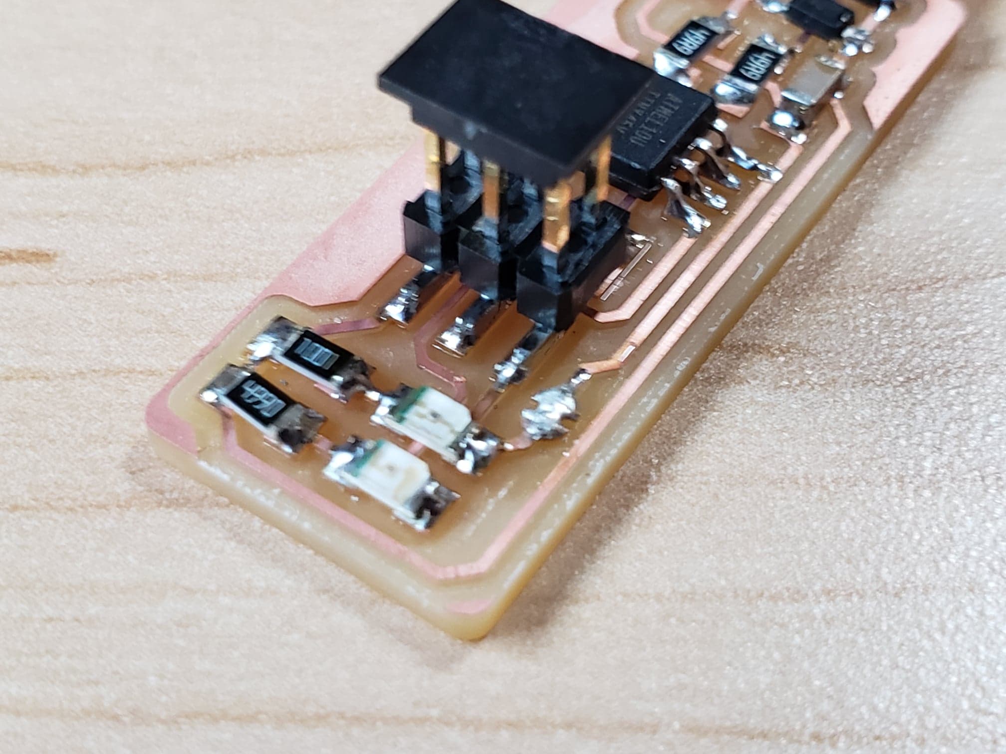
Turns out the components are tiny. Like realllly tiny. Having not really soldered before, I found placing the components to be difficult, as my hands would shake. However, I soon got the hang of it and was on my way! May my joints be smooth and shiny enough.
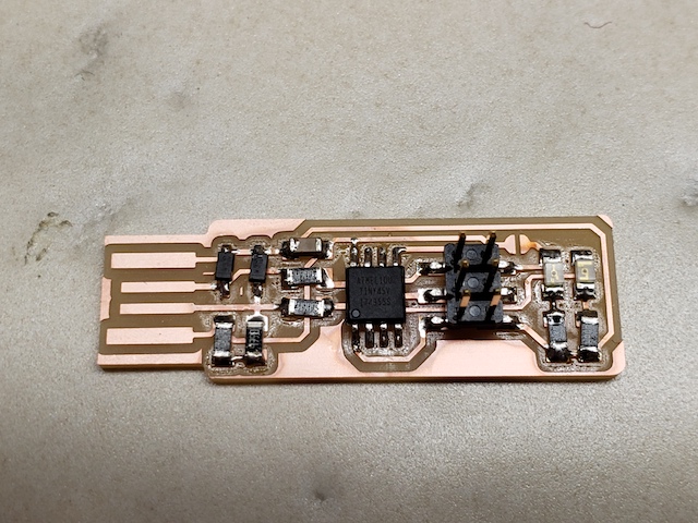
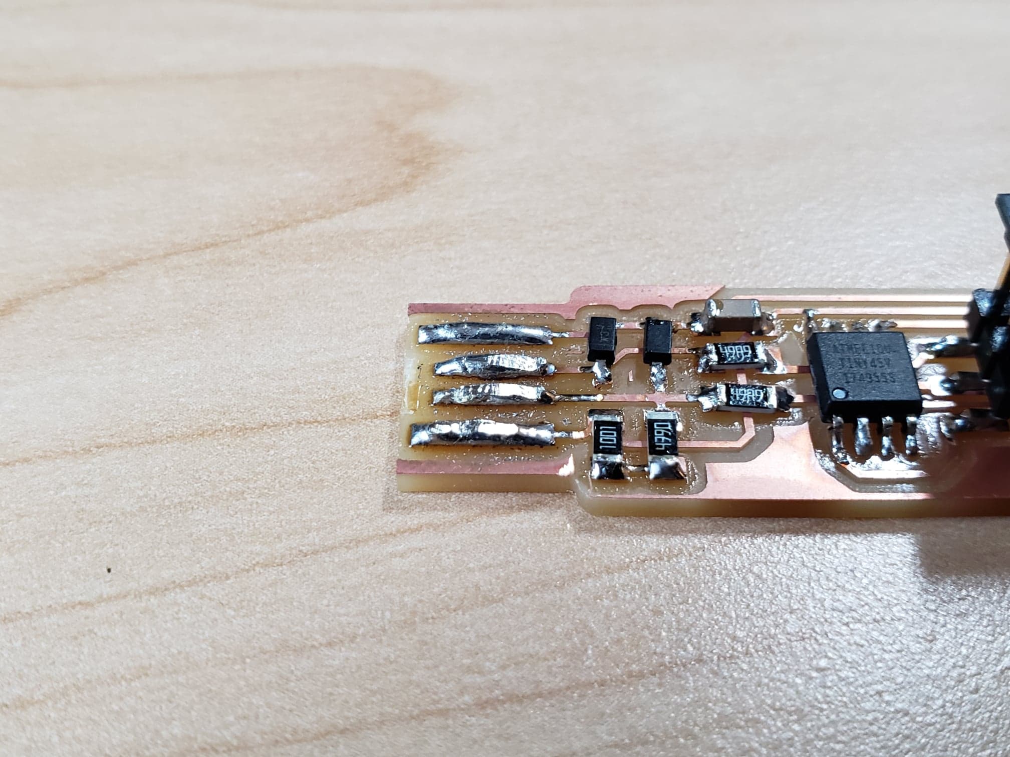
Next, I had to load the program onto the PCB. In order to do this, I needed to pad the USB connector with extra solder because they were a little thin, and create a bridge connecting the V_{cc} to the V_{prog} pin on the ISP header so that the board can be programmed. Afterwards, I severed this connection to turn the board back into a programmer.