Week 5 - Electronics Design
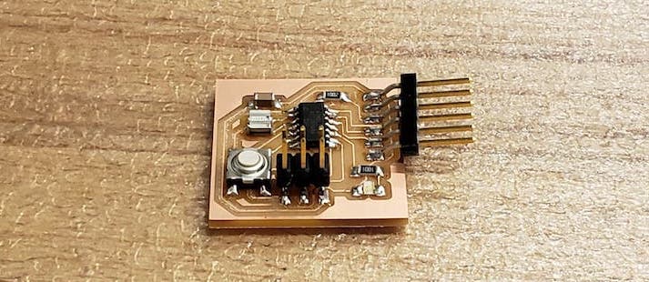
This week’s assignment was to design our own hello world board, going off the examples given to us by Neil, and add a button and an LED. The finished board would echo back any input we give it.
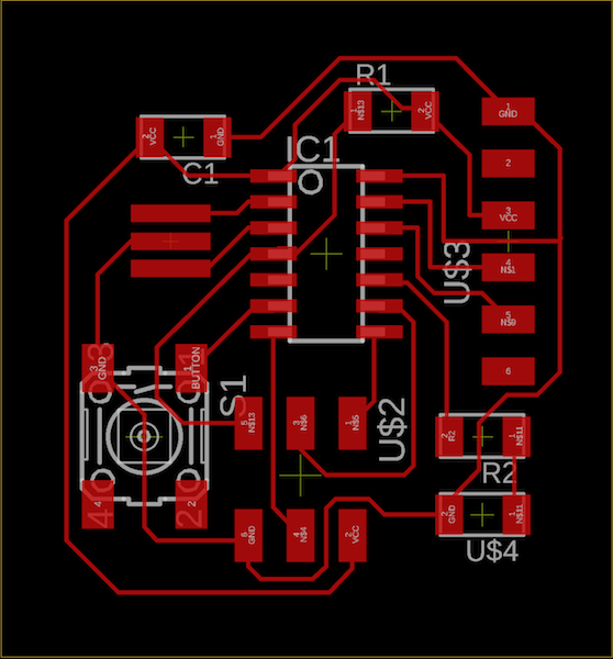
I used EAGLE to design my circuit board. Understanding which exact components to use was tricky from the pictures we were given, but sites from previous years came in handy. Drawing the schematic took maybe 30 minutes.
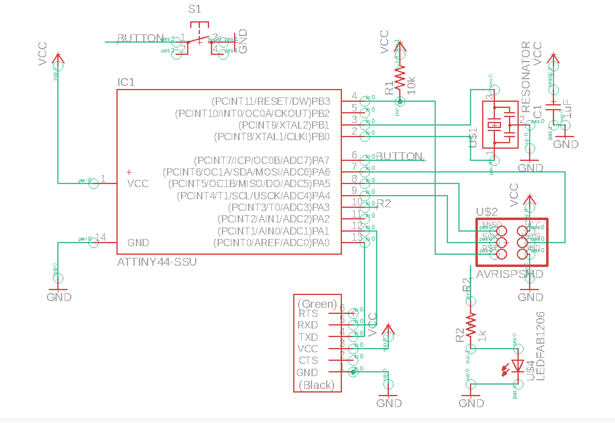
Components list:
- Attiny44
- ISP 2x3 header
- Resonator
- 1 µF capacitor
- 10k resistor
- 1k resistor
- Blue LED
- 6mm switch (button)
- 1x6 pinout
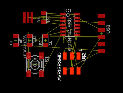
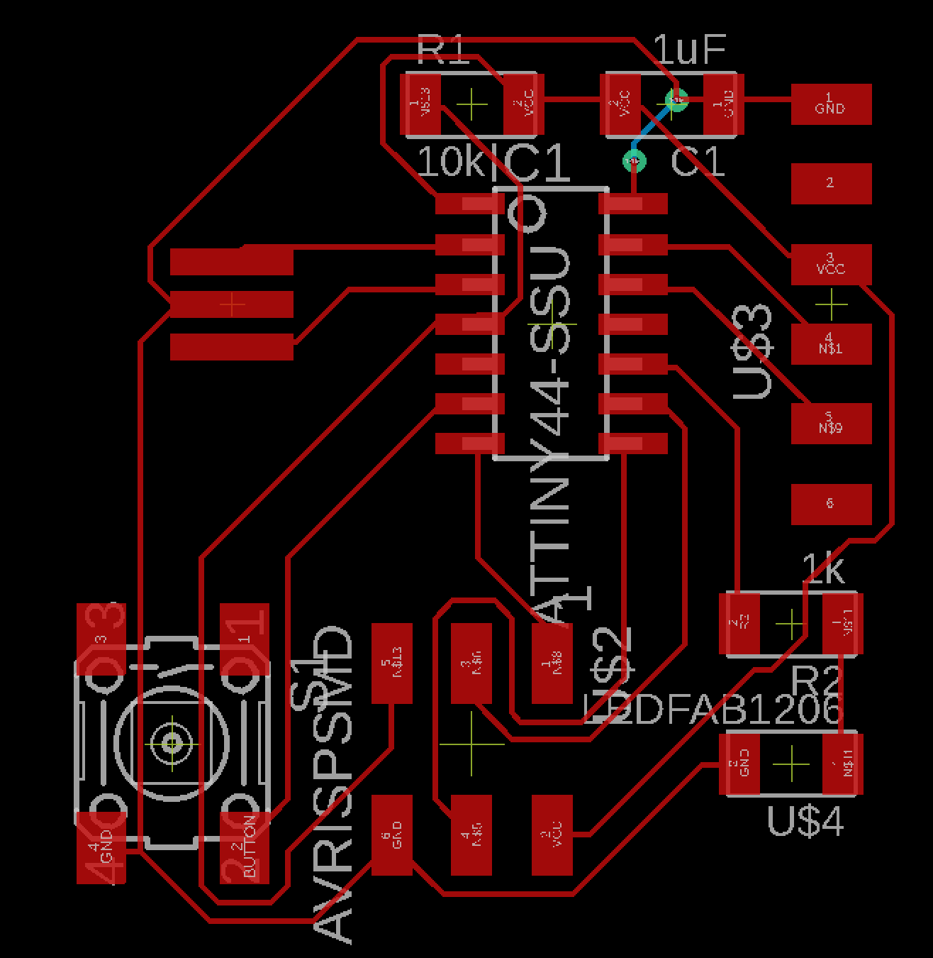
Routing the board was quite difficult. I didn’t want to have to use a two-sided board, so I had to make sure none of the traces overlapped on top. At first, I used EAGLE’s autoroute, but with the clearance we needed between traces (15.625 mm), it was seemed impossible to find a solution without vias. I then tried to route everything by hand, several times, but that just turned out to be time-consuming and I’d still back myself into a corner everytime. Finally, after 5 or 6 hours (no lie) of trying, I discovered the strategy is to just space the components out farther apart, use autoroute, check for the crossing traces and fix by hand, then compact everything down as much as possible.
Time to start milling, which we covered in week 3. Apart from a bug which causes EAGLE on macbooks to export images with twice the intended dpi, cauing my first cut to be twice as big, this part went smoothly. I stuffed my board and eagerly tried to load the program onto it.
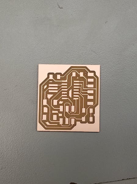
… And discover that I had mistankenly routed MISO to MOSI and MOSI to MISO, when MISO was supposed to go to MISO and MOSI was supposed to go to MOSI. Heartbreaking. Tis a lesson in labeling my wires instead of connecting them, I guess.
By the time I discovered I had to mill a new board, the queue for the main mill (SRM-20) had grown quite a bit, with everyone coming in to complete the assigment last-minute. So I turned instead to the other mill (literally, The Other Mill), which doesn’t run off of mods and has it’s very own warm-up and probing routine.
Milling with the other mill doesn’t go as smoothly. I have to try several times before I got a version I could work with, and even then, there were problems. The mill didn’t go deep enough in parts of the board, leaving copper between traces, so I had to go in with a razor blade and cut those out. The mill also left burrs along the cuts, which makes for a much messier board. I think the settings had the endmill travel too fast.
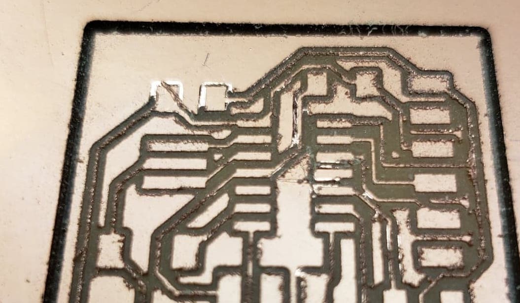
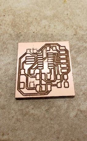
I stuff this board quickly (by now, I’m getting quite used to using the soldering iron). I go to program it, and discover there’s a short between VCC and GND. Turns out, a rather long burr of copper had connected the two. I remove it, and the program loads successfully, and finally, finally, I’m done.
I can confidently say this has been our busiest week yet, but next week is supposed to be quite crazy, so yay.
Speaker LEDs
So, in freshman year I made these speakers that had LEDs that pulsed to the bass of the music. Everything was breadboarded together quite jankily, but it worked. Until that summer, when it broke. I fixed it, but it broke again a few weeks later. I didn’t bother revisiting it until now.
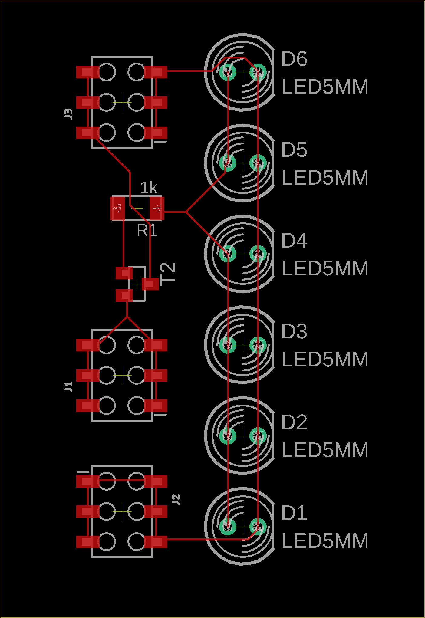
The circuitry is quite simple. I drew up a board and milled it. Since these boards have throughholes for the 5mm LEDs, I had to use the other mill. I used 6 pin headers and ribbon cables to attach to external wires.
I wasn’t able to finish it this week, but I’ll update this site when I do.
Files
hello-world-outline.png
hello-world-traces.png
echo-hello-world.c
Makefile/a>