Week 10 - Output Devices
This week, I wanted to control a vibration motor, the type they use in cell phones. This could be useful for haptic feedback in my final project if I wanted to incorporate it.
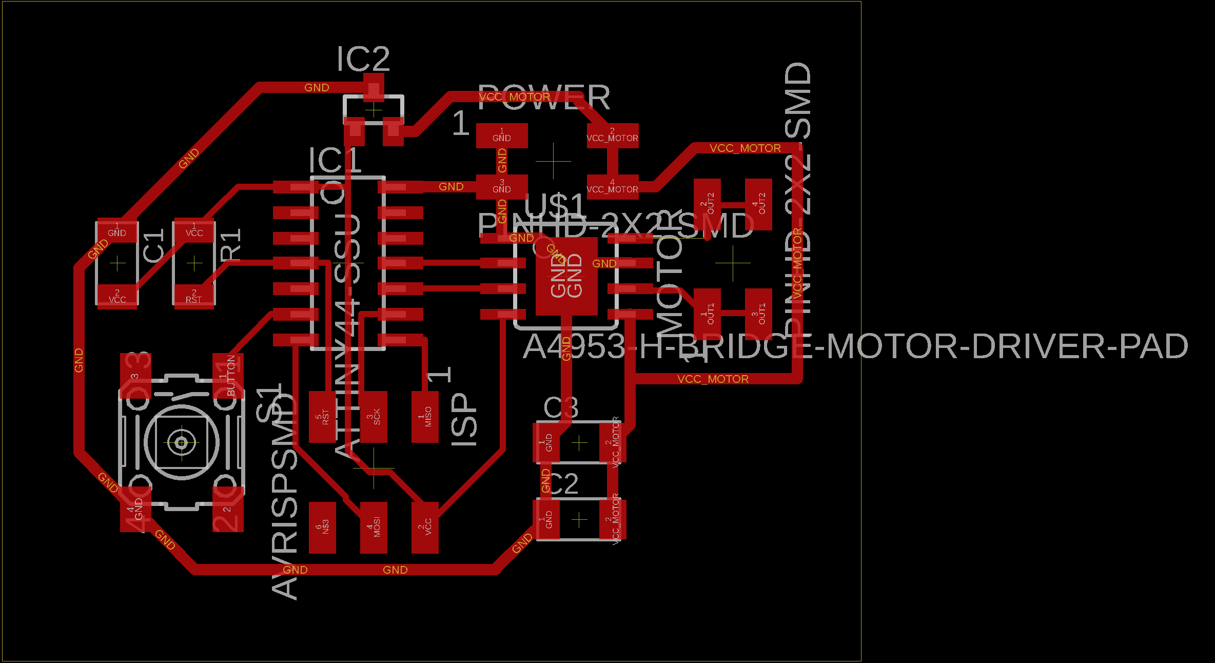
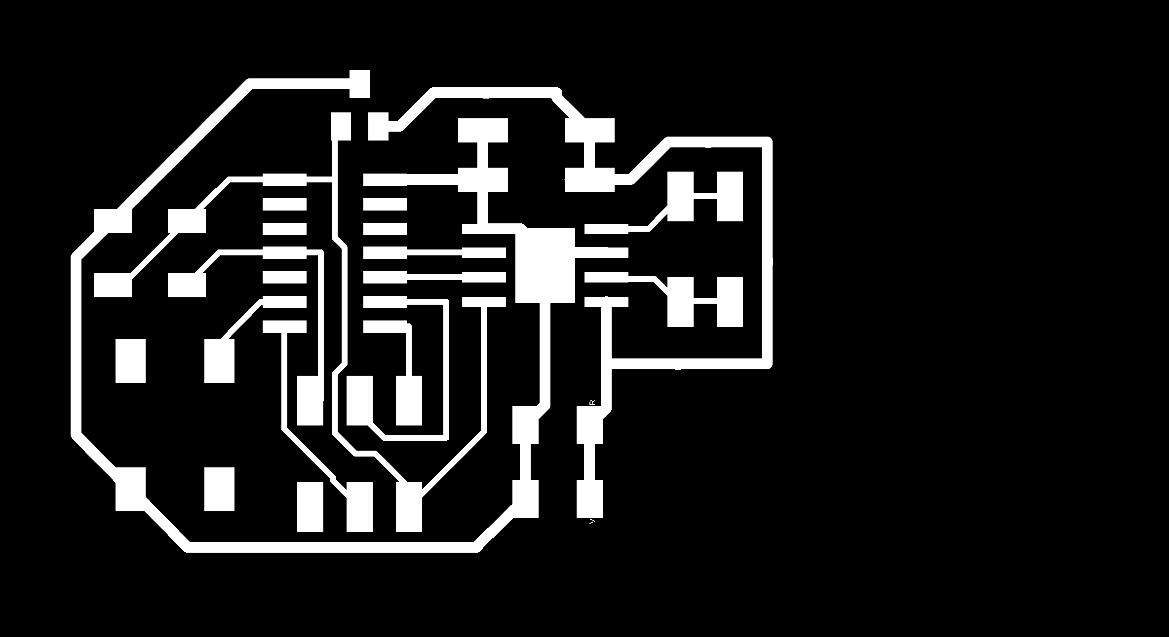
I started with designing my board, which basically consisted of taking Neil’s DC motor board and adding a button. The only difference was the power supply; Neil’s motor took 9V, the vibration motor takes 3V.
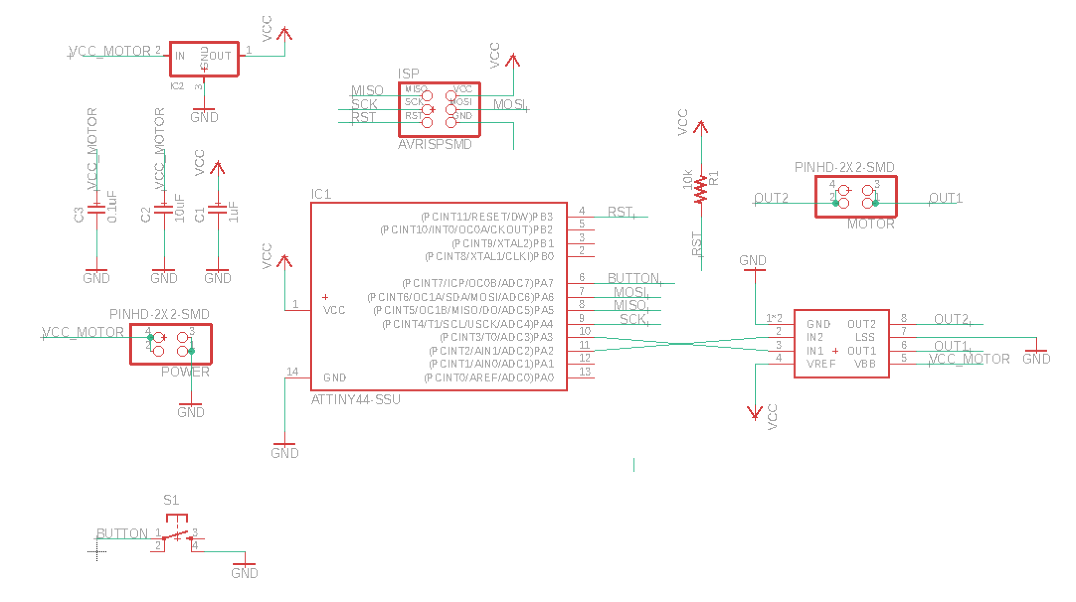
I fabricate the board, load Neil’s sample code where the motor just alternates at different speeds, plug everything into a 3.3V power supply… and nothing works. I grab a multimeter and quickly determine that the problem is centered around the h-bridge. The two input pins to the h-brige were giving expected values, but the output pins were not. The voltage drop across the pins was negligible, which means no current was flowing, which means the motor would not work.
After a few hours of debugging, Ben finally read through the datasheet and discovered the h-bridge required a minimum voltage of 8V to function, and I was only supplying 3.3V. This meant I needed to change my overall power supply to a 9V battery and needed a way to bring 9V down to 3V for the motor. I also needed the current through the motor to be around 75mA, according to specs.
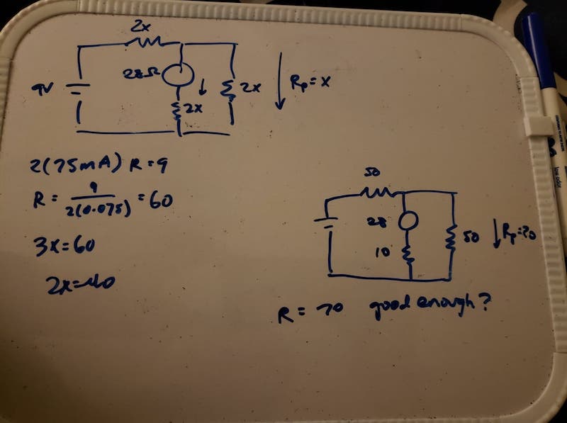
I ended up using two 43Ω resistors and one 12Ω resistor, figuring the values were close enough.
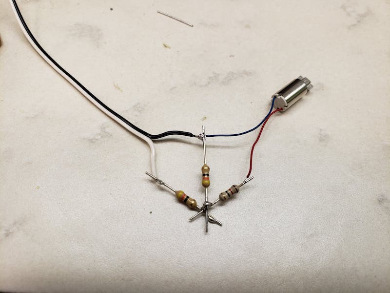
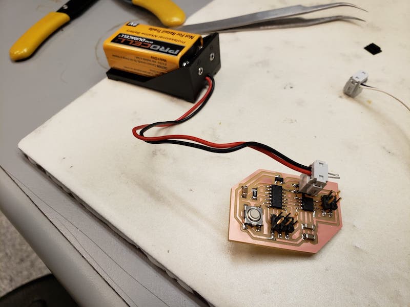
What a lovely solder job. Great for prototyping.
I also replaced Neil’s code with my own, that rotates the motor when the button is pressed.
while (1) {
	if(!pin_test(button_pins, button_pin)) {
	  clear(bridge_port, IN1);
	  set(bridge_port, IN2);
	  for (count = 0; count < 100; ++count) {
	    set(bridge_port, IN2);
	    on_delay();
	    clear(bridge_port, IN2);
	    slow_off_delay();
	  }
	} else {
	  clear(bridge_port, IN1);
	  clear(bridge_port, IN2);
	  slow_off_delay();
	}
}