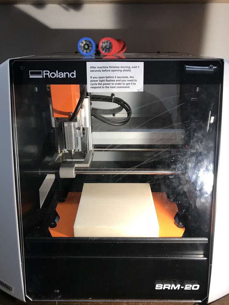
The SRM-20 used to mill my circuit boards
Assignment: make an in-circuit programmer by milling the PCB, check if you can program it, then optionally try other PCB processes.
Goal: Create the FabTinyISP according to Brian's FabTinyISP Guide.
Roland SRM-20
The project for this week was to build an AVR ISP programmer board which can be used to program future AVR circuits I'll be creating. My previous experience with electronics and milled circuit boards is relatively minimal (I don't recall if I've soldered anything since college, or maybe high school), though thankfully we were given a very, very helpful guide to direct us through the process of milling and soldering.
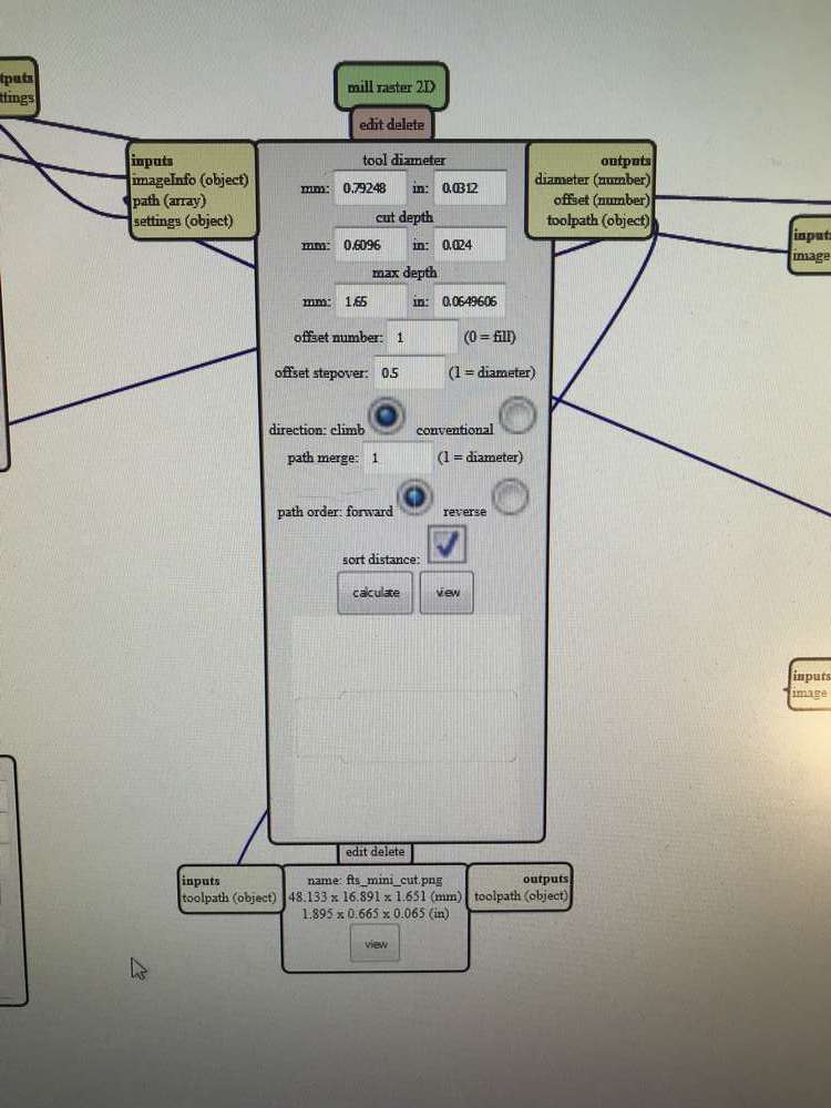
Milling the circuit board was relatively straight forward, and the pre-designed circuit boards allowed me to focus on machine setup and the production process, which I've outlined in the images below. I used Neil's Mods framework (linked above) as the print driver for the milling machine in this project.
Hover over each image for a description of that stage of the process, and click each image for a larger view.
The SRM-20 used to mill my circuit boards
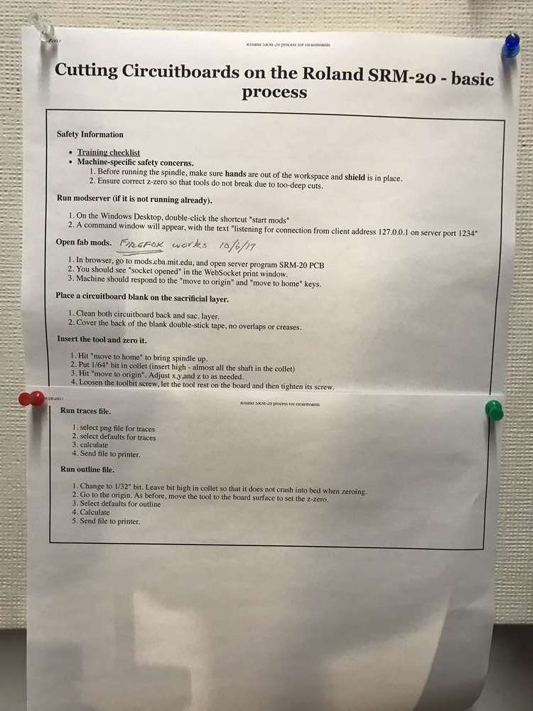
The handy guide for using the Harvard shop's SRM-20
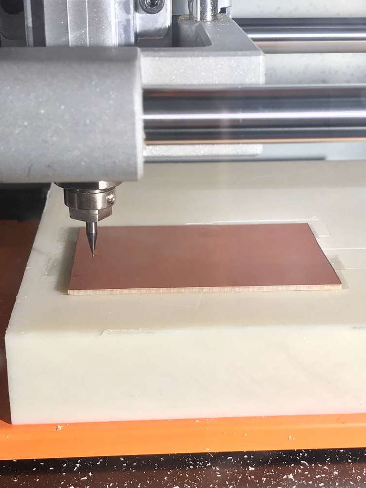
It all starts with a blank copper board
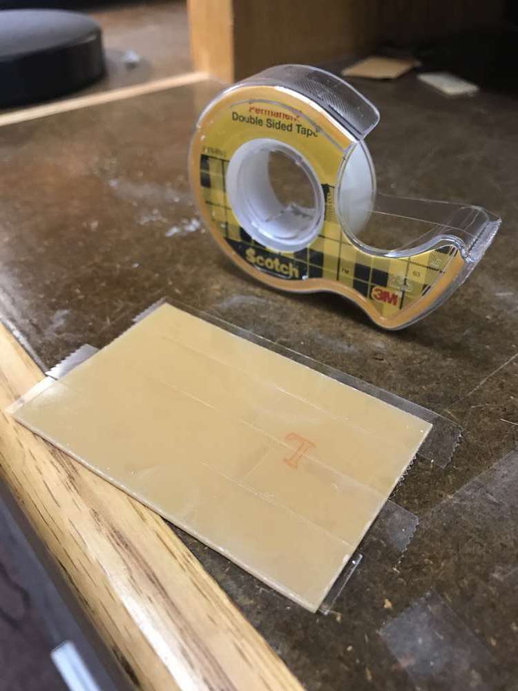
I covered the underside of the copper blank with strips of single-layer double-sided tape to prevent the board from shifting while being milled
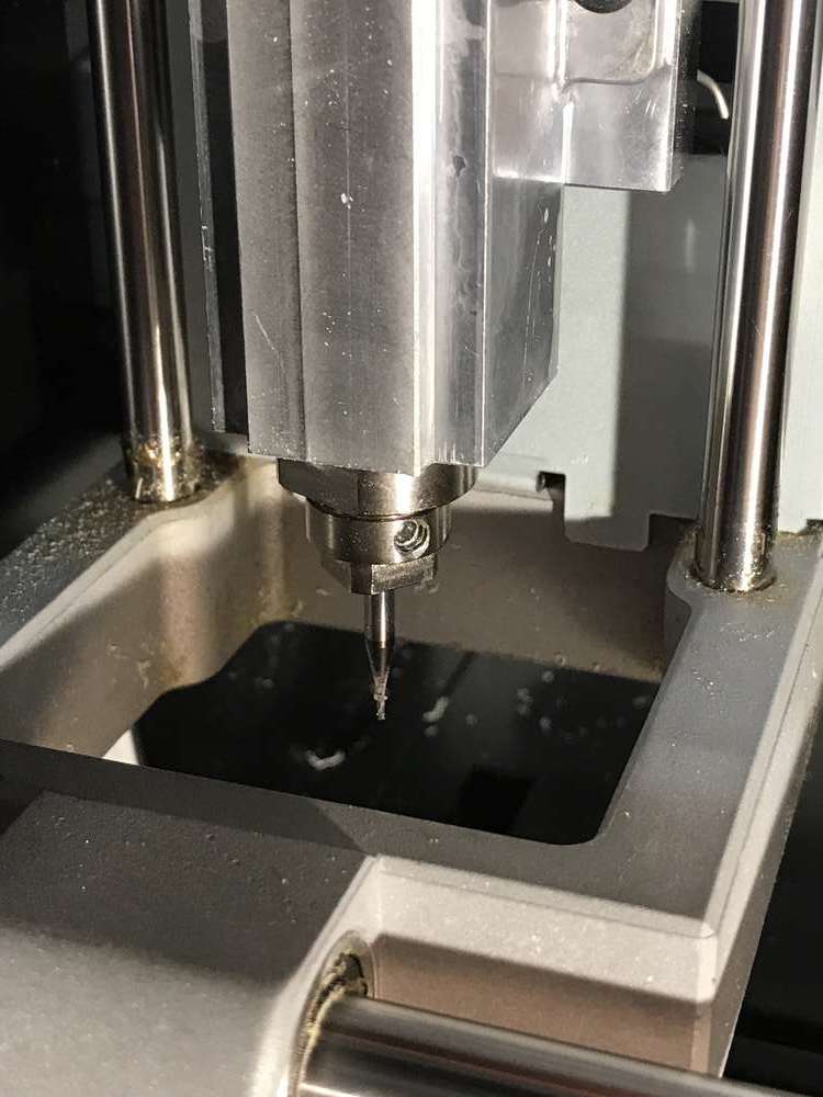
The loaded 1/32" end mill. This end mill needed to be swapped out for the 1/64" in order to mill the traces.
Adjusting the home position of the mill to the lower left corner of the blank board
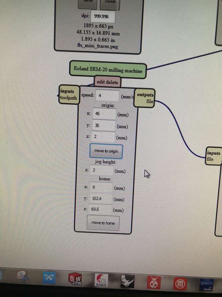
The settings used for the initial home position. I took note of two different home positions in order to mill two boards from the same blank
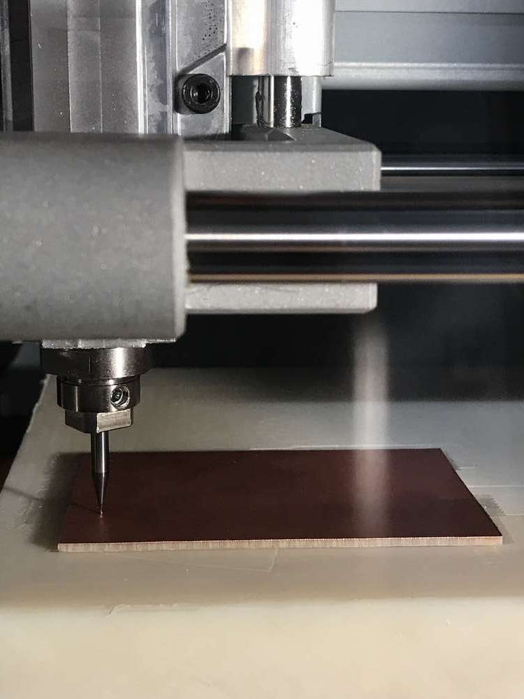
Lowering the end mill so that it just touches the top of the board
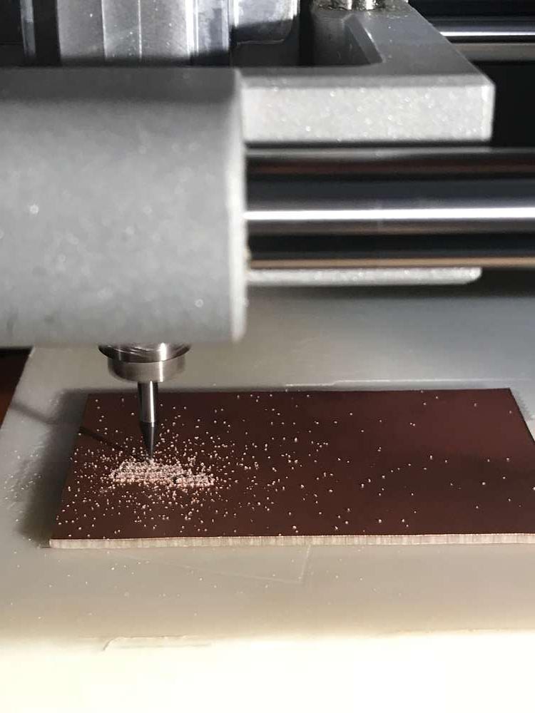
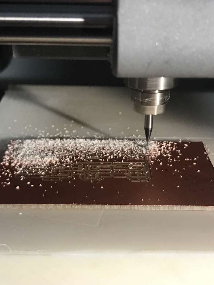
Starting to mill the traces
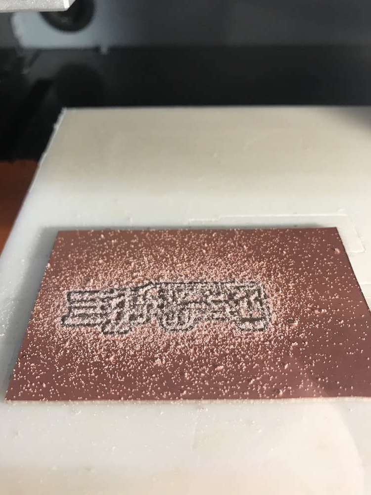
The traces of the first board are milled
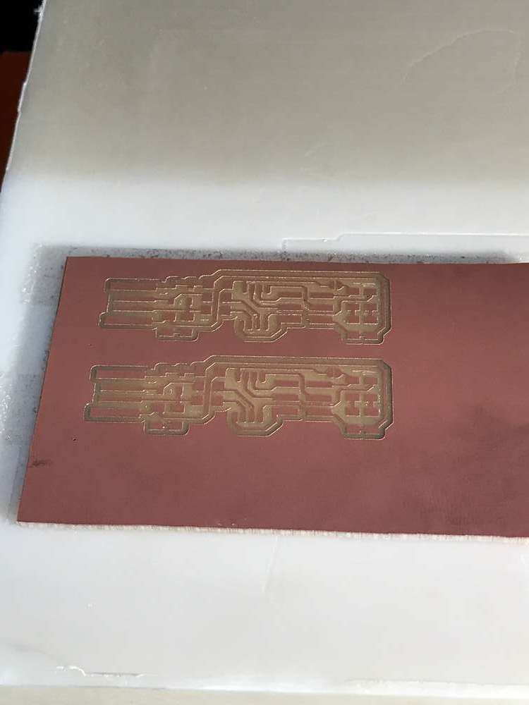
The traces of both boards have been milled and cleaned
After the traces were milled, I adjusted settings for the 1/32" end mill to mill the outline cutout of the boards
Cutting out the outline of the boards. The nearby shop-vac came in handy to clean up all the debris
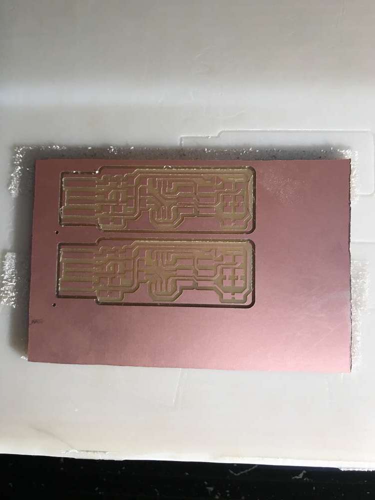
The milled traces are now separate boards in their own right
Though initially a bit overwhelming, the electronics schematic proved to be everything I needed. It answered questions I hadn't realized I would have, such as the orientation of diodes. This was my first time soldering surface-mount components to a board, though the process was pretty much the same as soldering anything - use a little bit of solder to get things started, and heat both component ends to ensure a solid connection. I got into a zone while soldering, and unfortunately neglected to pause mid-way to photograph my process. Nevertheless, here are some images from the beginning and the end.
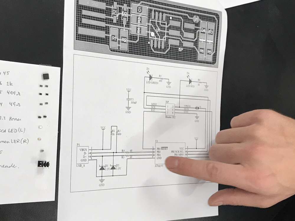
Following the schematic for the FabTinyISP. My fellow classmates helped me identify the necessary electrical components
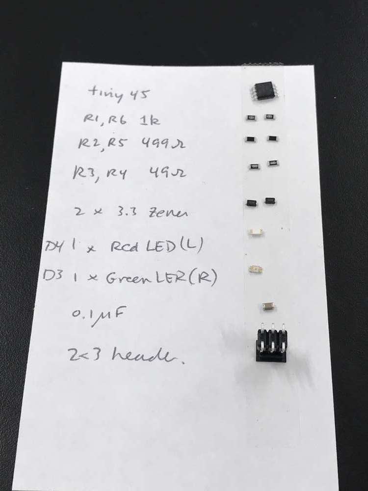
A reference of needed parts. Placing a strip of double-sided tape on an index card to keep track of electrical components worked surprisingly well to gather, organize, and store what was needed
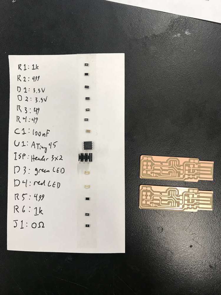
All the necessary components along with my milled boards
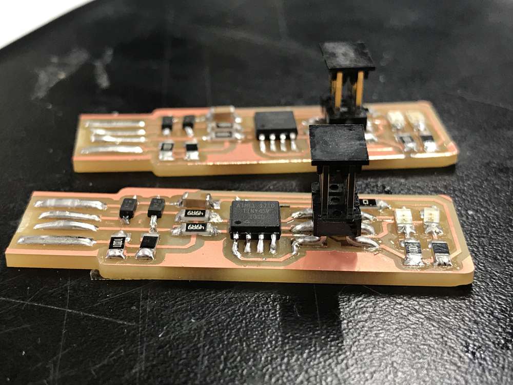
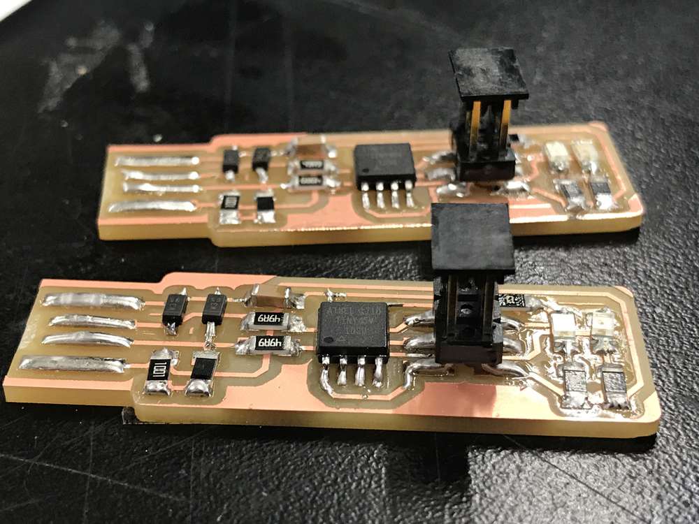
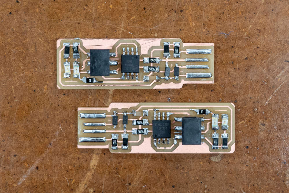
The completed, soldered boards
The boards seemed to come out well. Following the guide, I was able to install the programming environment on my laptop and tried to program my board before I realized I would need an existing programmer board to complete the process, which I didn't have on hand at the time. Nevertheless, my board did light red when plugged into my USB port, which is an achievement in and of itself. I'll post an update once my boards are programmed and functional.