Week 2: Electronics Production
PCB Milling and Soldering
PCB Milling
1. Introduction
The first thing we had to do this week was learn how to use the PCB mill to cut out copper connections. We already had a premade design by the class called the FabTinyStar. This is an ISP programmer that we will use in the future to program other boards. The set up was relatively easy, as first I just had to cover the back of the copper plate with double-sided tape and I put it on the sacrificial block inside the Roland SRM-20 PCB mill. For all the settings on the PCB mill, I just used Professor Neil's mod for the Roland SRM-20 mill.
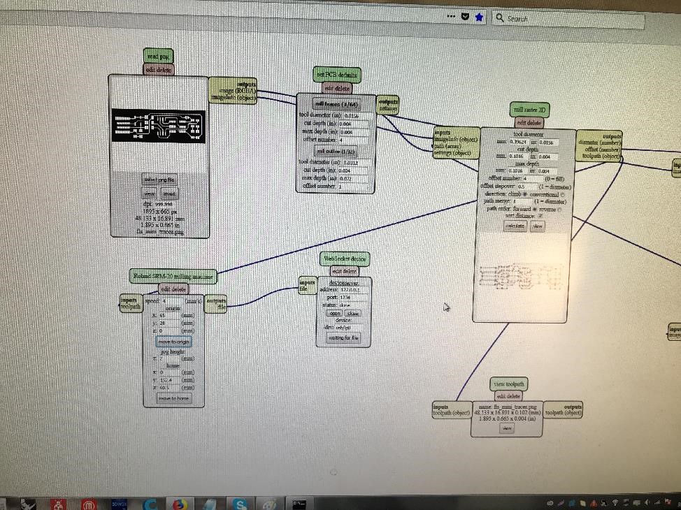
Figure 1. Using Neil's mod for the Roland SRM-20 PCB Mill.
Then, I had to set the origin point of the mill so I moved the x, y, and z-axis of the drill to the copper plate. Once I had my origin point and I lowered the z-axis to 0 mm over the copper, I had to manually unscrew the endmill and lower it onto the copper. I used a 1/64 end mill for the first mill cut to cut out the copper circuits.
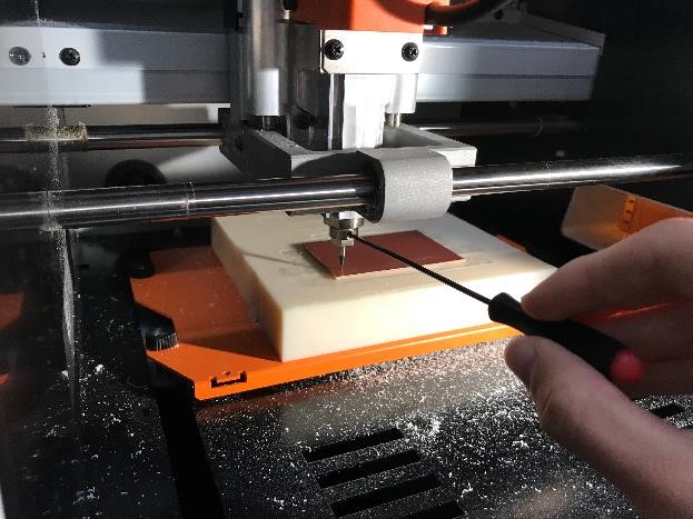
Figure 2. Using the screwdriver to make sure that the endmill is on the copper plate.
2. Milling PCB #1
After setting up the mill I started the actual milling process, which didn't turn out quite well in the beginning. As I was milling, there wasn't enough copper dust coming out of the cut so I realized that it wasn't cutting deep enough.
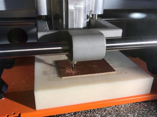
Figure 3. Oh no the PCB mill wasn't cutting deep enough.
I stopped the cutting and made sure that the drill was correctly pressing onto the copper plate and when I ran it again it was working perfectly! After the milling the PCB came out pretty nice.
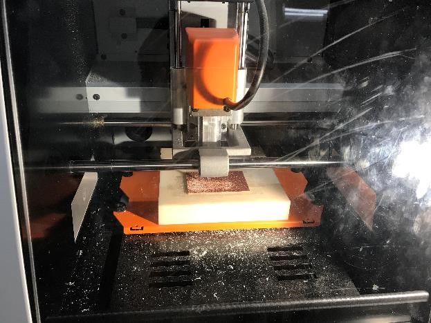
Figure 4. As you can see in the picture, there is way more copper dust in here than in the previous picture (never knew that more dust would be a good thing, I should tell my mom).
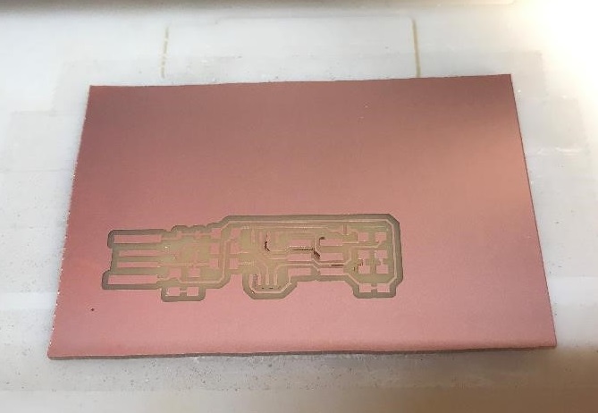
Figure 5. Finished version of the first PCB cut.
3. Milling PCB #2 (aka epic fail)
After cutting the first PCB, I moved the origin of the drill to a different spot and proceeded to cut my second PCB. I thought this would be easy but after the cutting finished I noticed that there was a big part of copper that wasn't cut completely.
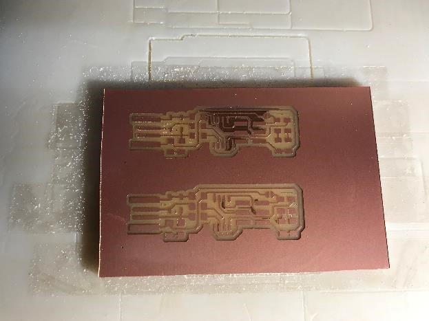
Figure 6. The top PCB has a copper part that will probably result in a short circuit, which is not what I want.
I tried doing the same cut once more on the PCB to try to cut out the leftover copper to still no success. After asking for help I decided to increase the max depth of the drill from the default of 0.1016 mm to 0.11 mm (shoutout to Victoria Shen). After running this cut, I thought I would be fine but the leftover copper was still there!!! I was honestly about to give up on that cut but then I decided that I would give this PCB board one more chance so I changed the max depth to 0.20 mm and the cut depth from 0.1016 mm to 0.13 mm (I know, I'm such a rebel for pulling these risky moves, not really). Magically, the 3rd time was the charm and the top PCB came out better than the first try!
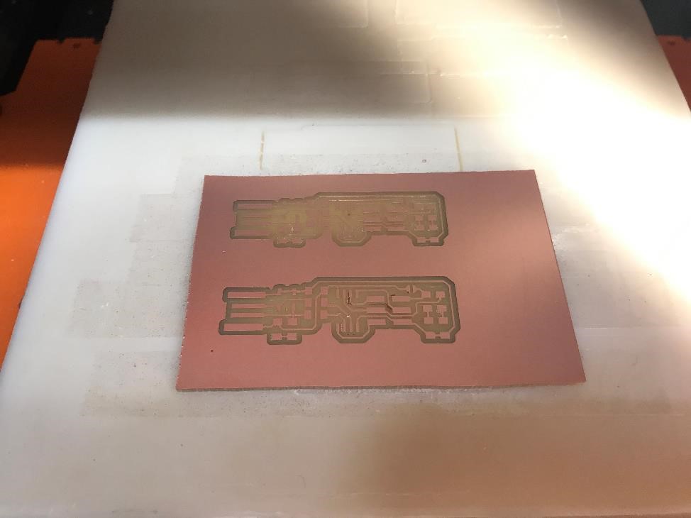
Figure 7. Finally, I'm finished with the circuit cutting of both PCBs!
4. Milling outlines of both PCBs (aka more epic fails incoming)
I thought I was done taking losses on the PCB mill after taking longer than usual on the top PCB, so I just proceeded to replace the 1/64 in endmill to a 1/32 in one for the outline of the PCB. Then, after changing the settings on the mod, I press the start button. I looked to the PCB mill to see it cutting and then I noticed something weird... it was cutting in the previous path of the circuit... At that moment I realized that I forgot to change the path of the circuit to the outline version and thus it started going over the previous cut with a thicker endmill. I quickly switched it off and put the right PNG file in.
Then, after double-checking that all of my settings were right, I set the mill to cut out the outline of the PCB. Once it was finished though I noticed another error. The bottom of the cut had a bunch of serrated copper that didn't quite look right. I was trying to see what went wrong, and saw that the endmill didn't look right. The endmill had actually partially broken off when I tried to do the outline of the circuit cut with the 1/32.
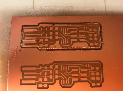
Figure 8. Here you can see my first mistake where the drill dug in too deep so there is white copper dust stuck there and also the serrated edge of the top PCB #Lsonly.
After these mistakes (lesson learned: Ryan is not very good at PCB milling), I did the same thing for the bottom PCB and it actually went really smooth and came out alright! So I guess it was just the top PCB that kept giving me problems throughout this process.
5. Finished Product!
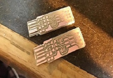
Figure 9. The finished PCBs after milling! At least one of the PCBs looks nice.
Soldering
1. Introduction
For the soldering part, we were supposed to solder the components that were on Brian's page onto our ISP. Before I started, I had to make sure that my PCB's were working correctly so I used a rag to brush the PCB and made sure that it was shiny enough so that I could solder onto it. Then, in my milling process, I messed up multiple times (refer to above portion for list of failures), so I had to make sure that there were no short circuits. Rob told me that I could use the multimeter with the sound setting to check if two copper parts were connected. Thanks to this, I could check if two parts that weren't meant to be were connected and then I scraped these parts off with an x-acto knife.
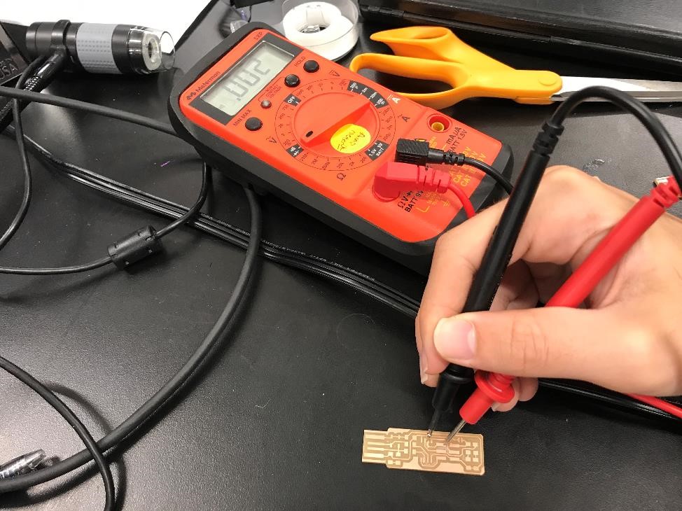
Figure 10. Testing the PCB to check for short circuits and copper connections.
After checking these connections, I proceeded to grab all the components I needed for the soldering. It was really easy since all the parts where on the website and they were labeled yellow in the lab. I didn't even realize that we were going to use such small parts because when I soldered before we used through holes and the components had wires. The components were so small I was scared that I was gonna mess up!
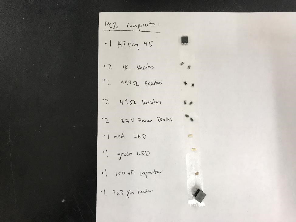
Figure 11. Collected all the parts to solder. The components are so small!
2. Actually Soldering
I enjoyed the soldering part of this week better than the milling part since I actually found it relaxing (I just realized how nerdy this sounds but it's fine). I started by practicing with the resistors since I didn't want to mess up the ATtiny 45. The soldering process was pretty straightforward since I just needed to apply the solder onto the little copper area where the component would go, move the component to its place and anchor it to the place by using the original solder. Then, I would properly solder all parts of the component and fix the original anchor. I did this with all the components.
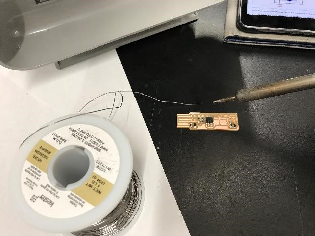
Figure 12. Soldering the components.
The ATtiny 45 was the hardest part since there were 8 "legs" and they were all close together so I was trying hard to apply the right amount of solder but to not short circuit anything. One time I applied too much solder on one "leg" so with Rob's suggestion, I used the copper braid to desolder and lessen the amount of solder on the part until it looked nice. It worked like magic!
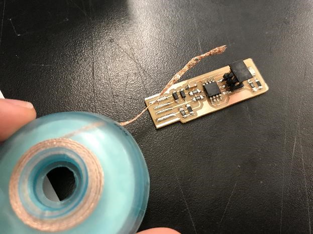
Figure 13. Using the copper braid to desolder.
3. Finished Product!
After I finished the soldering of the components, I added solder to the USB part of the PCB and connected the bridge so that I could program the PCB. After checking with Rob that everything looked good I plugged it into the computer with a USB extender (I had to add a little piece of paper under the PCB since it was too thin), then the red LED lit up! Yay it worked and it actually took me way less time than I had anticipated.
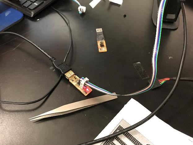
Figure 14. The PCB's LED lit up! It works!
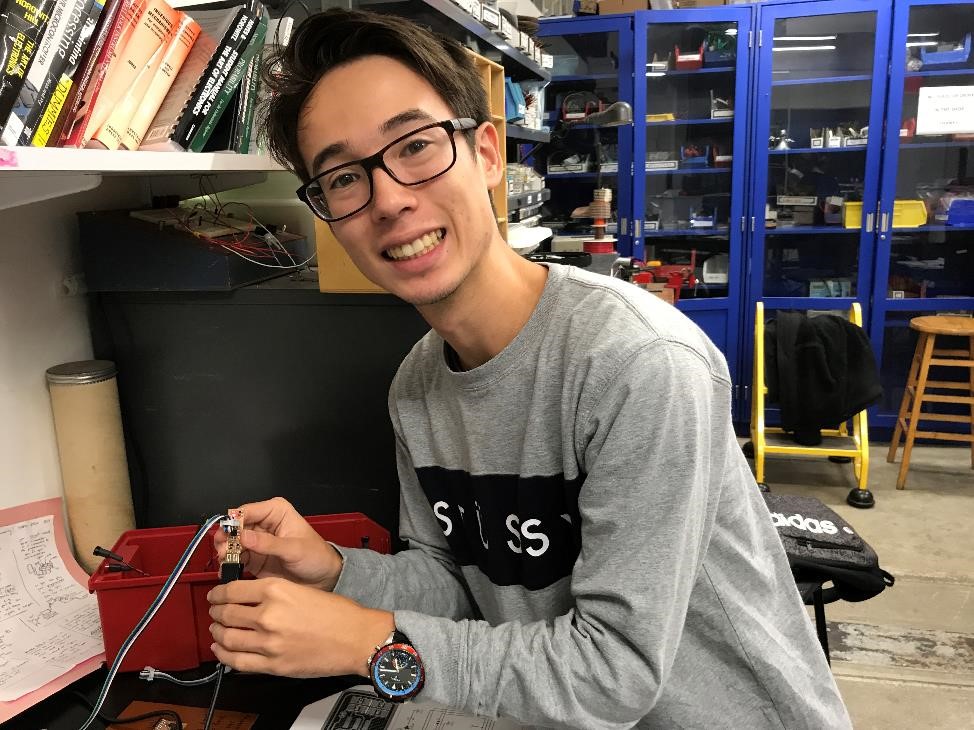
Figure 15. Picture of me with the PCB!
4. Extra: 2x3 Pin Header Connector
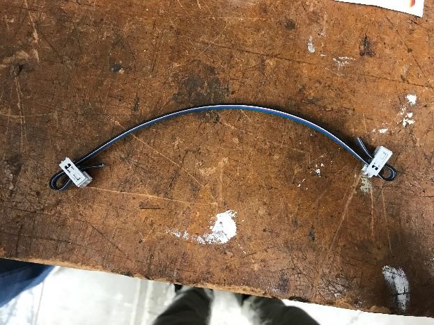
To upload the program onto the PCB I had to use a cable to connect the 2x3 Pin Header, but Rob suggested that I make my own since I'll need it in the future. To make it I had 6 connected wires and tightened a piece that would hold the cable in place.
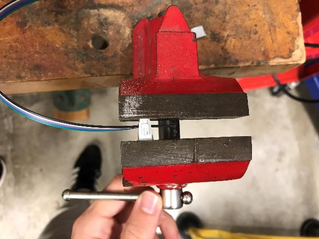
Figure 16. Tightening the 2x3 Pin Header Connector Cable.
Then I would add an extra component that would allow me to slide the cable and repeated this for the other side, and voila I had my 2x3 Pin Header Connector!