Week 4: Electronics Design
PCB Design: Eagle and KiCad
PCB Design
1. Introduction
This week we were supposed to expand beyond what we did in Week 2 and actually design the PCBs that we would mill and solder. We were supposed to redesign a PCB called the "echo hello-world" board. We were supposed to add 2 components (a button and an LED) to the current design and do the rest of the work around it. We had 2 software options and I ended up choosing KiCad first (because of its compaitibility with Solidworks), however I had to end up using both softwares because of bugs.
2. KiCad
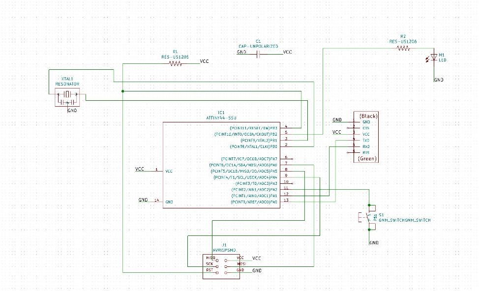
Figure 1. Schematic of my finished PCB on KiCad.
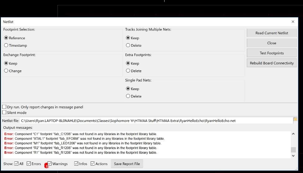
Figure 2. Error on KiCad importing the fab class libraries.
3. Eagle
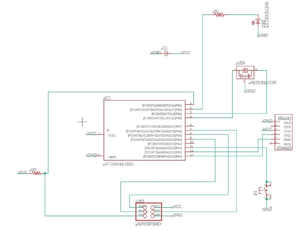
Figure 3. Schematic of my finished PCB on Eagle. (Surprise! Looks almost the same as the KiCad version).
After futilely not being able to import the fab library correctly into KiCad, I decided to try ty another PCB Design software that most other people in class had worked on (Eagle by Autodesk)
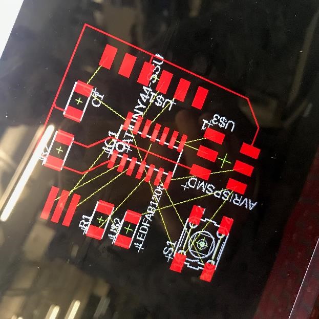
Figure 4. Layout of my PCB on Eagle after using ratsnest.
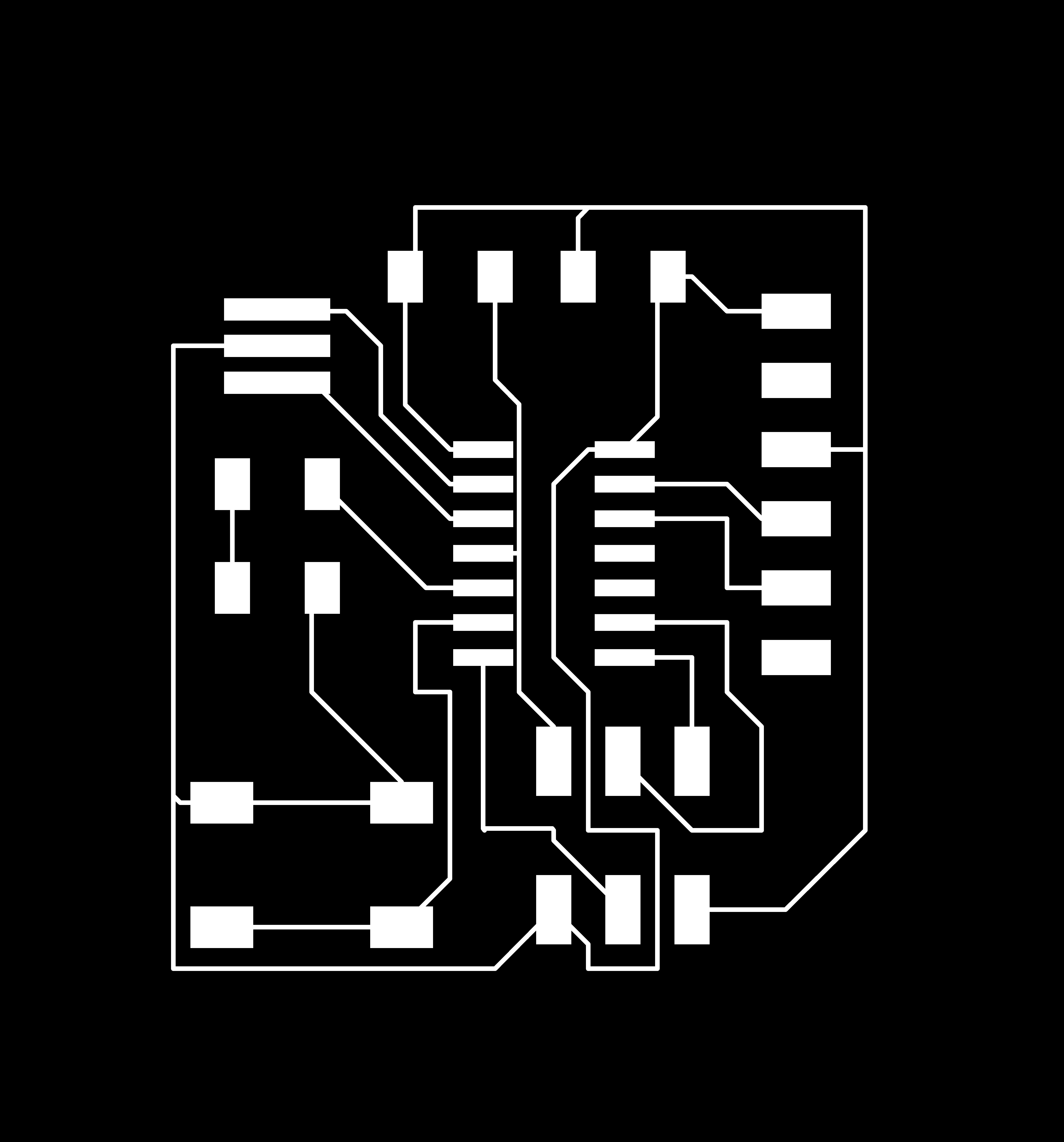
Figure 5. Traces of my PCB.

Figure 6. Outline of my PCB.
4. PCB Milling (again)

Figure 7. Opening up mods (throwback to last week).
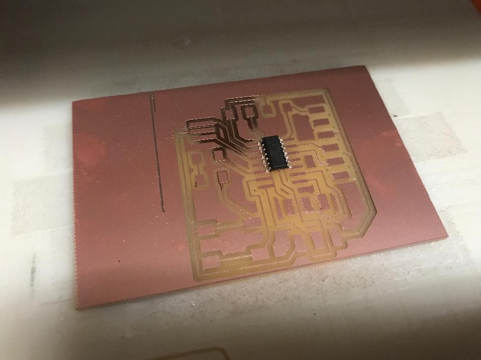
Figure 8. Of course my PCB had to come out with some sort of error, just like last week...
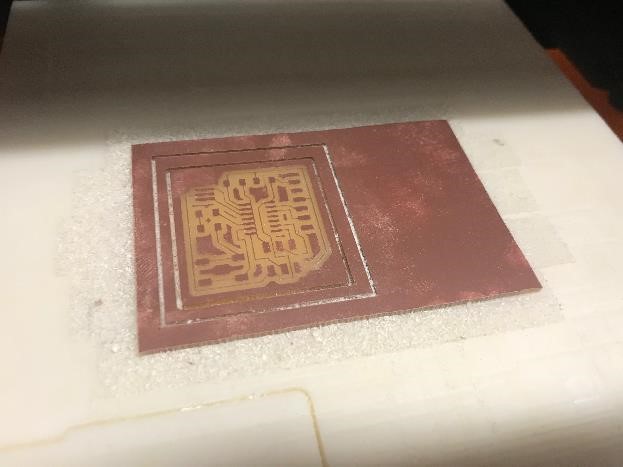
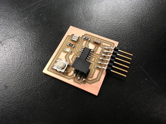
Figure 9. Finished with milling my PCB!.
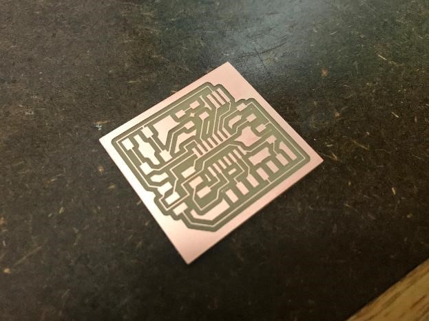
Figure 10. Finished PCB without soldering.
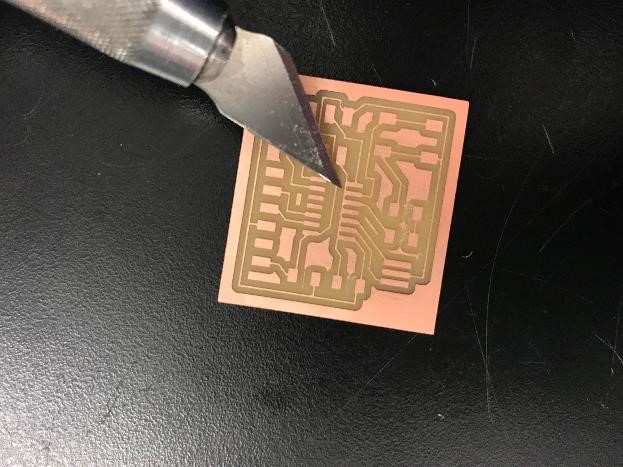
Figure 11: Using a knife to severe some connections.
5. PCB Soldering (again)
6. Finished Product