How To Make Almost Anything Neil Gershenfeld

MIT Center For Bits And Atoms
FINAL PROJECT
Fab labs share an evolving inventory of core capabilities to make (almost) anything, allowing people and projects to be shared. These are my projects.
Proposal -
Bluetooth Helmet
09.05.18
For my final project, I propose a motorcycle helmet with embedded wireless speakers which pair with a mobile device via Bluetooth, transmitting navigational details from Google Maps, or other GPS sofftware, into the ears of the rider. Additionally, if not over-ambitious, I would propose a simple AR feature, somehow projecting details such as current speed onto the transparent visor protecting the rider's eyes. If this is indeed feasible, then perhaps it would be possible to indicate when a turn is called for via the Google Maps API, projecting a small arrow corresponding to the direction of the turn.
The rendering below is an .svg file created in Adobe Illustrator showing a cross section of the helmet. It reveals the visor, the outer shell, the inner padding for impact and one final layer of softer padding for the rider's head. Lastly, in the bottom portion of the back of the helmet there is a space for circuitry. The speakers are not visible in this cross section but will be added in following visualizations.
An iteration of this idea does already exist for pre-order at time of writing; however, I would like to see if I can build my own version at a fraction of the cost. More than likely, my version will not be as robust, however, it will be a good final project since it will bring together many different aspects of the fabrication processes we have been learning in this class.
UPDATE -
Pivot to ADXL Brake light
(for helmet, or really anything)
12.03.18
The autonomous brake light is complete! Files here.
- What does it do?
- Who's done what beforehand?
- What did you design?
- What materials and components were used?
- Copper coated bakelite boards for milling PCB’s
- Attiny45 microchip - $1.23
- ADXL343 accelerometer - $2.71
- 10K Resistors (x3) - $0.01 each
- Capacitors - 0.1uF $0.12 and 1uF $0.07
- Water Clear 5mm LEDs (x3) - $0.01
- N-channel Mosfet - $1.13
- 3.3v regulator - $0.32
- 6 pin FTDI header - ?
- 2x3 header - $0.60
- Wires - n/a minimal usage
- Heat-shrink tubing - n/a minimal usage
- 3D printed PLA on Makerbot, black for housing and transparent for lid
- Switch - ?
- Button - SWITCH TACT SMD W-GND 160GF - $0.74
- 3.7V Lipo battery - 3.7v lipo battery - $11.13
- Programmed with my FabISP
- Where did they come from?
- How much did they cost?
- What parts and systems were made?
- What processes were used?
- What questions were answered?
- How was it evaluated?
- What are the implications?
My final project is what I would call an autonomous brake light, in the sense that it is not connected to any braking mechanism but rather employs an accelerometer for detecting changes in acceleration. In the case of my device, only the values from the Z axis are monitored, due to the orientation of the board within the housing. When the Z axis drops below a given threshold, signaling deceleration, the LEDs are turned to maximum brightness, otherwise they remain illuminated but at a much dimmer frequency. The Z axis threshold can be reset relative to a new baseline value at any given moment by holding down the button on the main board for at least one second. When the button is pressed accordingly, the LEDs will rapidly blink twice to indicate a successful reset. Finally, the brake light is housed in a 3D printed case with a sliding, translucent lid and a sliding mount that allows it to be easily attached to almost anything. A switch on the exterior of the light allows users to power the device on and off easily, without opening the lid.
The dimming of the LEDs is achieved through what is called Pulse Width Modulation, or PWM. PWM allows us to control, with a precise degree of resolution, how much time a signal is high in an analog fashion. While the signal can only be high (V) or low (ground) at any given instant, we can change the proportion of time the signal is high compared to when it is low over a consistent time interval. This method is commonly used to modulate the brightness of LEDs. By flickering an LED on and off at speeds faster that the human eye can detect, we can create the effect of dimming the light in proportion to the amount of time that the light is on/off during a given PWM cycle.
In my research, I came across some conflicting information concerning whether such devices are active vs. passive. One issue is that the active/passive dichotomy is used differently in different contexts, like the automobile industry, the engineering field, and the nuclear power sector to name a few. Suffice to say that in the auto industry in the U.S. “active safety” is increasingly being used to refer to systems that rely on input devices to provide information on the state of the vehicle to both avoid and minimise the effects of a crash. With that in mind, I would venture to classify this autonomous brake light as an active safety device.
There are several precedents for this project ranging from slick, fully-developed products already on the market, to simple arduino tutorials. An indiegogo campaign for a similar project, intended for motorcycle helmets, raised over $215K last year in 2017. Also in 2017, another HTMAA student, Inês Carmo, made a variation of this device for her final project as well, intended for use on a bicycle.
I designed almost every aspect of the project, often leveraging or reverse engineering pre-existing components. For example, I modified Niel’s ADXL343 board from input week, adding a button, a mosfet and a breakout LED board of my own design. I modified Niel’s C file for the ADXL, adding a hardware PWM and incorporating some aspects of other Arduino projects, translating their code into C, which wasn’t always easy. For the housing I was able to take several files from Thingiverse, an open-source library of files ready for 3D printing, import them into Rhino and edit and combine different components to my exact specifications. This was a painstaking process and if I was more advanced in Rhino, I would try to build the mesh from scratch as opposed to reverse engineering several files.
All of my components were readily available in the Harvard Fab Lab. Almost all of them are included in the Fab inventory
See above for individual component costs. Total cost is less that $20, more than half of which is the 3.7v battery.
As mentioned previously, my project employs an accelerometer for detecting changes in acceleration, and a break-out board for three parallel LEDs that are controlled by a single pin on the tiny45, using a mosfet so as not to pull too much power through the microcontroller. I use a hardware PWM to dim my LEDs and also have a button that triggers a special “reset” function for the Z-axis threshold. Since I am using every pin on the tiny45 it was necessary to assign the button to one of the pins being used for the timer/counter required for the PWM. This was causing the PIN to be set, however briefly, on each duty cycle of the PWM. So I programmed the button function to run only when the button has been held down for over a second. I thought this was a clever solution the problem since it economized the use of pins.
I used a 3-axis milling for my boards; electronics design in Eagle and photoshop; soldered/wired/built my own electronics; all of my microcontroller interfacing was done using my Fab TinyISP, and all of my programming was in C; designed my housing in Rhino and 3D printed it using the the makerbot, in two different filaments; my system integration and packaging includes an on/off switch, a 3.7 lipo battery and careful wiring protected with heat-shrink-wrapping; I also made a composite helmet to mount the device on, although it didn’t turn out as well as anticipated.
I learned an incredible amount over the course of the semester and especially in the effort to complete this final project. I learned a lot about programming in C, including: serial communication (and parsing it!), software and hardware PWM, calling various functions depending on how long a button is held/pressed.
I have evaluated this project based on feedback from the user-interface Neil wrote in python and provided for the ADXL. I can see the current Z value in the user interface and adjust at will using the button. I can see that my Z reset function is running correctly due the blinking of the LEDs when the button is held down for the allotted time. By noting the Z value at the time of the button press, I can move the device and watch the values go above and below the threshold. When the LEDs are dim above the threshold and bright below, then the device is working as programmed. After a lot of blood, sweat and tears it finally works perfectly!
I simplified my initial idea for a final project in an effort to ensure that my goal was attainable in the time allotted. That said, I wanted to make my simple project as difficult as it could be, for example by insisting on programming in C instead of arduino and by making my own LED board instead of buying one from Adafruit. Sometimes doing simple things the hard way can be more rewarding than doing complex things in an easy way, by leveraging powerful libraries or pre-made components. Overall, I spent a tremendous amount of time on this effort and had some very frustrating setbacks, including going through about 7-8 final boards, three different housing units and 4 different lids. In the end I am very proud of the final result, humble as it may be, and think that despite the chunkiness of the housing my system integration and packaging was very clean and well-executed.
I see many opportunities to advance this project and spiral outward into more complex iterations, like turn signals and rechargeable battery integration to name just a few.

Fig.1 Adobe Illustrator vector rendering of helmet cross-section, with a little hollow area for circuitry near the bottom
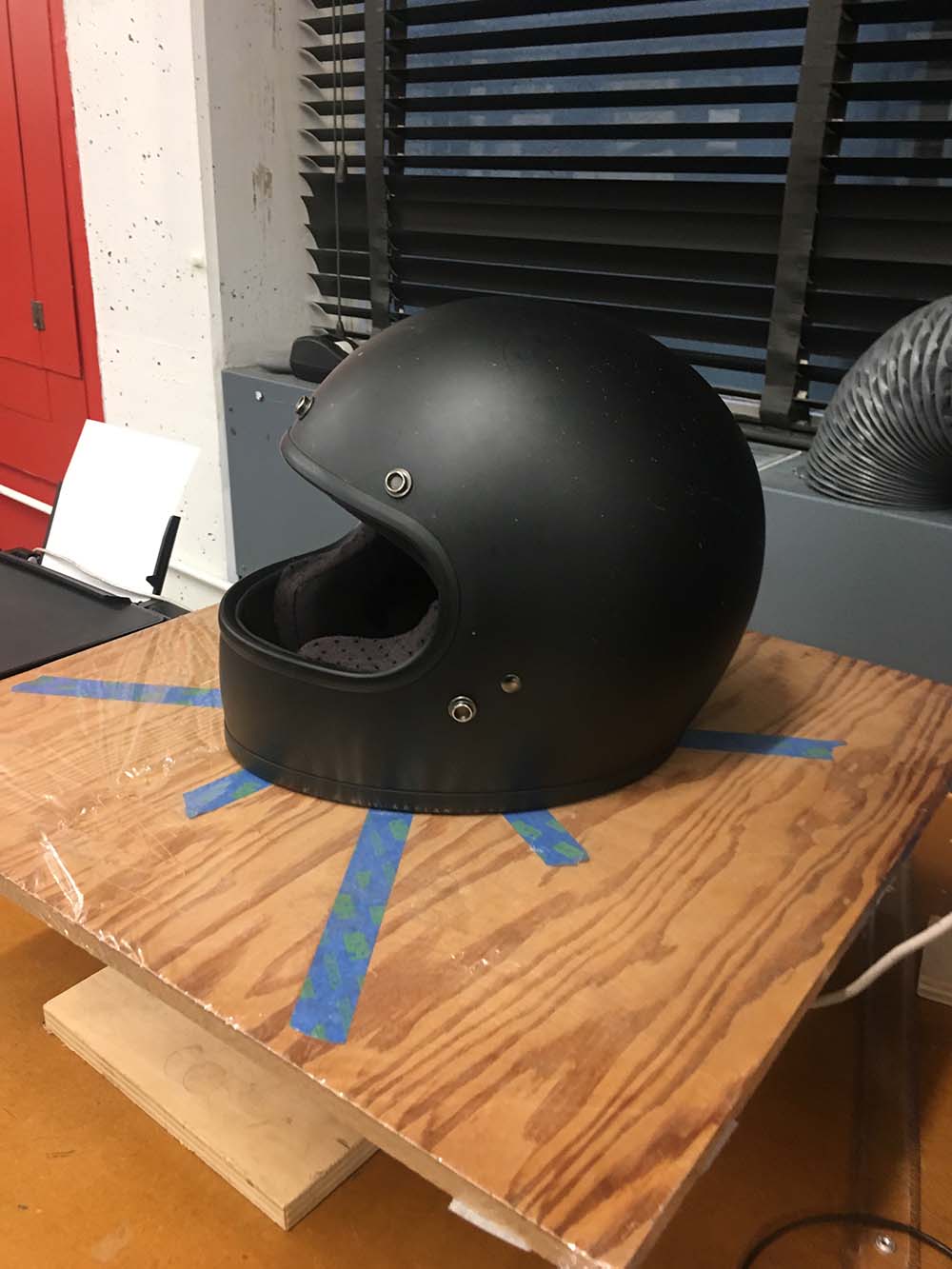
Fig.2 My Bitwell "Gringo" helmet ready for 3D scanning

Fig.3 3D Scanning the helmet
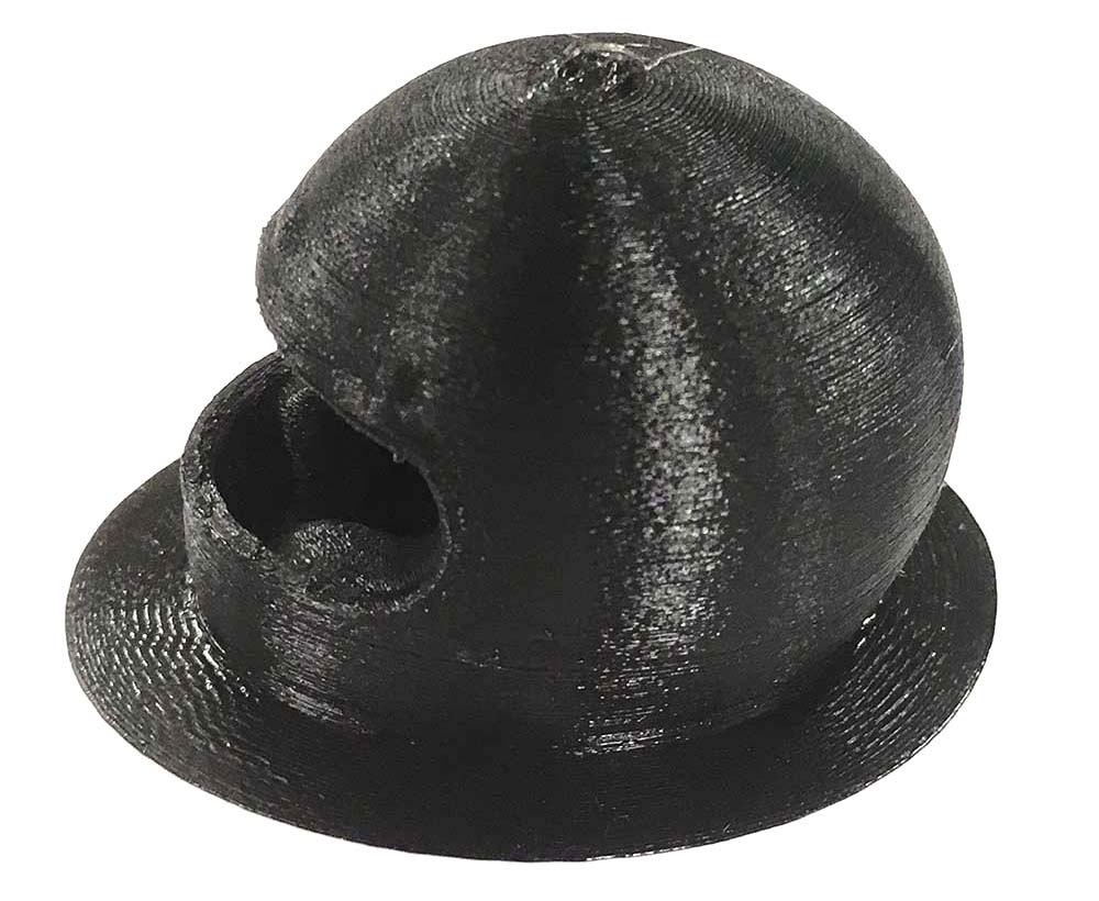
Fig.4 3D print of helmet
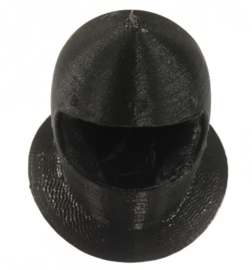
Fig.5 3D print of helmet, alternate angle
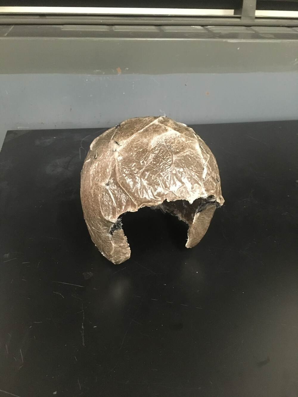
UPDATE: In week 14 I made a composite helmet. Didn't turn out great but at least I tried. Luckily my final project is no longer dependant on it.
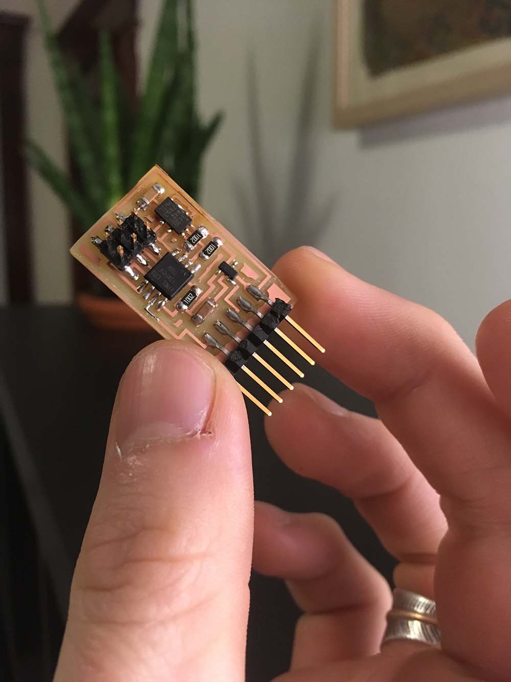
Fig.6 My accelerometer board
Fig.7 My accelerometer is working!
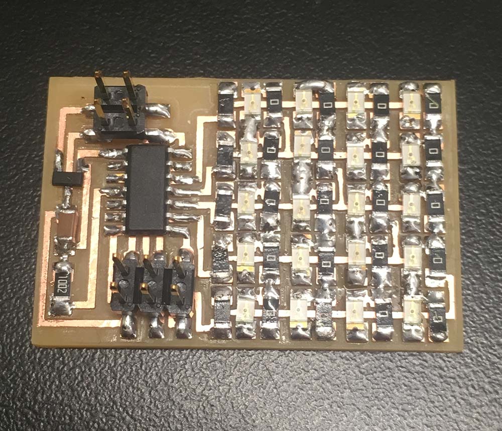
Attempt at Charlieplex board for brake light
Fig.8 Charlieplex array is shorting?
Fig.9 3D printed case for brake light, first iteration
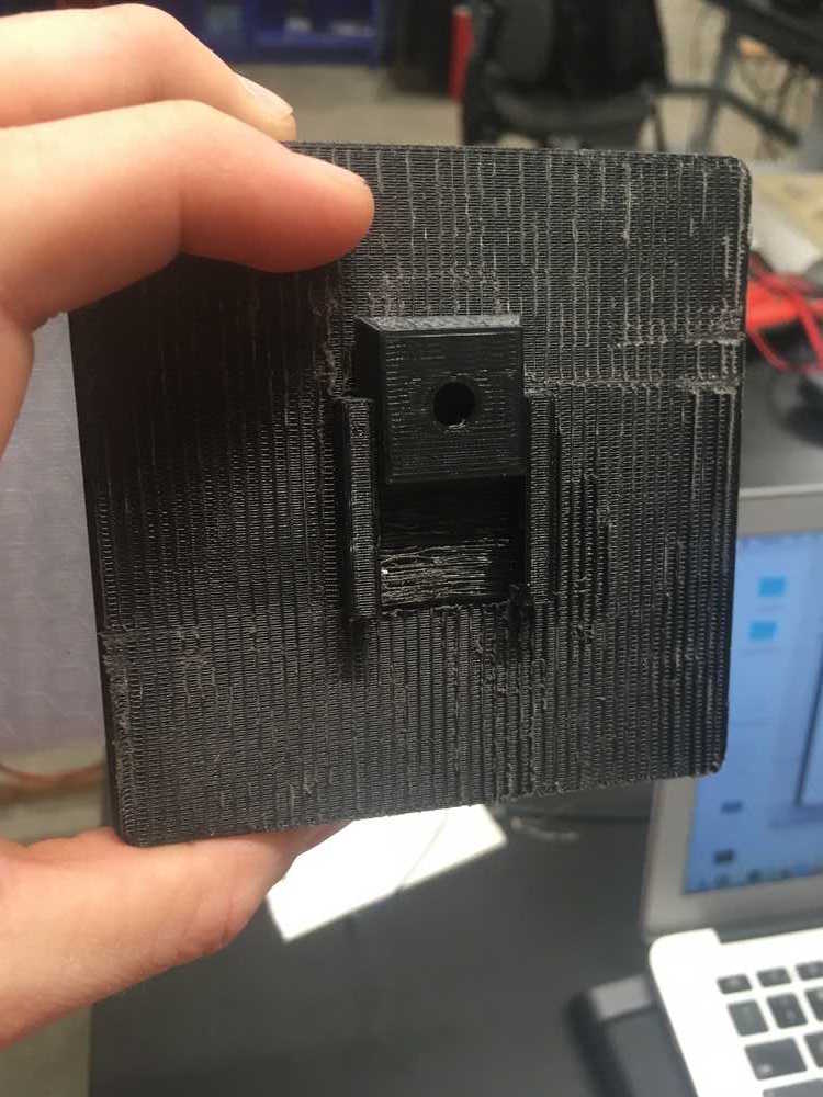
Fig.10 Slide mount for case
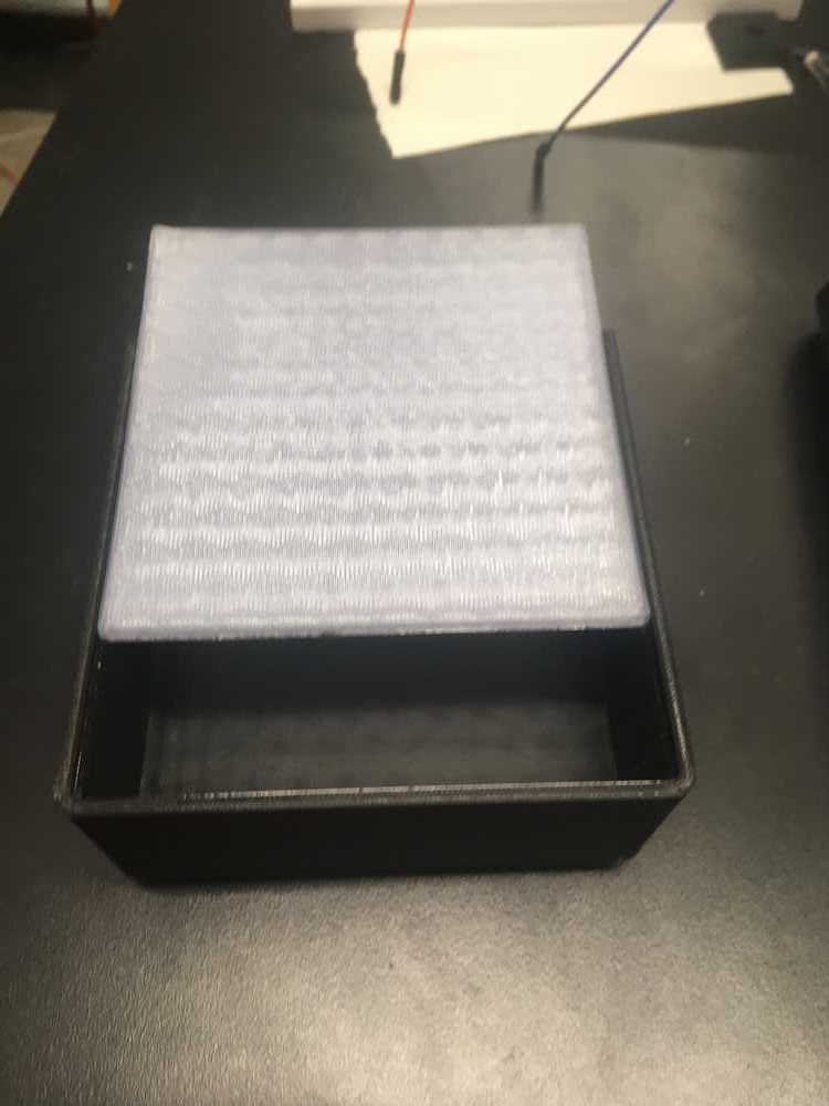
Fig.11 Transparent lid for case
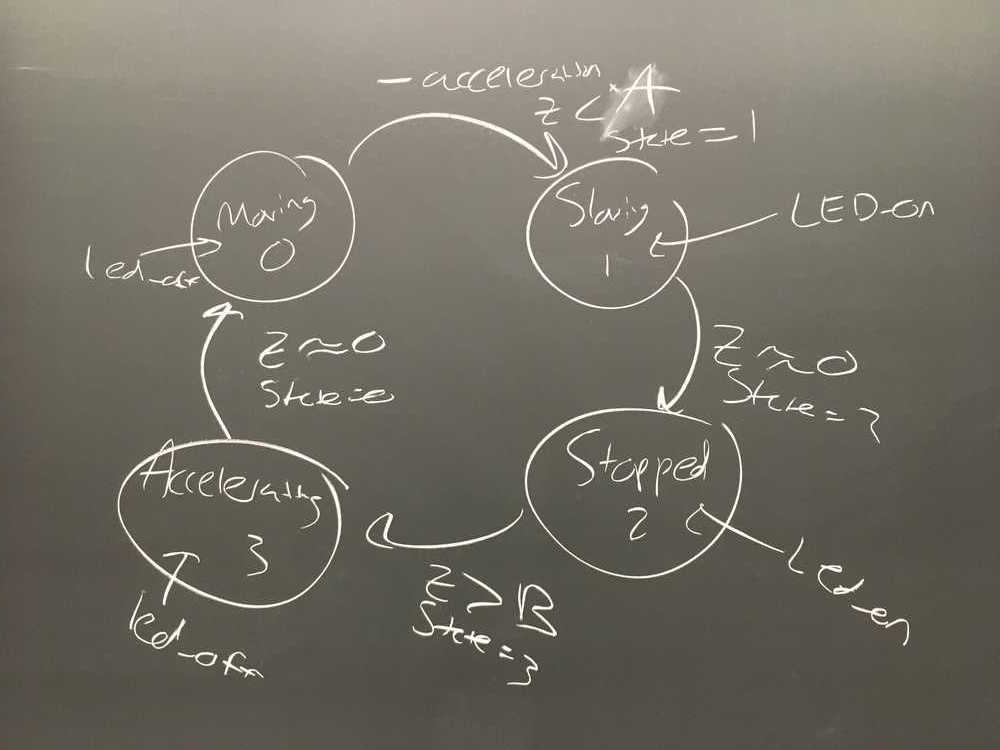
Fig.12 Diagram of code for ADXL and LED relationship, courtesy of our TA Brian Plancher
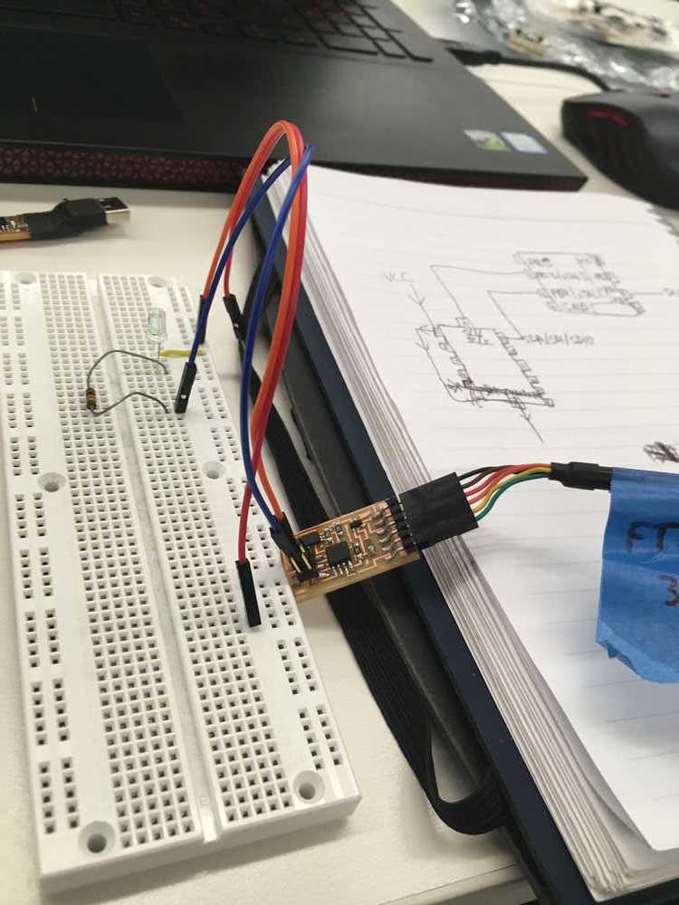
Fig.13 Using a breadbord to protype new code combining ADXL with LED
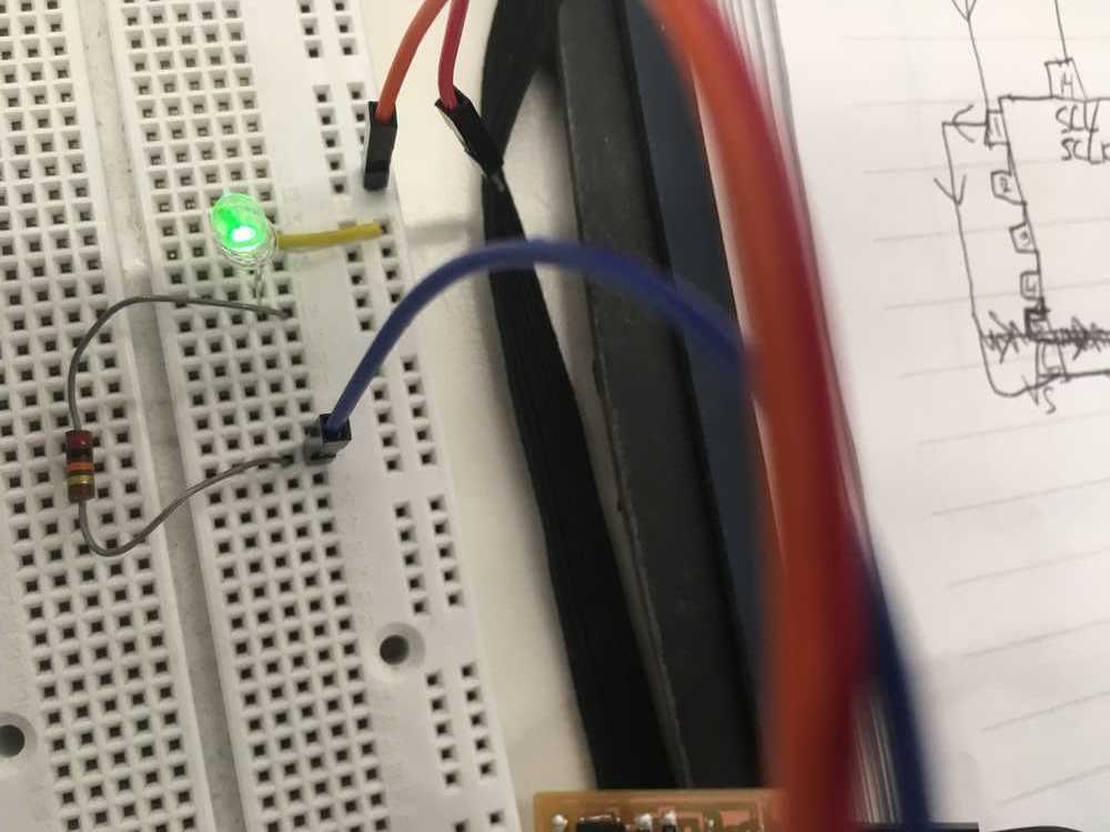
Fig.14 got the lights on...
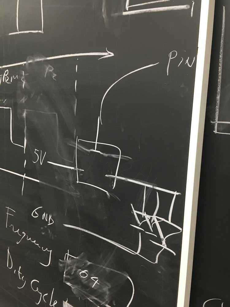
Fig.15 Mosfet Diagram
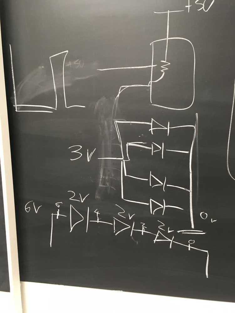
Fig.16 Parallel LED Diagram
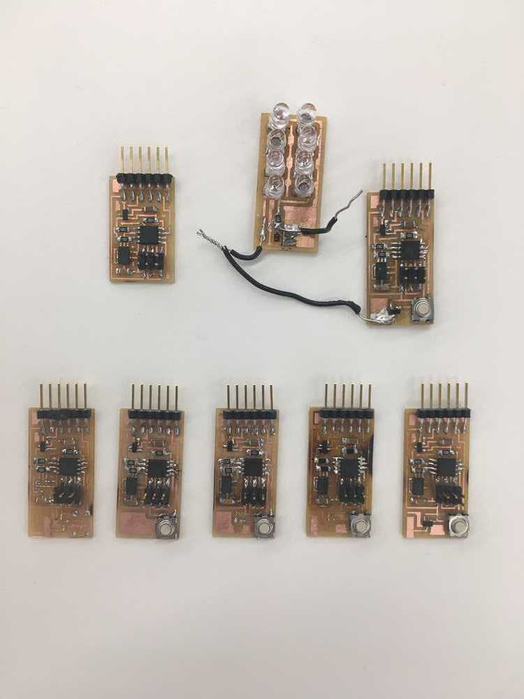
Had some issues when redesigning my boards. It was very difficult to pinpoint the issues. This was incredibly frsutrating. Not pictured are the one or two I threw away and the final.
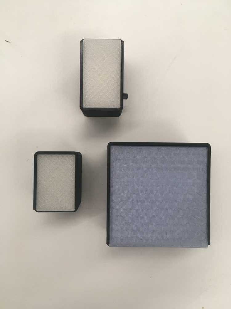
All three iterations of my final housing. One too big, one too small and the final one, on top, just right.
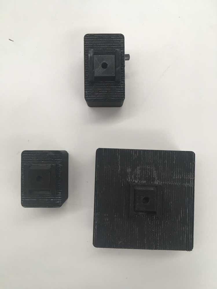
back sides of housing
Final housing front

Final housing back
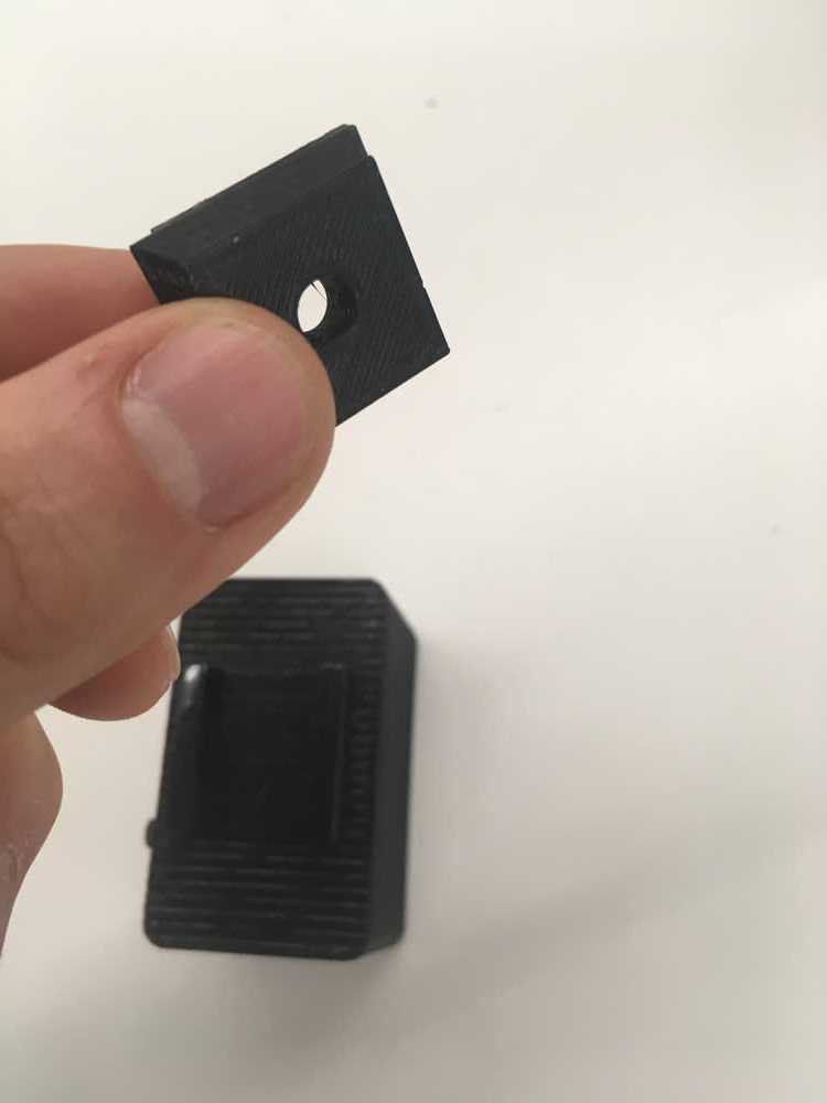
Final housing slide mount
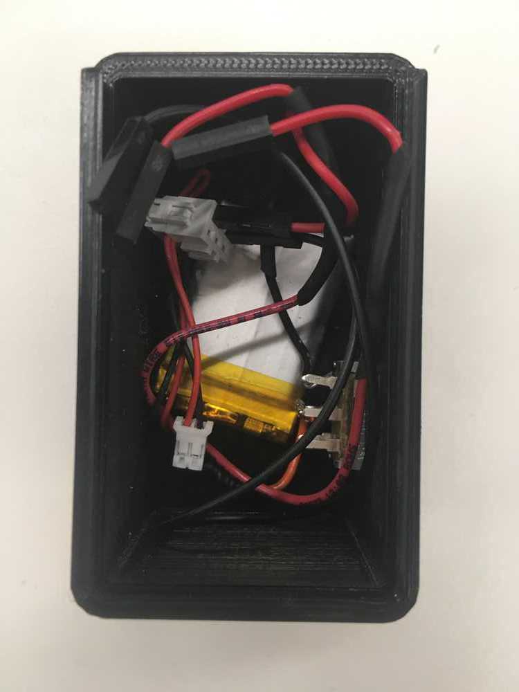
3.7v Lipo battery and heatshrink-wrapped wiring
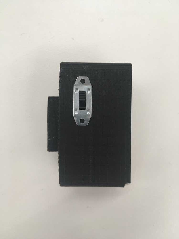
Incorporated a switch into my final housing
Got the switch integrated and working well
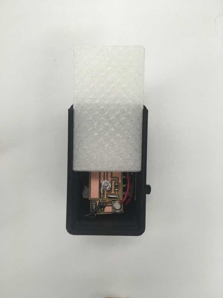
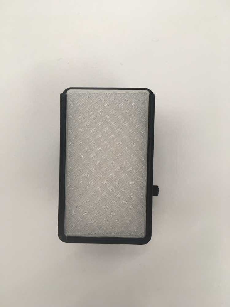
Sliding lid with perfect tolerance
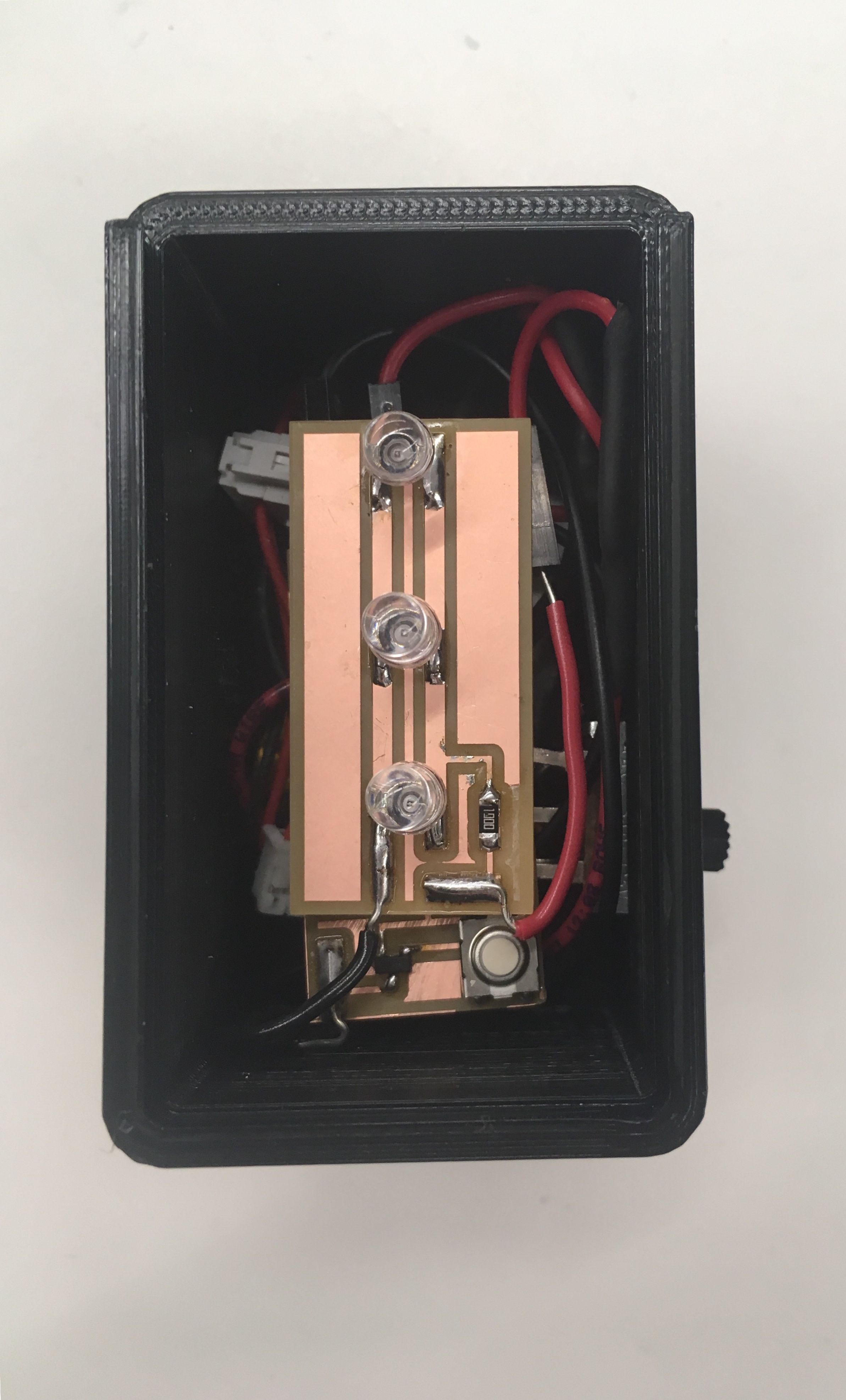
Inside the final piece
The autonomous brake light is complete!