How To Make Almost Anything Neil Gershenfeld

MIT Center For Bits And Atoms
3D PRINTING
Fab labs share an evolving inventory of core capabilities to make (almost) anything, allowing people and projects to be shared. These are my projects.
Electronics Design -
Echo hello-world
10.03.18
I heard that this week was going to be challenging and it lived up to its reputation. I found Eagle not so user-friendly and the first few hours I spent learning the software somewhat frustrating. After all, this is the normal learning curve for most complex software. Eventually I got the hang of it, although I made several mistakes that were not evident until milling, prompting me to update my designs along the way.
The first mistake I made was not checking the design rules concerning the minimum distance between components/traces on the board. This resulted in a couple boards with traces merged together, rendering them useless. I also could have made better use of the grid in Eagle, which you can adjust for varying degrees of granularity. At first, I did not realize that the grid settings were responsible for components snapping into place at times and refusing to do so at others.
After finally tracing a proper board without any shorts, the next series of mistakes occurred as I tried milling the outline that separated the board from the rest of the material. I ended up cutting straight through my first board. I realized that the dpi of the oulitne, which I made in Photoshop, was 72 compared to the 1500 of the board. After updating the DPI something strange happend. Instead of milling the entire outline, the machine only drilled a hole at each corner. Huh? Finally, I relized that the outline was simply too thin and the mod wasn't picking it up. After increasing the outline width from 20px to 60px, it worked just fine.
Luckily, after so much hassle in the design and milling processes, the soldering and programming went off without a hitch.
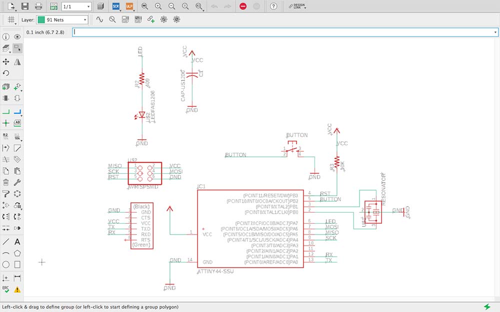
Fig.1 Eagle schematic view
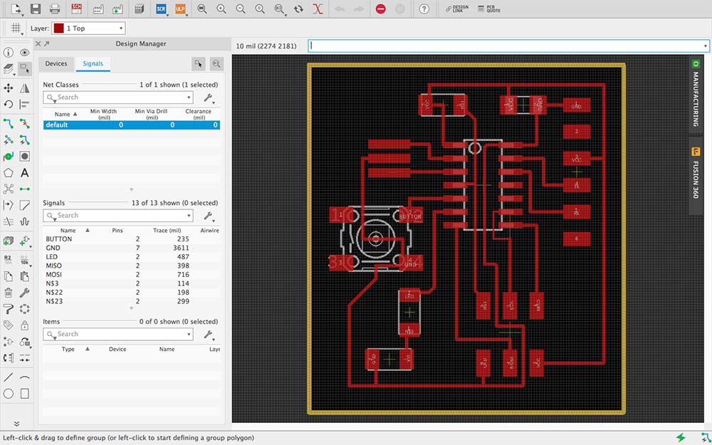
Fig.2 Eagle Board view
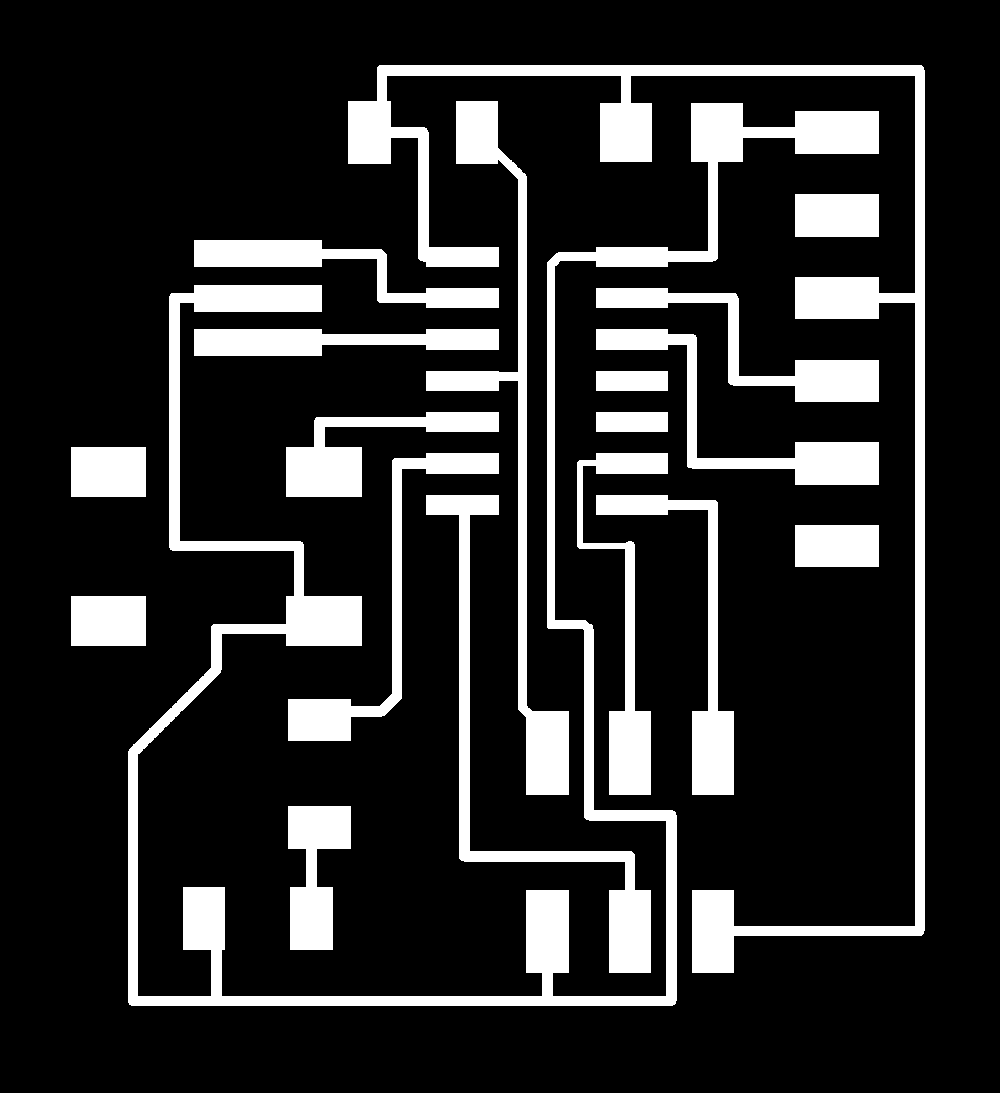
Fig.3 Board exported as PNG
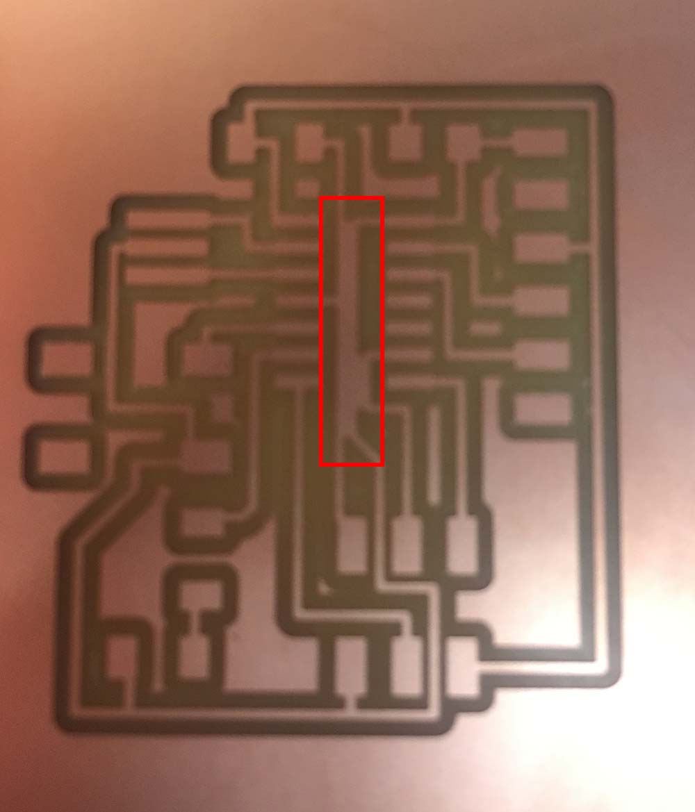
Fig.4 Traces merging, aka "shorting"
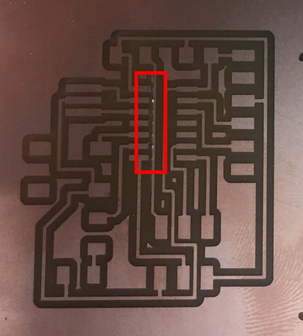
Fig.5 Another failed attemp, tried to fix with razor

Fig.6 First attempt at outline in Photoshop
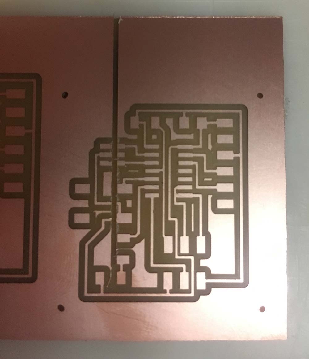
Fig.7 Outline above destroys board due to wrong DPI

Fig.8 Fix outline by increasing the border stroke
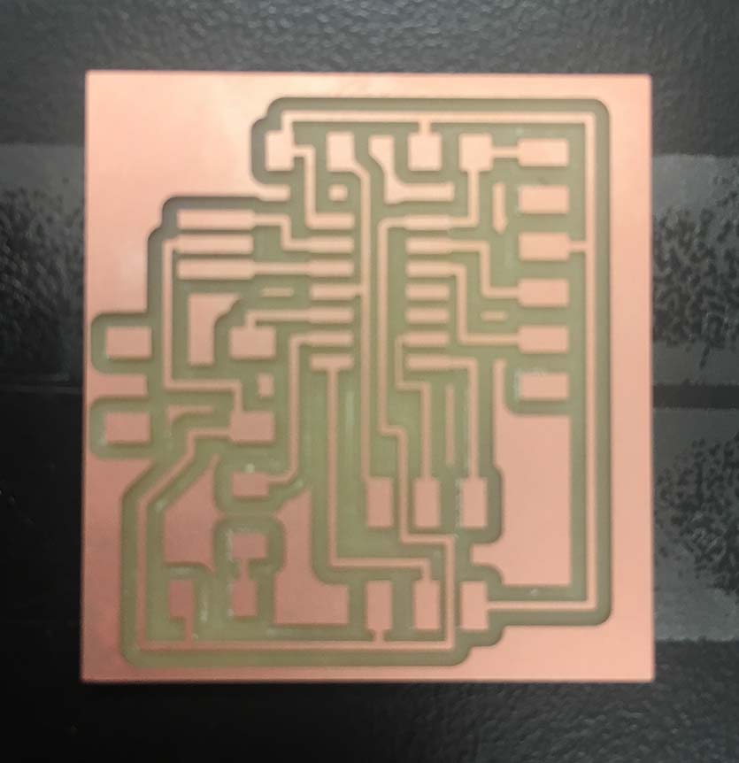
Fig.9 Finally, a decent board
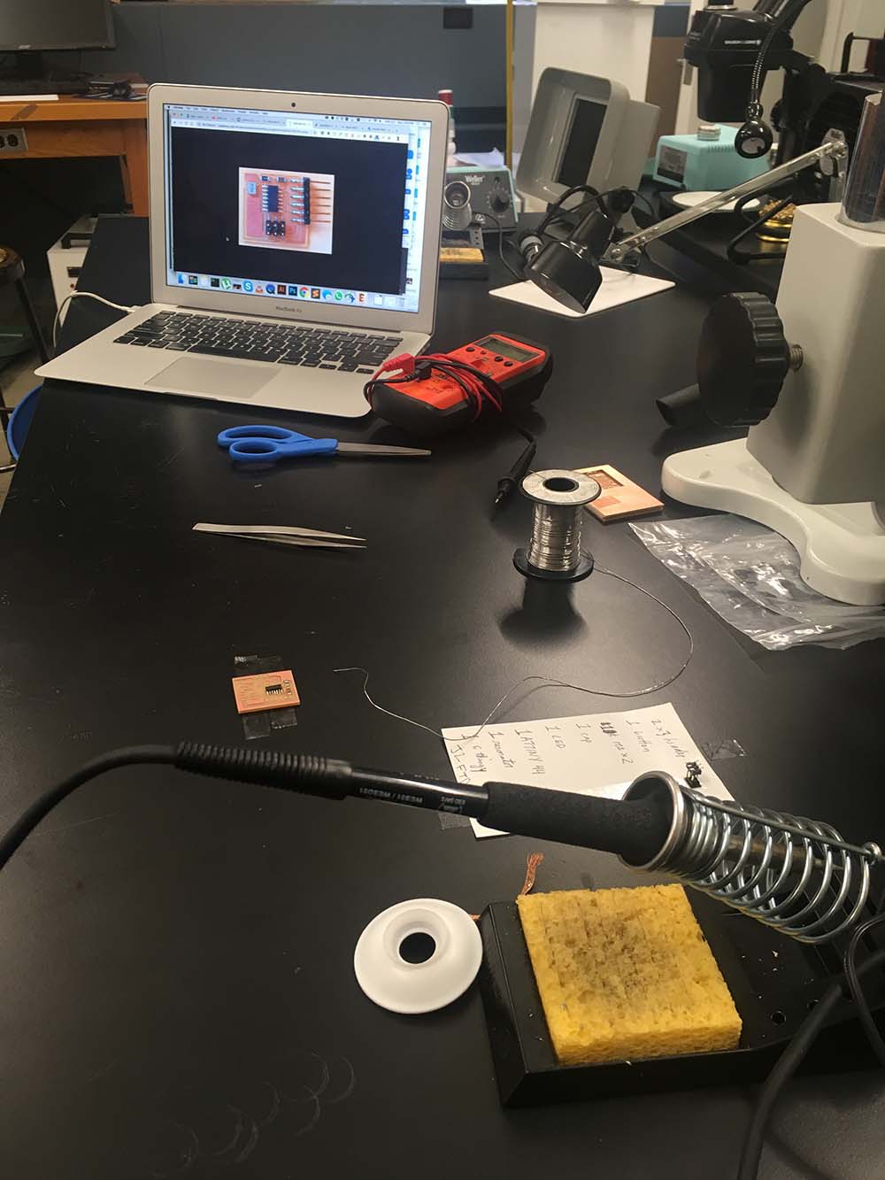
Fig.10 Soldering set up
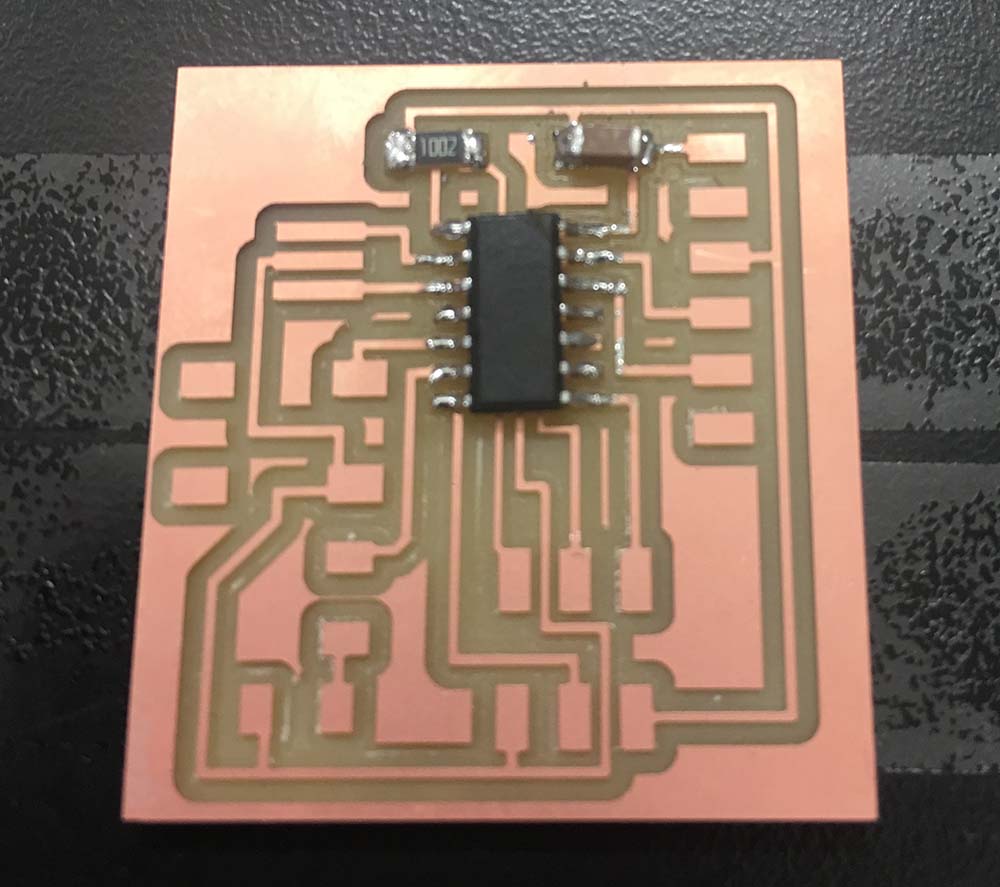
Fig.11 aTTiny44 attched in correct orientation
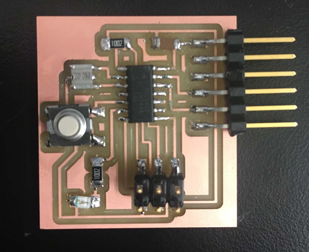
Fig.12 Board complete
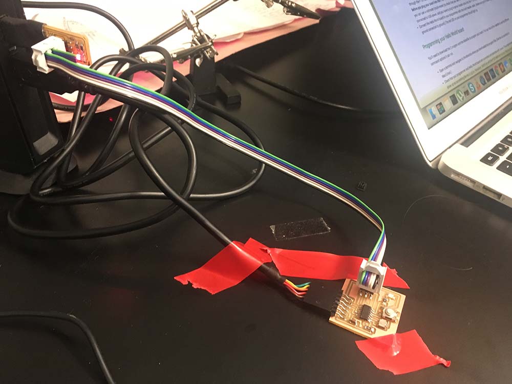
Fig.13 Board plugged into programmer and computer correctly
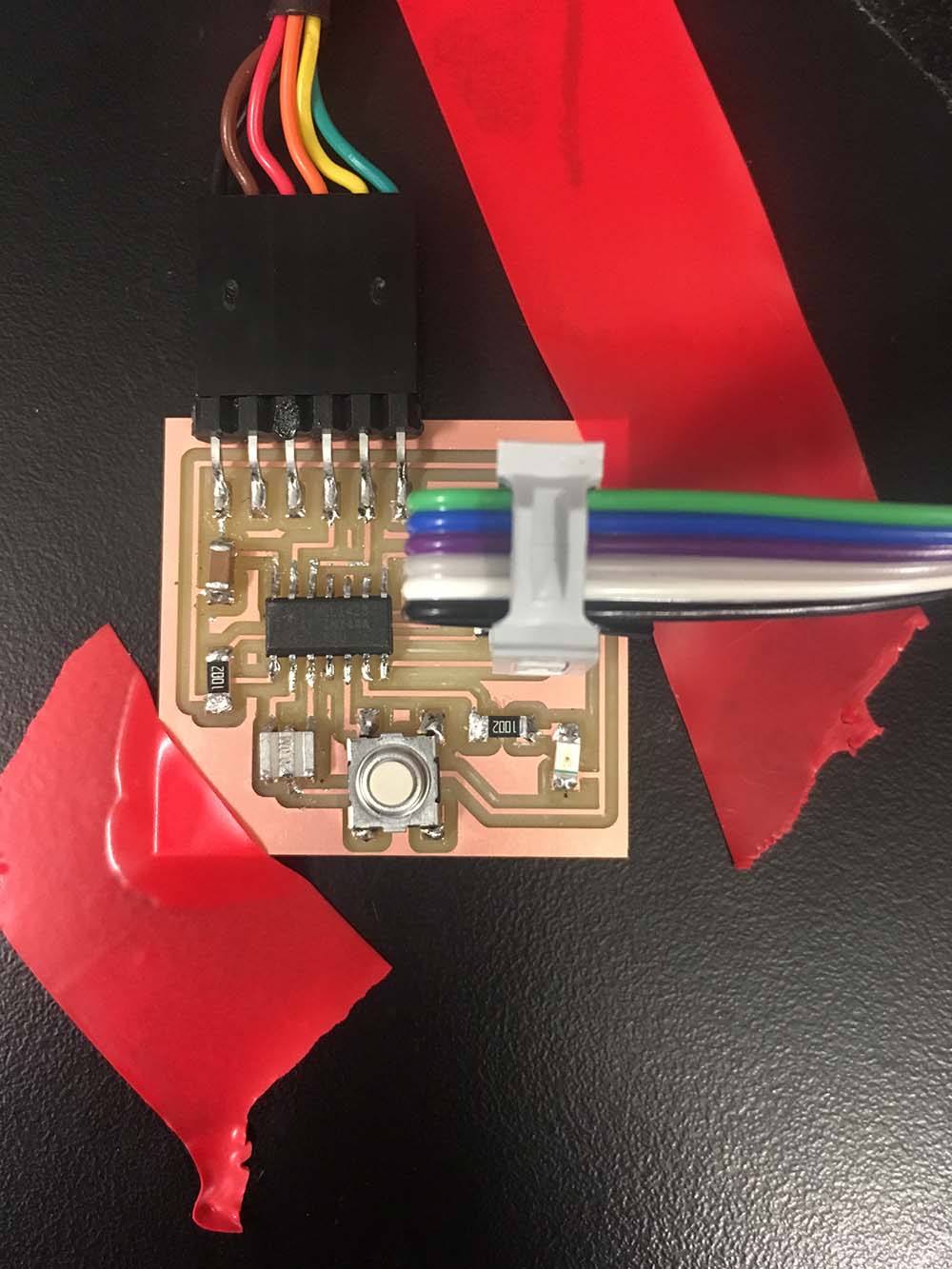
Fig.14 Tape to keep board flat
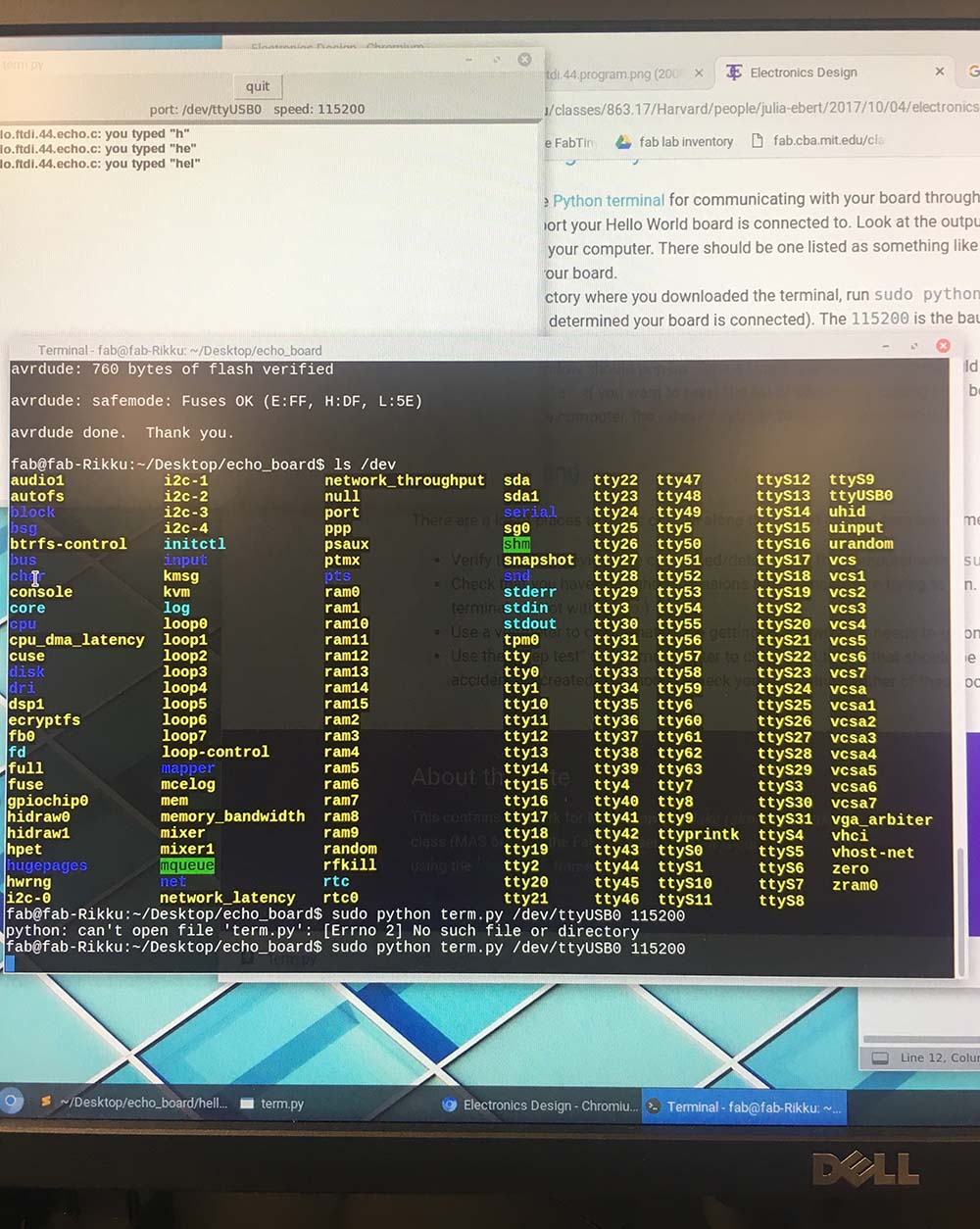
Fig.15 ls /dev command showing board at ttyUSB0
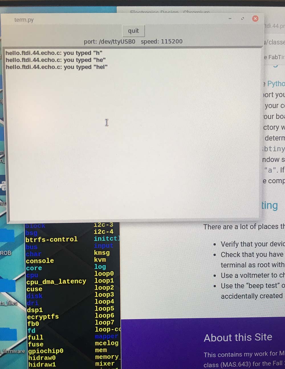
Fig.16 Echo porgram working successfully
Fig.17 Video of Echo program in action