How To Make Almost Anything Neil Gershenfeld

MIT Center For Bits And Atoms
OUTPUT DEVICES
Fab labs share an evolving inventory of core capabilities to make (almost) anything, allowing people and projects to be shared. These are my projects.
Output Devices -
Speaker with Potentiometer
11.7.18
This week our individual assignment was: "add an output device to a microcontroller board you've designed, and program it to do something".
The previous week's assignment was to design our own input device and use it to measure something; I sort of cheated in that I copied one of Niel's boards, namely the accelerometer. So my goal this week was to make another input device to atone for last week, coupling said input device with an output deivce that would saitsfy the requirements of the present week. Rob and my TAs suggested a simple potentiometer for an input device, one that I could couple with a speaker for output.
One of my TAs suggested that I try to reverse engineer Niel's "light" board, since it seemed like one of the simpler boards. The potentiometer was working well when we measured the voltage, but there was still no sound coming from the speaker. When we took a closer look at the speaker board, we realized that we forgot the mosfet. That's what I get for trying to combine two boards! With the clock ticking, instead of designing a new board, I managed to freewire the mosfet and voila! It worked!
The traces you see on the right are for the final iteration of the board, including the mosfet. I never had a chance to build this better version without the freewired mosfet. I tried once but there was something wrong with my DPI and the traces were too spaced out for the ATtiny pins.
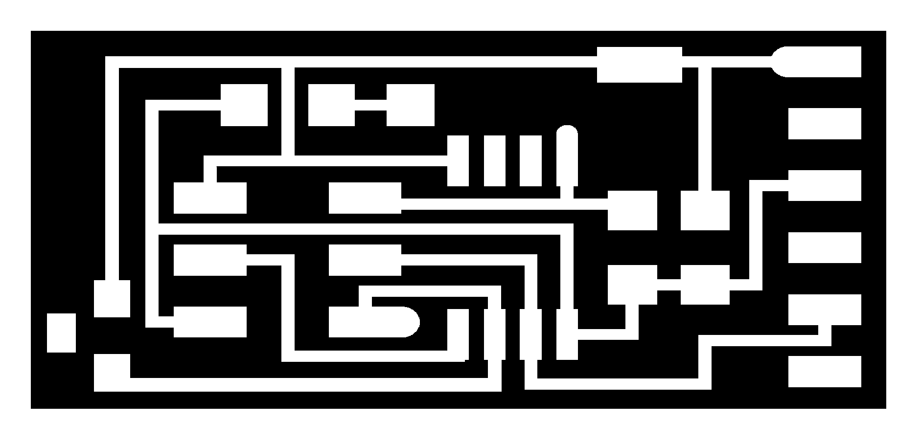
Fig.1 My board, a combination of "Light" from Input Week and "Speaker" from Output Week

Fig.2 Interior of Board
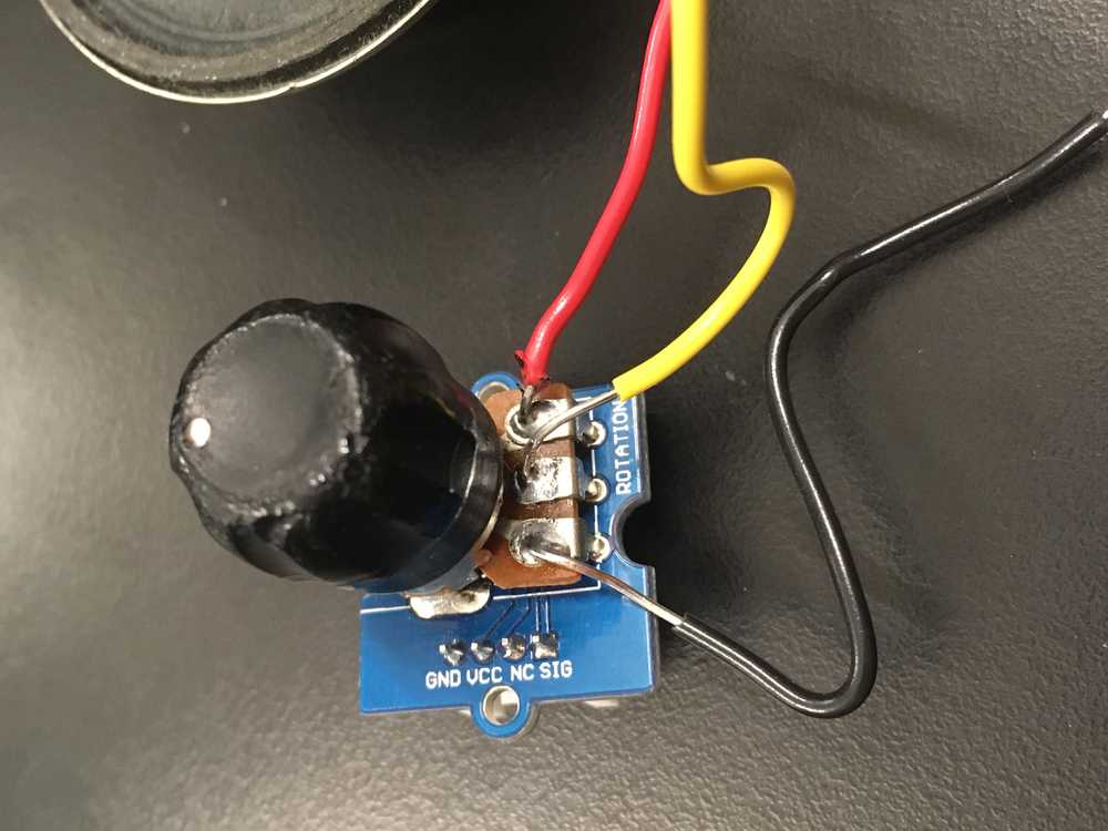
Fig.3 Potentiometer
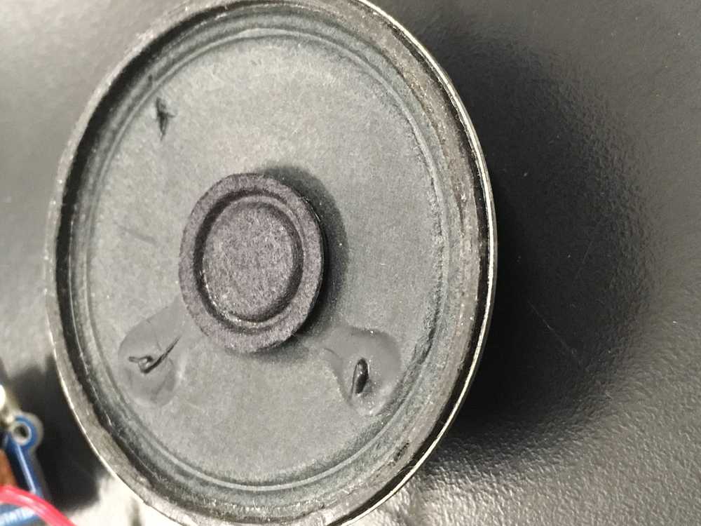
Fig.4 Speaker
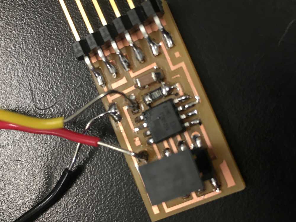
Fig.5 Board pre free-wired MOSFET
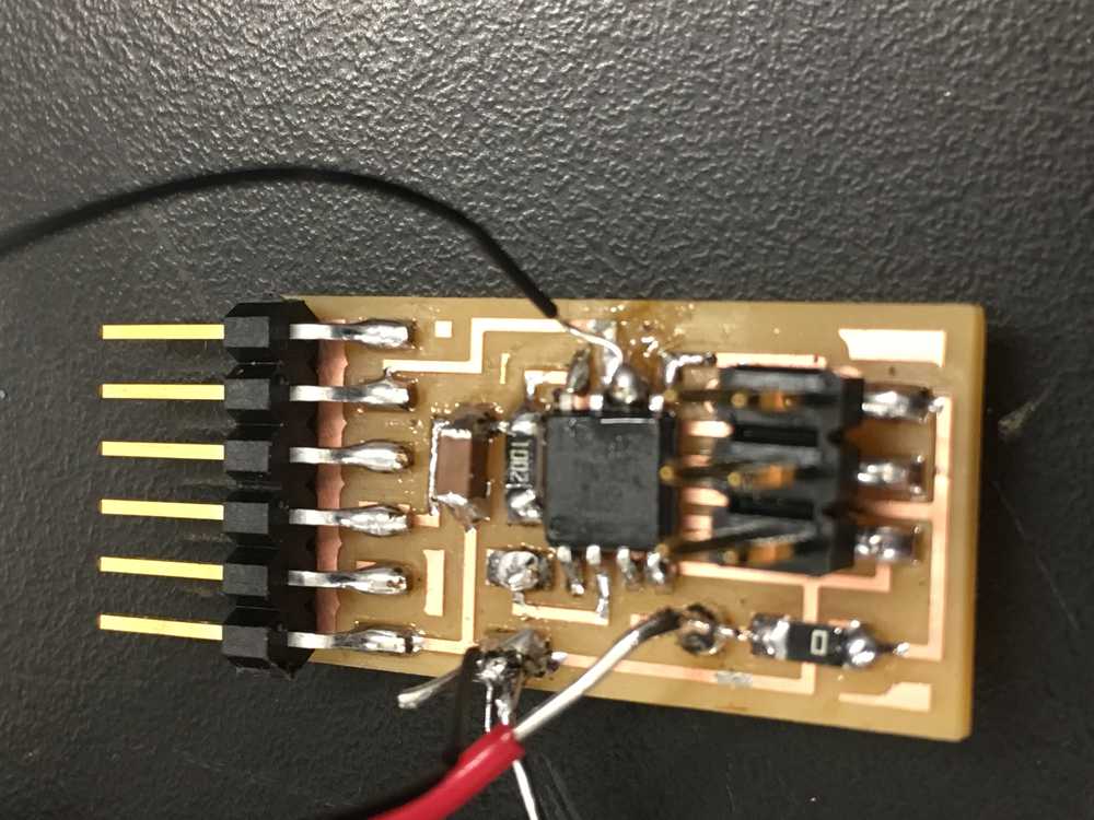
Fig.6 Board post free-wired MOSFET
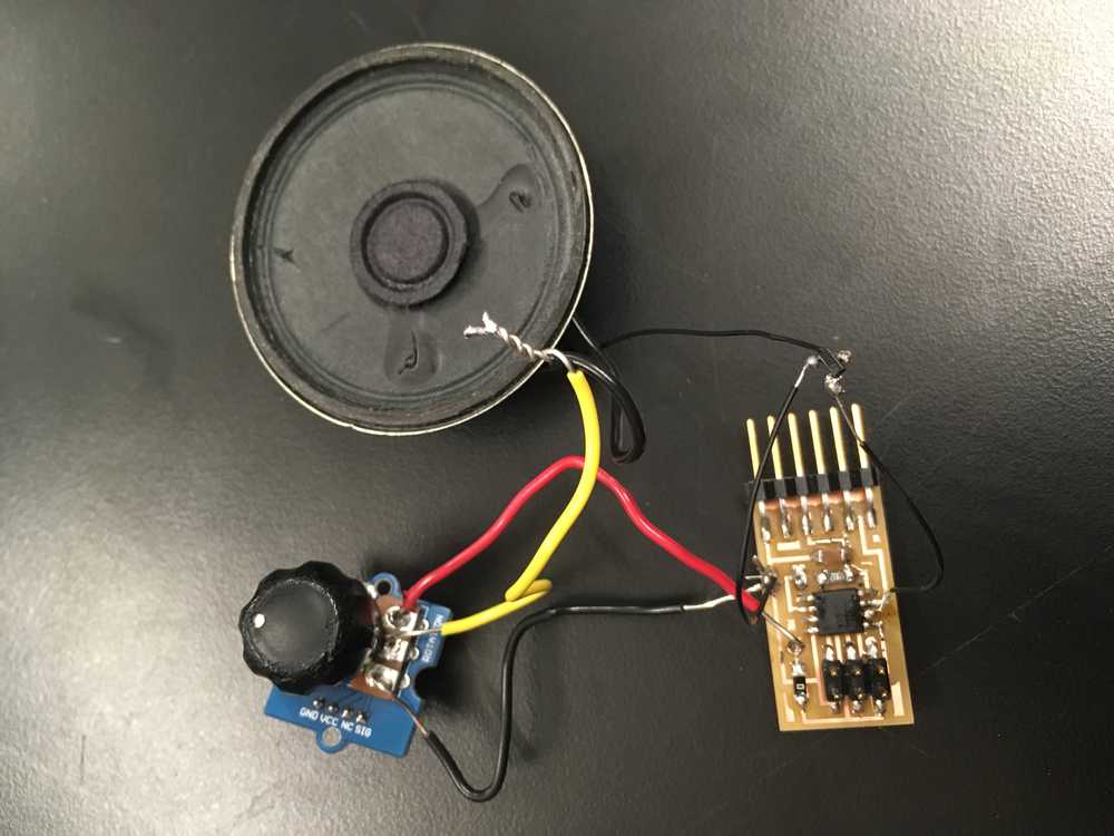
Fig.7 Speaker, potentiometer and free-wired MOSFET all attached to board
Fig.8 It's working! Notice how the volume goes up and down as I turn the dial.
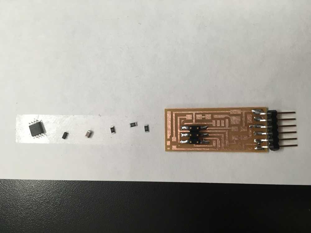
Fig.9 Beginning to stuff rediesgned board that wont need free wiring. DPI was slightly too small, so pads are too far apart. Need to re-mill it. Can also get rid of 0ohm resistor.