This is the tracking page for my final project! As mentioned in week 0, I decided upon pursuing the project of a remote control for an electric longboard-like device. I hope to combine most (if not all) of the skills I learned in this class to this project.
For ease of tracking, I’ll switch between updating the electronics and physical components so that it is easier to follow rather than jumping back and forth between things I did.
For my networking week, I chose to look into using nRF24L01+ modules for my wireless connection. I’ve heard both good and bad things about all of the wireless communications modules provided in the fab lab and was hesitant to use them. However, I found a lot of YouTube tutorials on using the nRF24l01 modules with Arduino, so I ended up successfully doing that for networking week after not too much struggle.
So, I set out to make a board that could accommodate the radio module with an ATtiny44. I set all the pins of the module on analog pins (except for GND and VCC of course). I had a nicely routed solution—the module situated on one side of the microcontroller and a LED and analog pin on the other side. I had decided by this point to abandon the idea of a novel touch sensor like I tried to build in input device week and decided to stick with the good ol’ run-of-the-mill potentiometer. Luckily it was no different to the board than the soft potentiometer I was thinking of using after my input device week.
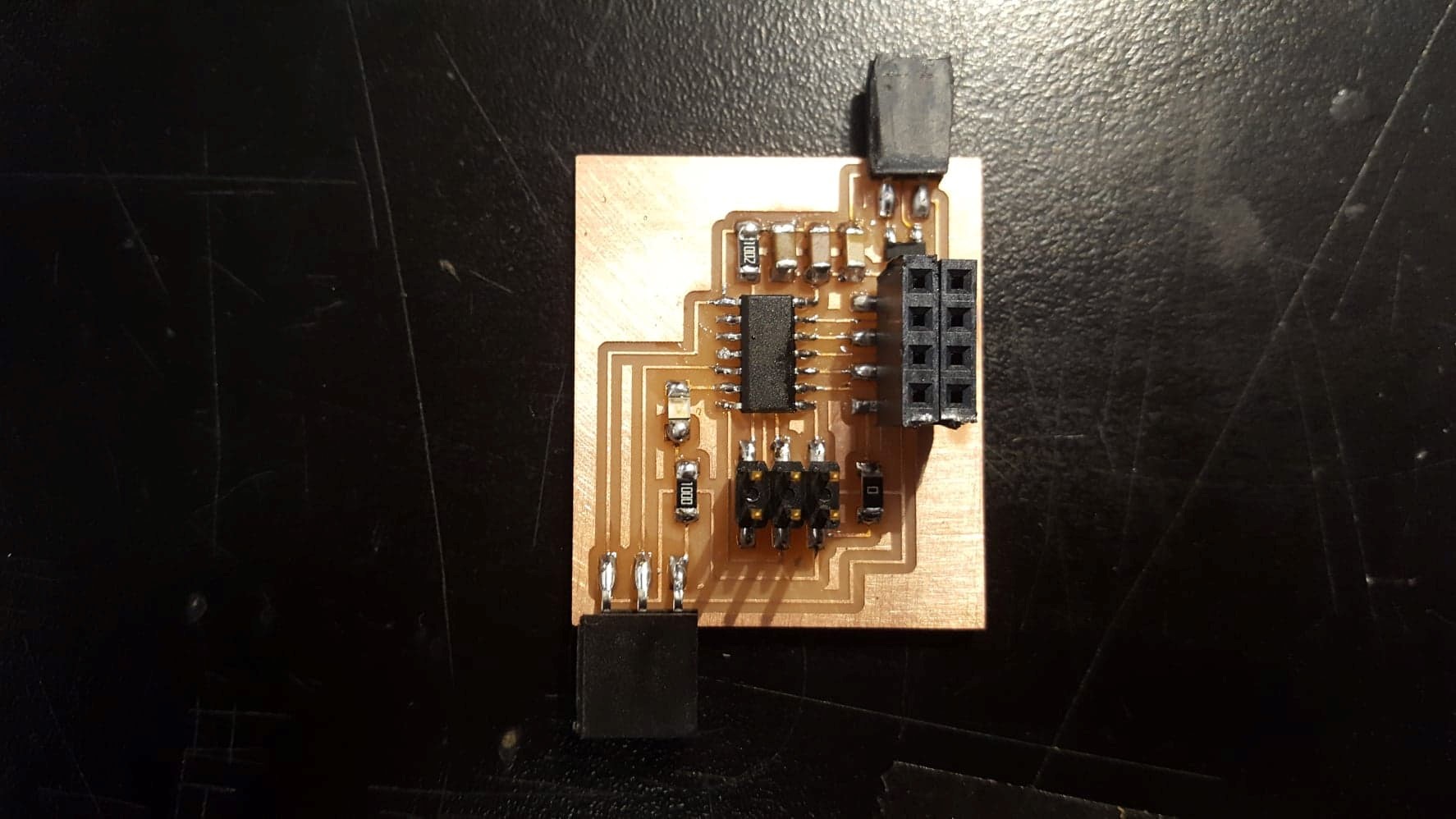
At first, I just wanted to make sure I had power, so I wrote a small Arduino code to set the LED pin to high, and luckily, it worked. Next, I wanted to make sure the board was getting a good reading from the potentiometer. I didn’t have a serial port set up, so I utilized the example code in Arduino called “Analog Input” to see what signal I was getting. Basically, the reading of the pot was set as a time delay for the light to blink, so I could visually see what values I was getting. However, this test did not work. I knew the code worked, as I had used it in a previous week, so it had to be a problem with the board. I scratched my head over it for a while, and I soon realized I had put the output from the pot on a PWM only pin. So, I went back to eagle and moved the pins to a better position so that I could actually get a reading. I also added the larger 1 Amp voltage regulator (just in case the future wireless signal required more current).
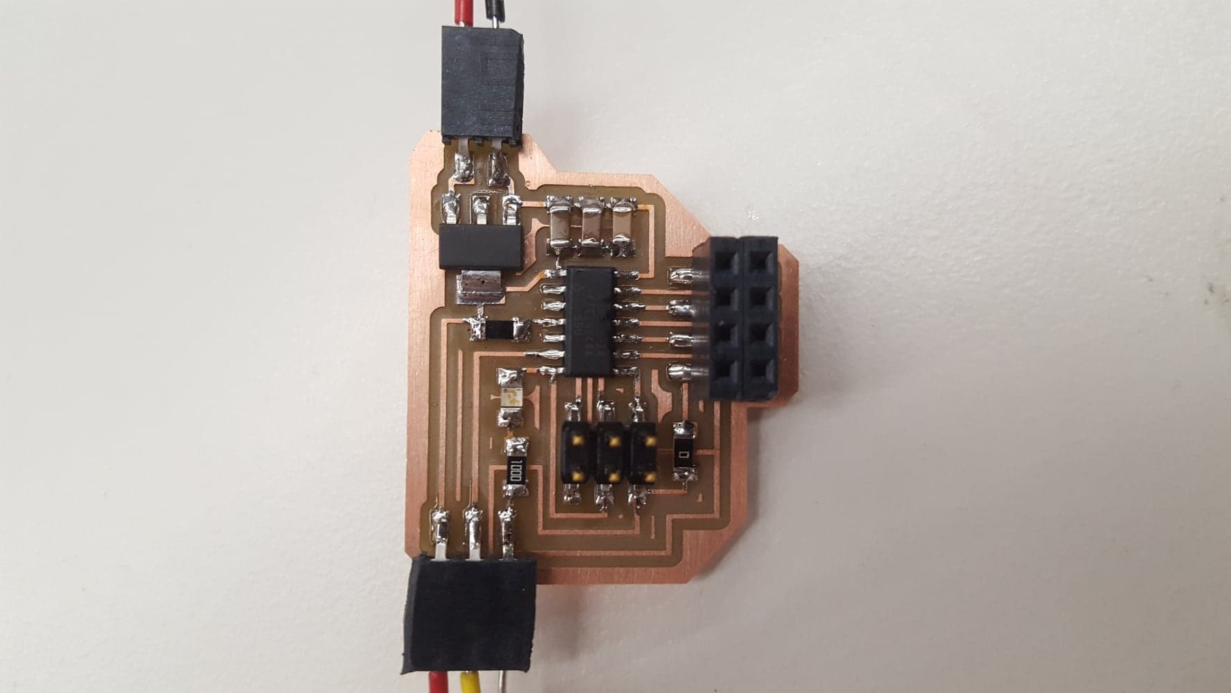
On this board, I went through the same tests and got the light and analog input to work! Now it was just a matter of making it wireless.
I searched and searched for anyone on the internet who had implemented the nRF24l01 radio modules with an ATtiny44. I literally only found one example from a person who had previously made a garage door opener******** for the fab academy. I downloaded all the libraries he mentioned, and I took a stab at it. Either I wasn’t as knowledgeable of these modules as I would have liked to have been or his documentation was a little lacking. I tried several ways, trying to only send a simple package, but I kept getting ambiguous errors in the Arduino IDE.
By this point, I’ve been pulling at strings working on getting the radio modules to work for days with no significant success, and I decided to move on with the more physical components of my final project.
After the physical components started coming together, I came back to the electronics with a more compact timeline. Considering I wasn’t getting anywhere with the wireless aspect, I decided to try to make a wired connection.
Instead of making a new board for making a functional wired network between the remote and another board, I used my first board that ultimately failed. I again used the “AnalogInput” example in Arduino, this time making two versions: The transmitter version set pin 0 (as a digital output) to high when the light was on, and the receiver set the LED pin high when its pin 0 (as digital input). With this, I got some simple digital communication, and the two boards began to blink at the same speed (which was determined by the potentiometer on the transmitter board).
I wanted to build a board with an ATMega328p, as its pins are basically the same as the Arduino board and would therefore be plug-and-play for me to use the radio modules in the way I used them in week 8. However, I ran out of time and settled with this wired digital communication.
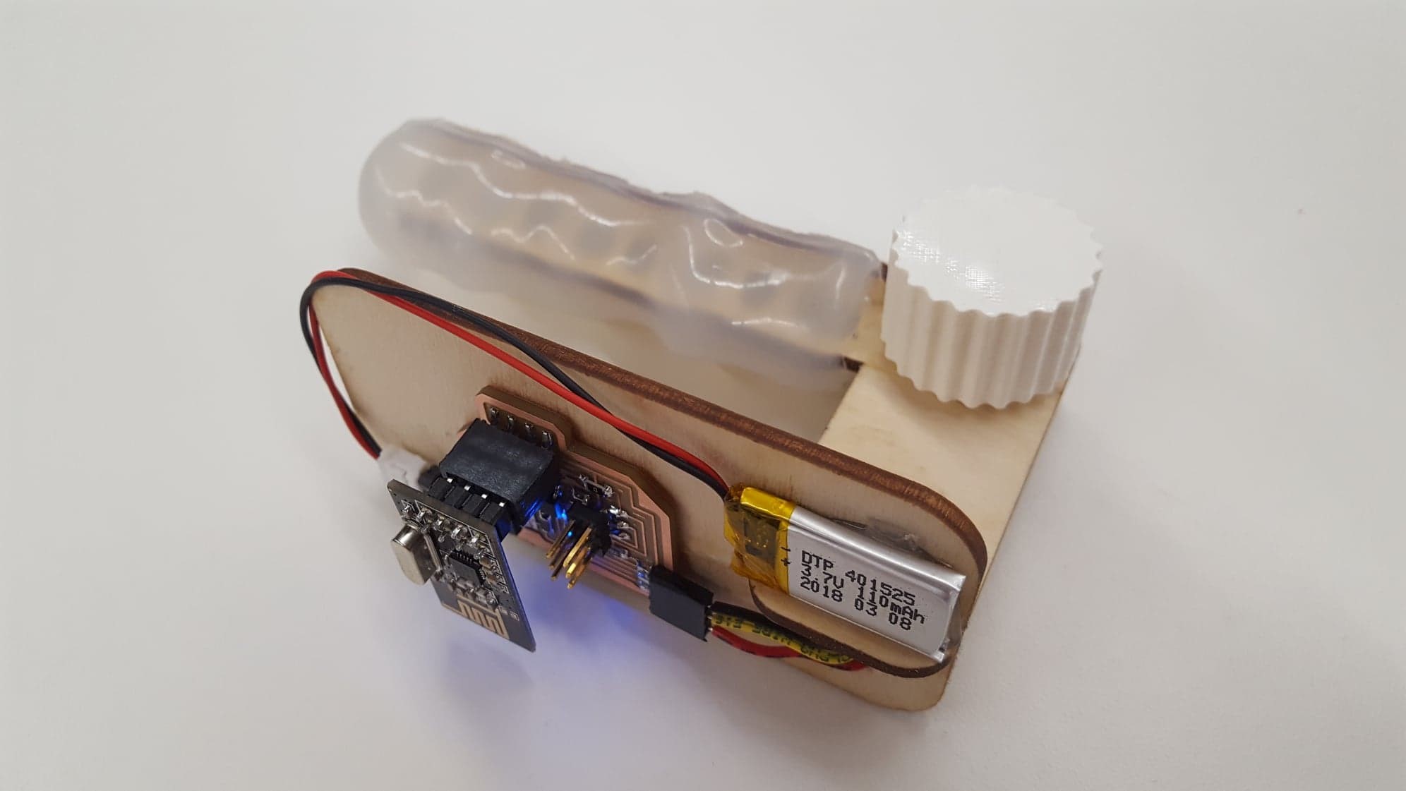
For the design of the handle, I chose to use laser cut wood with a nice gel grip.
I wanted to get an ergonomic grip like my device made in input device week. However, this time I wanted to use my vacuum form mold (from wildcard week) to make the part that fits to the hand. So, I made a laser-cut wood skeleton in SolidWorks based on some quick measurements from my hand and cut it out on the laser cutter, soon to have a gel grip added.
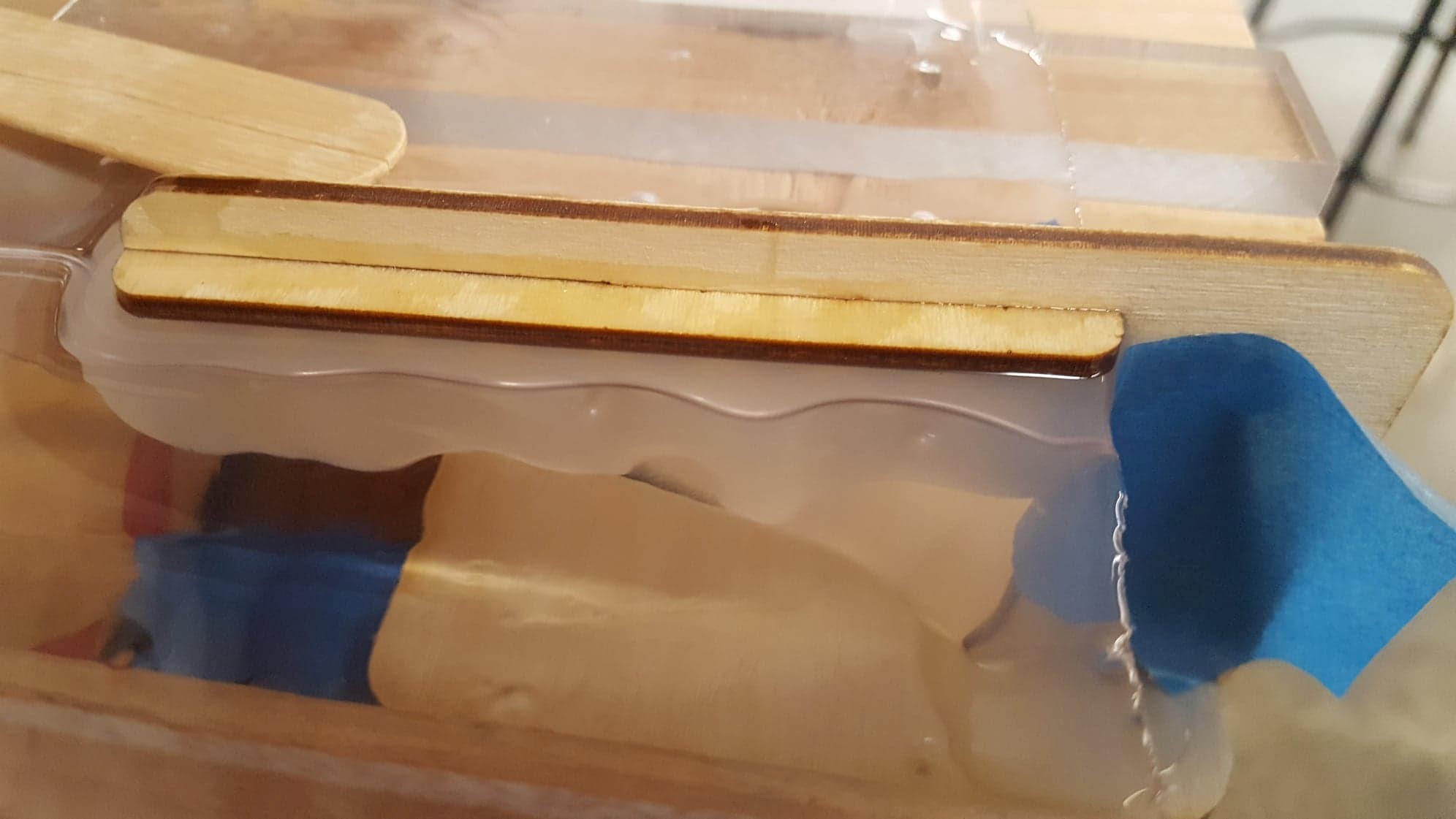
For the gel grip, I used my product from wildcard week in this class. I used that vacuum form shape to make an inline mold for my skeleton. I simply cut a notch out of the form and slotted the skeleton into it. It was very difficult to get everything settled to pour in the EcoFlex, but I eventually got it figured out!
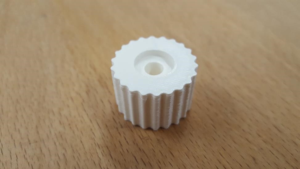
As for the 3D printed knob, I made a relatively straightforward design in SolidWorks. The actual problem was finding a working printer--two that I tried didn't work and only partially printed what I wanted. I got aggravated with the third failure on the printer and fixed the printer (there was a lot of gunk stuck in the extruder head from previous users and the flow was blocked). Eventually I got the piece I wanted.
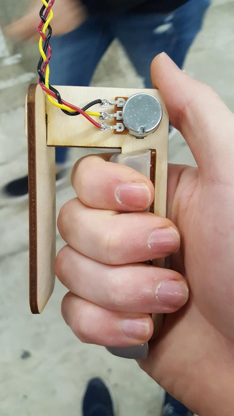
At this point, most everything is coming together. After giving up on the wireless aspect, I decided to go ahead and pull everything together. I used a bit of glue to hold the press-fits of the skeletons together better and I used hot glue to hold the electronics down. I decided for the demo that I would merely have the LED blinking at a speed determined by the pot and to have the radio module mounted instead of having a wire transmit a signal to another board. This way it is easier to imagine is as the fully functional remote controller. In the future, I hope to maybe figure out how to either run the nRF24l01 modules on the Attiny44 or another board.