Assignment 1
Computer-Controlled Cutting
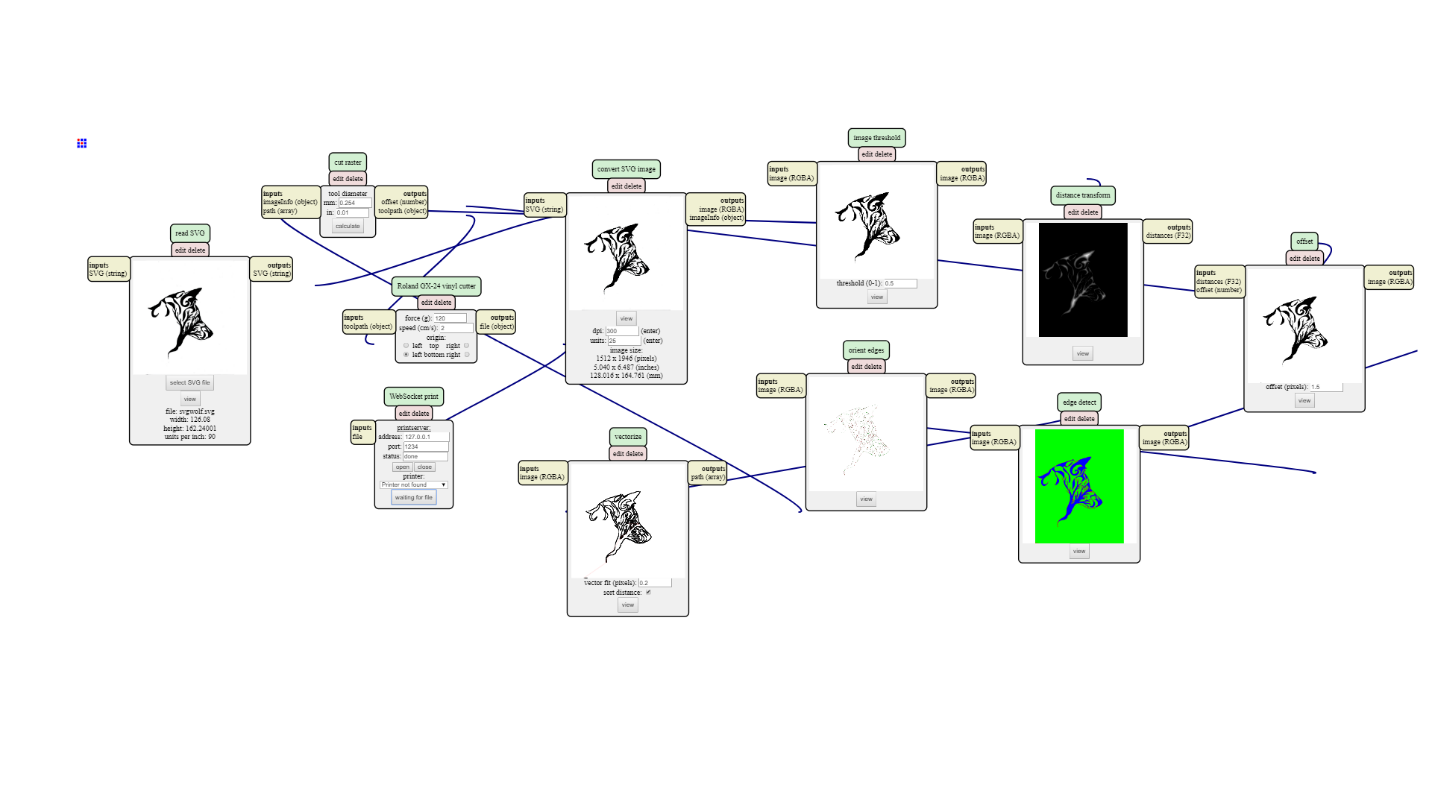
For the first part of this week's project, I cut a sticker out on a vinyl cutter. After familiarizing myself with how to adjust the knife, the rollers, and the materials, I found a nice abstract piece of art online (credit to Bismark Alphawolf, whoever you are).

Then I utilized Inkscape to turn it into a sharper .png file, which I then uploaded to the server-based program that turns .png files into a toolpath for the printer. However, this did not work super well, as it wasn't well recognized by the program. So I went back into inkscape, vectorized the image, and saved it as an svg, which I then ran in the tool path converter program again (this time with more success).
First few tries didn't work out so well. The first ones were too small for the amount of detail that this image had. A few tries later, I realized I wasn't cutting deep enough, but I eventually figured it out!
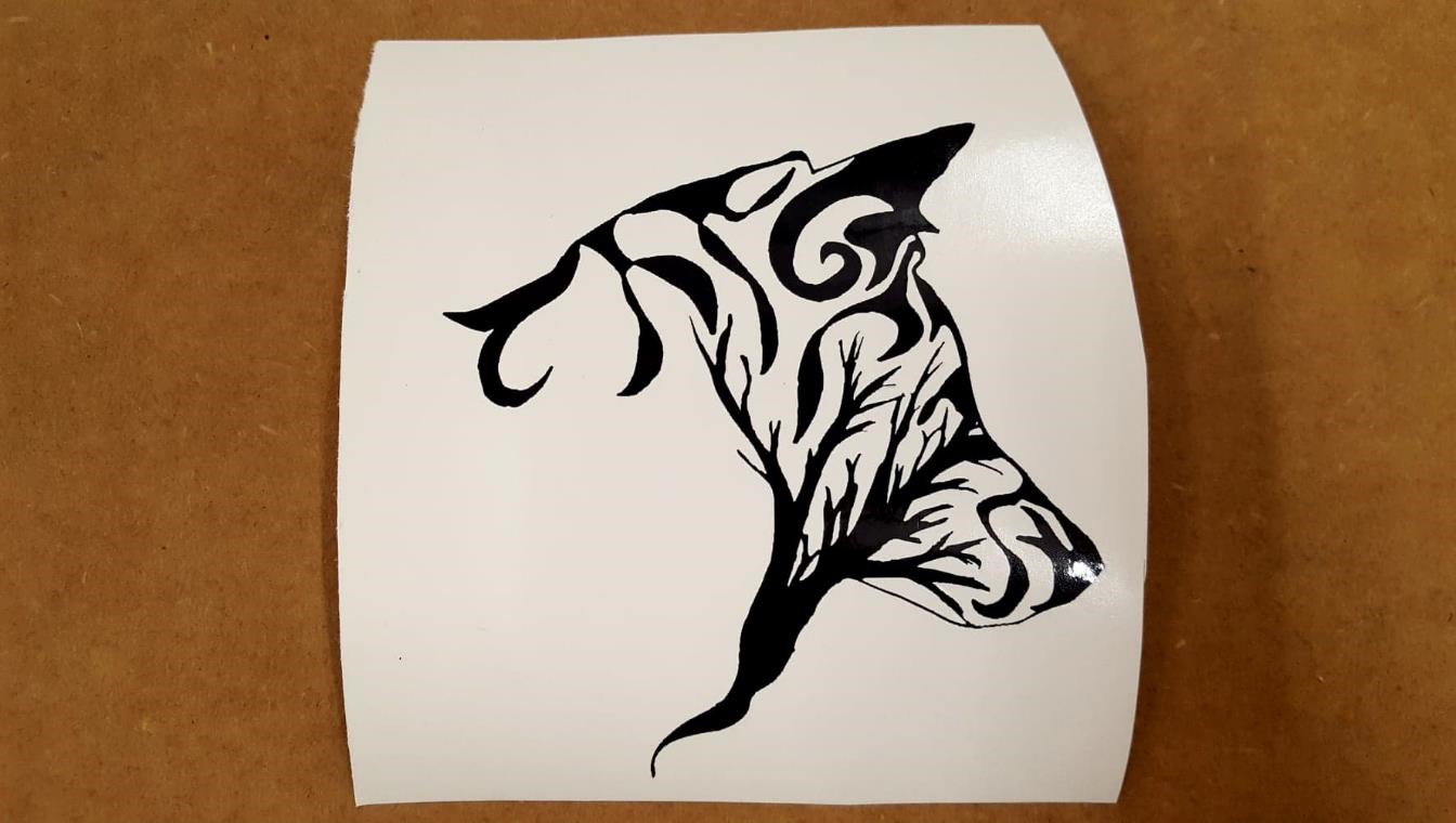
I'm not sure where I am putting this overly intricate sticker yet, but I will likely need to use transfer paper when I do!
For the next part of this week's assignement, I created a relatively simple, parametric contruction kit out of 1/4th inch plywood.Just to serve as a refresher on the basics of the laserprinters:
- Turn on the ventilation system and the printers
- Set X-Y coordinates to the desired home
- Load the .dxf or .dwg into the CorelDraw and adjust printer settings for material
I created a test piece within CorelDRAW to test the fit with different sizes of slots in order to know how to account for the kerf:
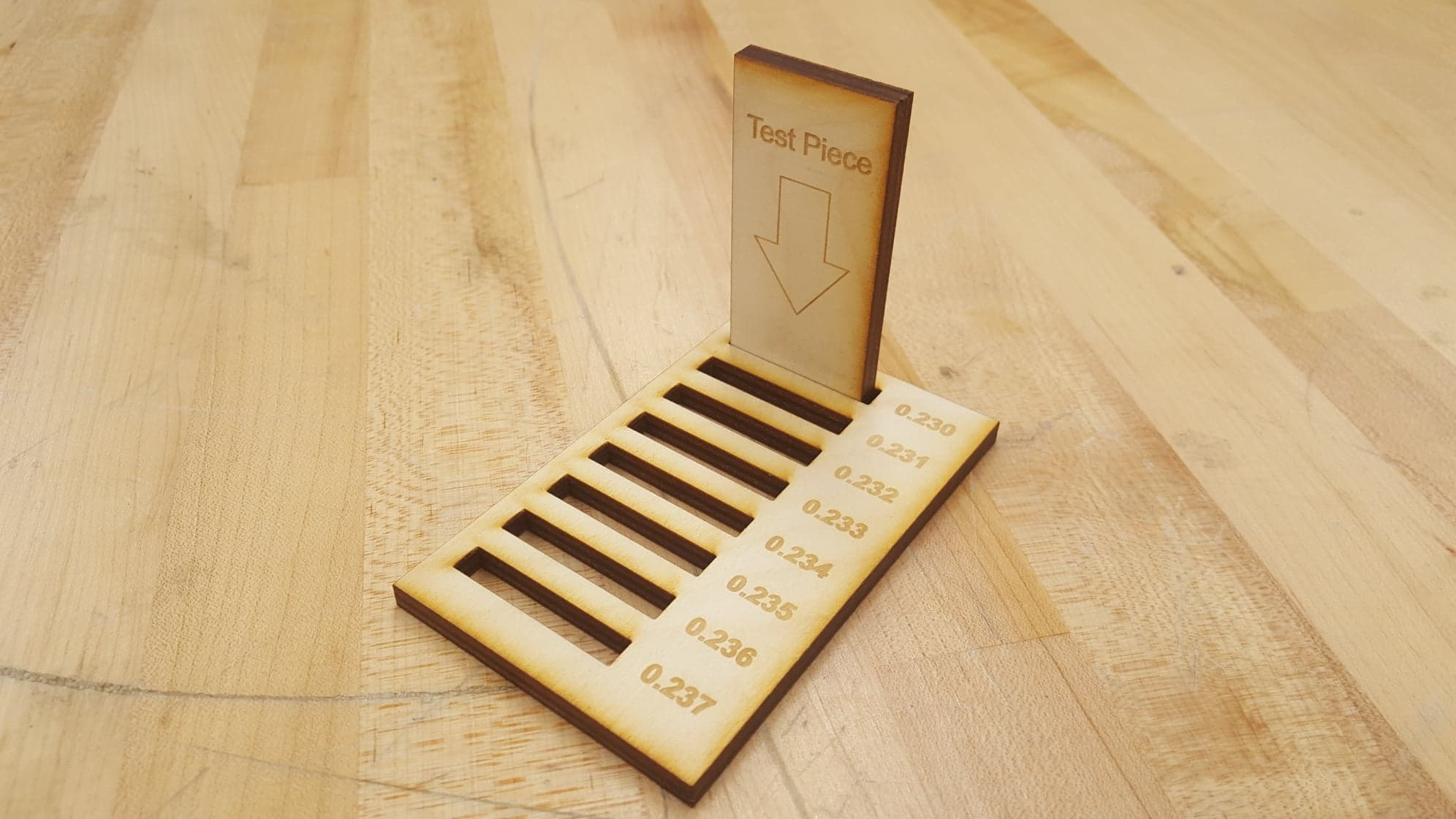
The fit was fairly nice press fit in the smallest slot I made, so I decided to utilize that size of slot in the next part of my design.
My original plan for this project was to make a construction kit out of basic slotted pieces and special pieces that could hold shafts and gears. The plan was to make square shafts that were the thckness of the material, which would have gears pressfit onto them and would rotate in a looser hole that would be attached to the basic construction frame. However, a class was being trained on the lasercutters I was using, so my time was limited and I stuck to the more basic construction blocks.
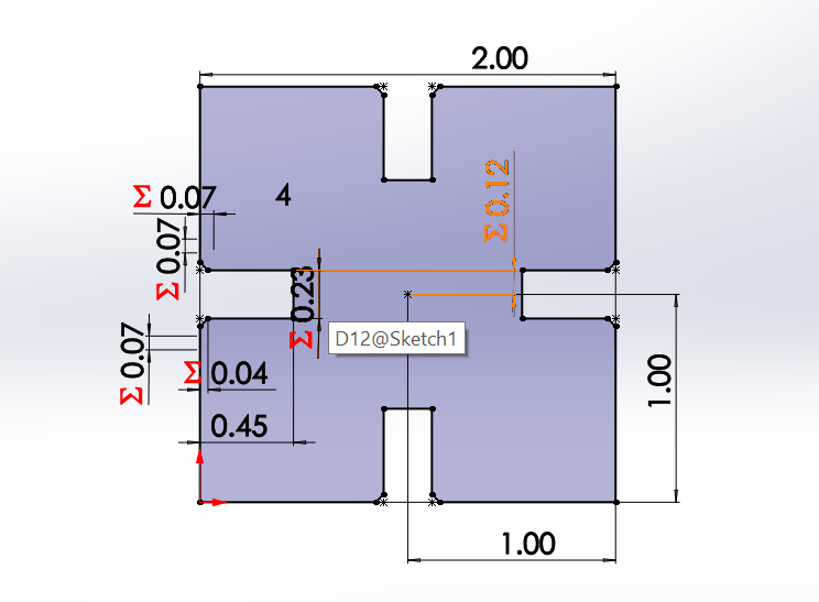
I began with a single square in a sketch in SolidWorks. I then set the chamfer size to be based on the slot size, making the complete slit parametric.
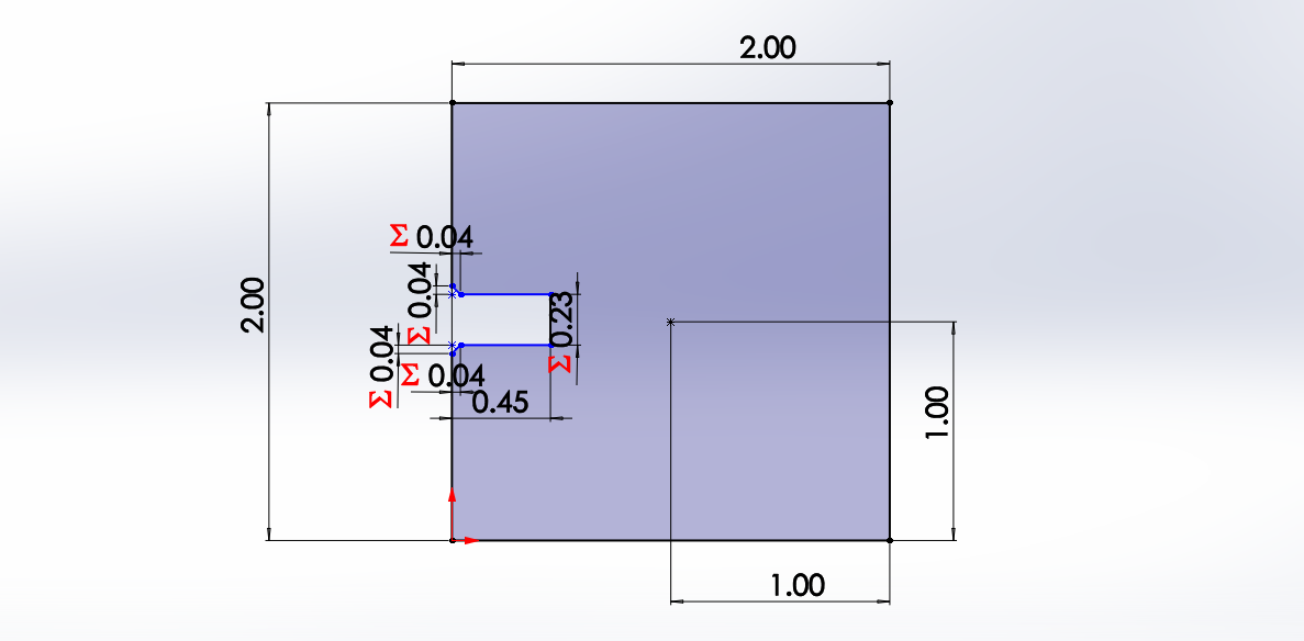
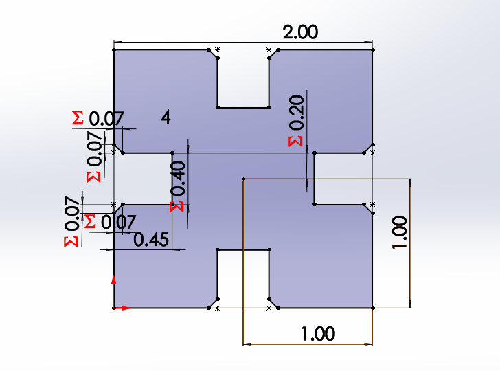
Then I rotated this slit around the square, making sure they all stayed related. After taking off sharp corners with a fillet, I had completed the first singular piece. Just as a test, I changed the slot size, and as planned, all the other slots changed with it.
Then I created a linear pattern, making a small army of them. Again, I tested changing the slot size, and every other slot in the group changed as well.
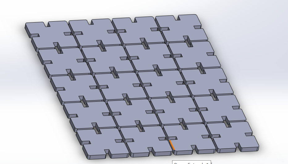
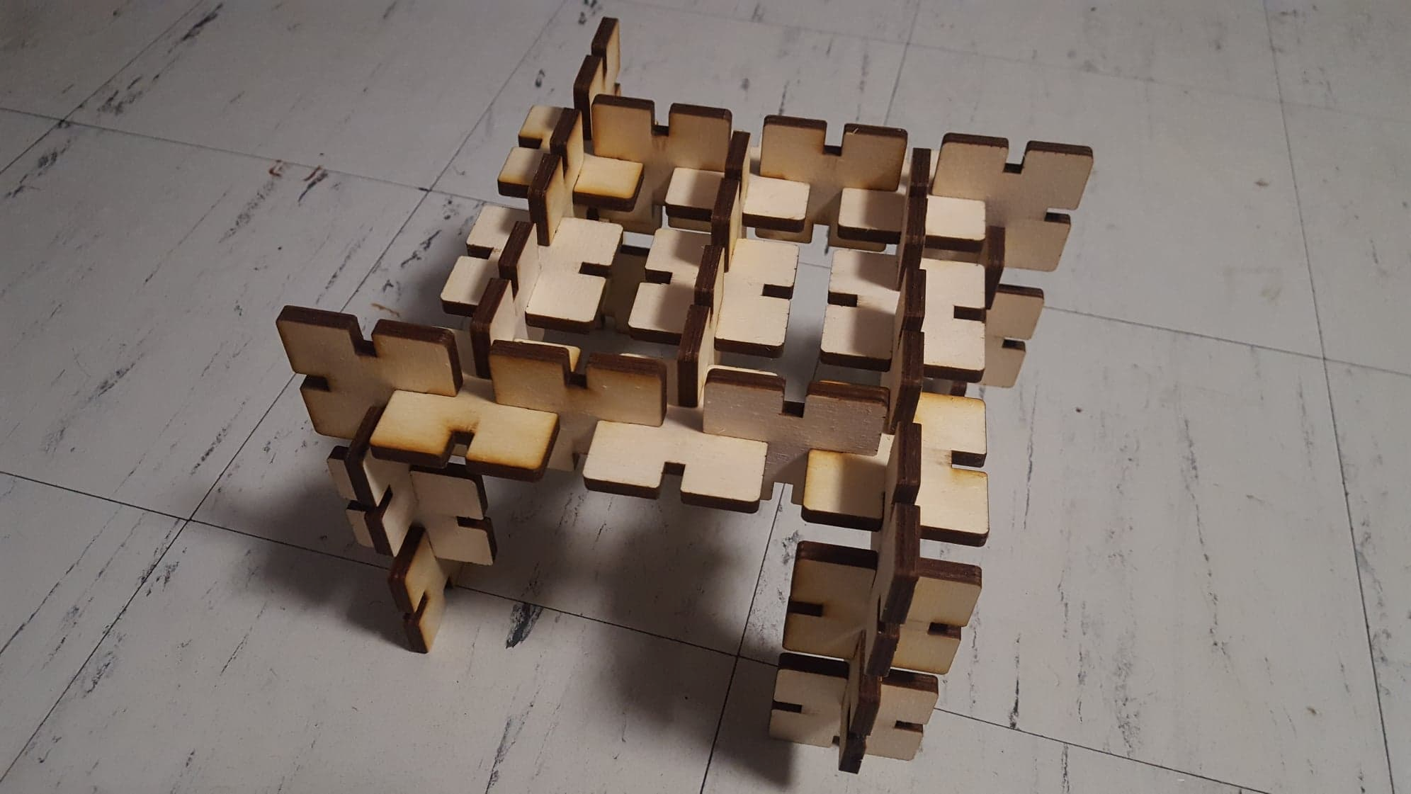
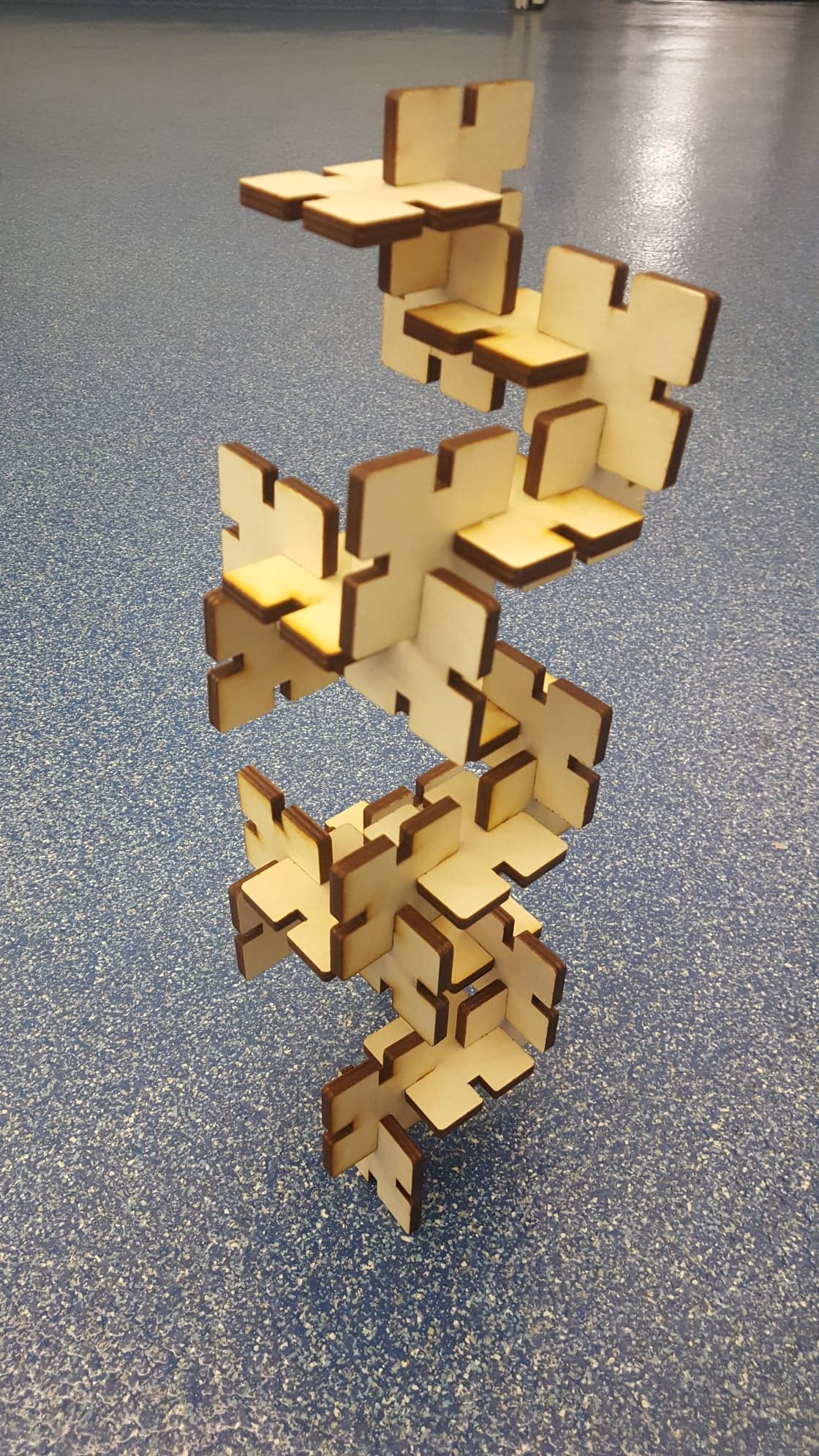
After one print where the construction blocks didn't come out clean, I cleaned the lense and boosted the power setting a little. The final result was some nice, snugg-fitting contruction blocks that could be creatively snapped together in many different ways.