Assignment 4
Electronics Design
This week, the assignment is use CAD to design a custom PCB board with added functionality relative to the board in week 2.
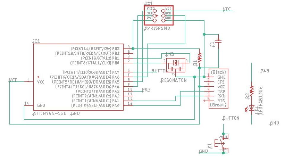
I chose to design my board in Eagle. There was a bit of a learning curve, but after some advice and some tutorials, it became relatively easy to create the traces. One thing I realized as I neared completion of my schematic was that I should definately mate components by name--not by drawing virtual conections. Even though I wasn't full consistent, I switched between these methods part way through, considering it would make my life easier and make the board easier to understand.
Next, I moved on to the actual trace design. After running some unsucessful auto-routing, I decided to move everything manaully.
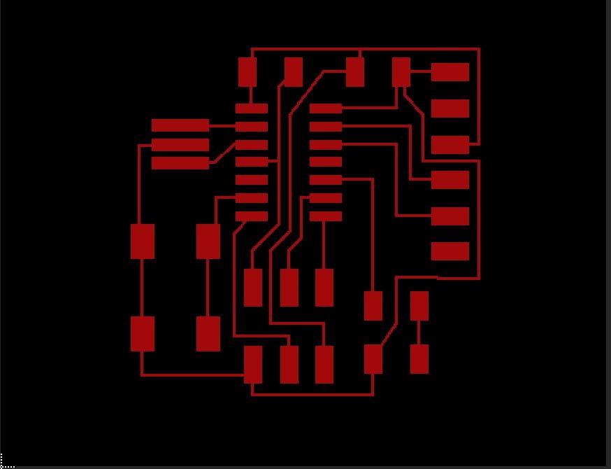
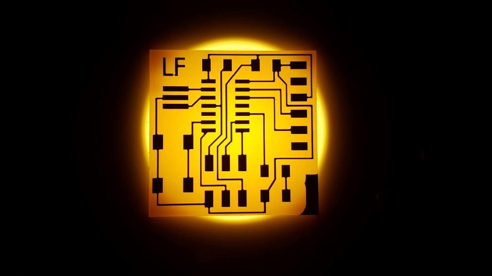
Once I had everything in place, I exported the traces and the outline as .png files. Upon PCB milling, I had some difficulties with zeroing and changes in DPI, but eventually I got it to work.
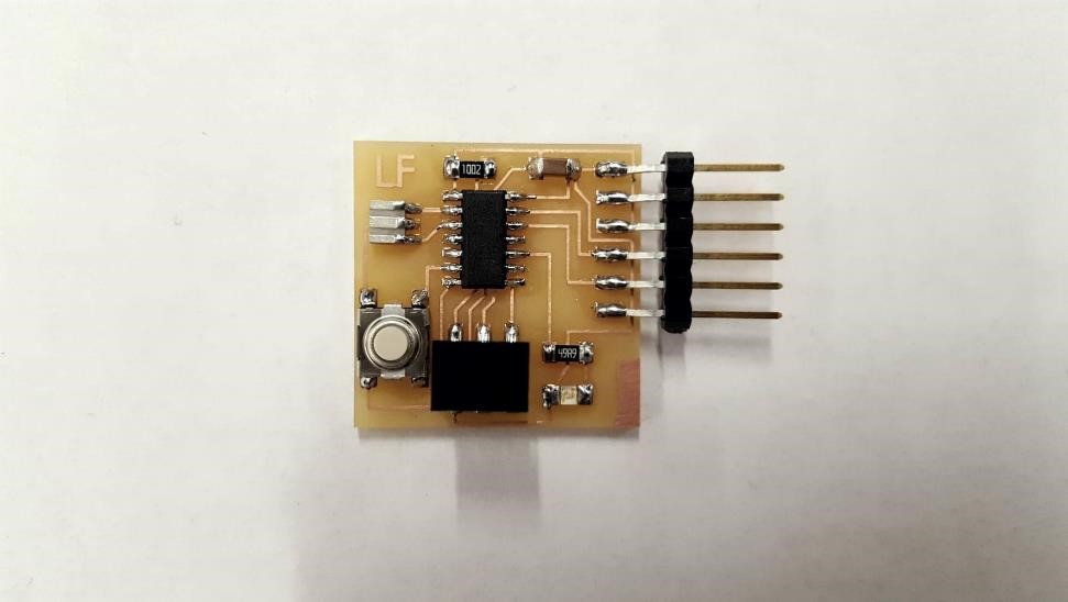
Then it was only a matter of stuffing to finish up the board and prepare it for testing. Setting up a simple interupt service routine on the button pin and setting the LED as a High/Low output had it working like a charm.