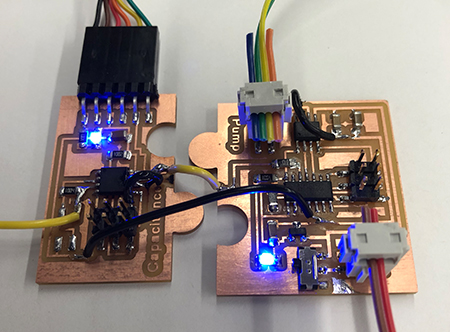
and pump
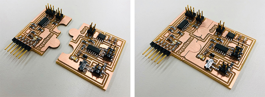
This during weeks 8 and 9 I was dealing with other deadlines, so when those came to an end I did those week's assignments at the same time. As I was working on them simultaneously, I also aimed to to design the circuitboards in such a way that they could easily be fit together as puzzle pieces and create an input-output connection.
Capacitance sensor
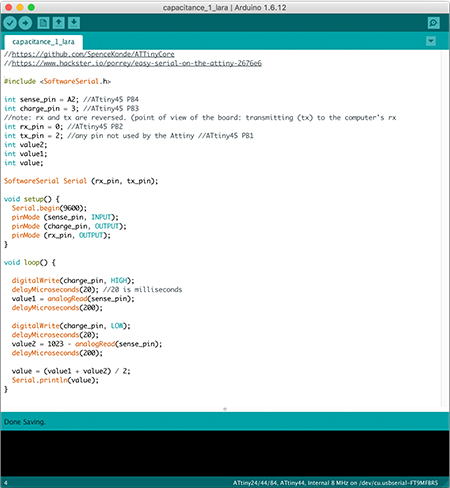
With my final project in mind I built a capacitance sensor using one of Neil's board designs for step response. I added an LED to indicate the board is receiving power.
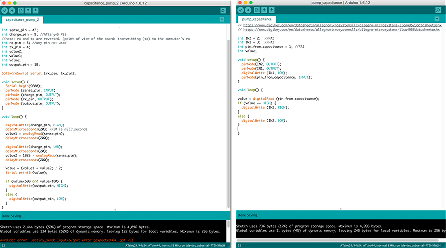
Getting the board to work proved a bit difficult: I made a couple of mistakes in my code that had to be sorted out. Important to remember is that the tx and rx pins are viewed from the perspective of the microprocessor (not the FTDI) and the receiving pin needs to receive an analog signal and thus be named as an analog pin.
The appearing spikes in the Serial Plotter still have an unidentified cause. Rob suggested multiple things I could try in order to figure out what is going on and to solve it: making sure the pull-up resistor is always 5V (and the microprocessor is not accidently resetting itself), increase the baud rate, add more capacitors between V and GND, test the measurement without charging, use c code without the SoftwareSerial library. I have yet to try these out.
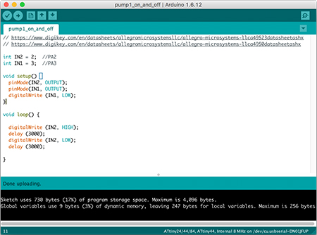
For the pump I used Neil's DC motor board, and added an LED to indicate the board is receiving power and a switch to turn the power on and off. This board and the code worked immediately.
Then I proceeded to join the two puzzle pieces. Even though I left a small gap between the puzzle pieces in the design of the board outlines, it was not enough because the pieces did not fit together. I also forgot to join the grounds of the two boards in the design. To solve both, I added some jumper wires. Connecting the two also raised the question of using the same trace that connects to the header's rx pin to send a value to the attiny of the motor board would work. In addition, the capacitance board failed to program, most likely due to some shorts that originated during the process.
So I decided to design and mill new boards to fix all of these mistakes. I exchanged the Attiny45 for a 44 in the capacitance sensor, to have a pin available to send signals to the other board. These new boards worked immediately.