Fast Forward
Programming
I knew going into the final push that I didn't really understand networking, and that it would be the hardest part. Thus, I allocated the majority of the remaining days to programming and debug.
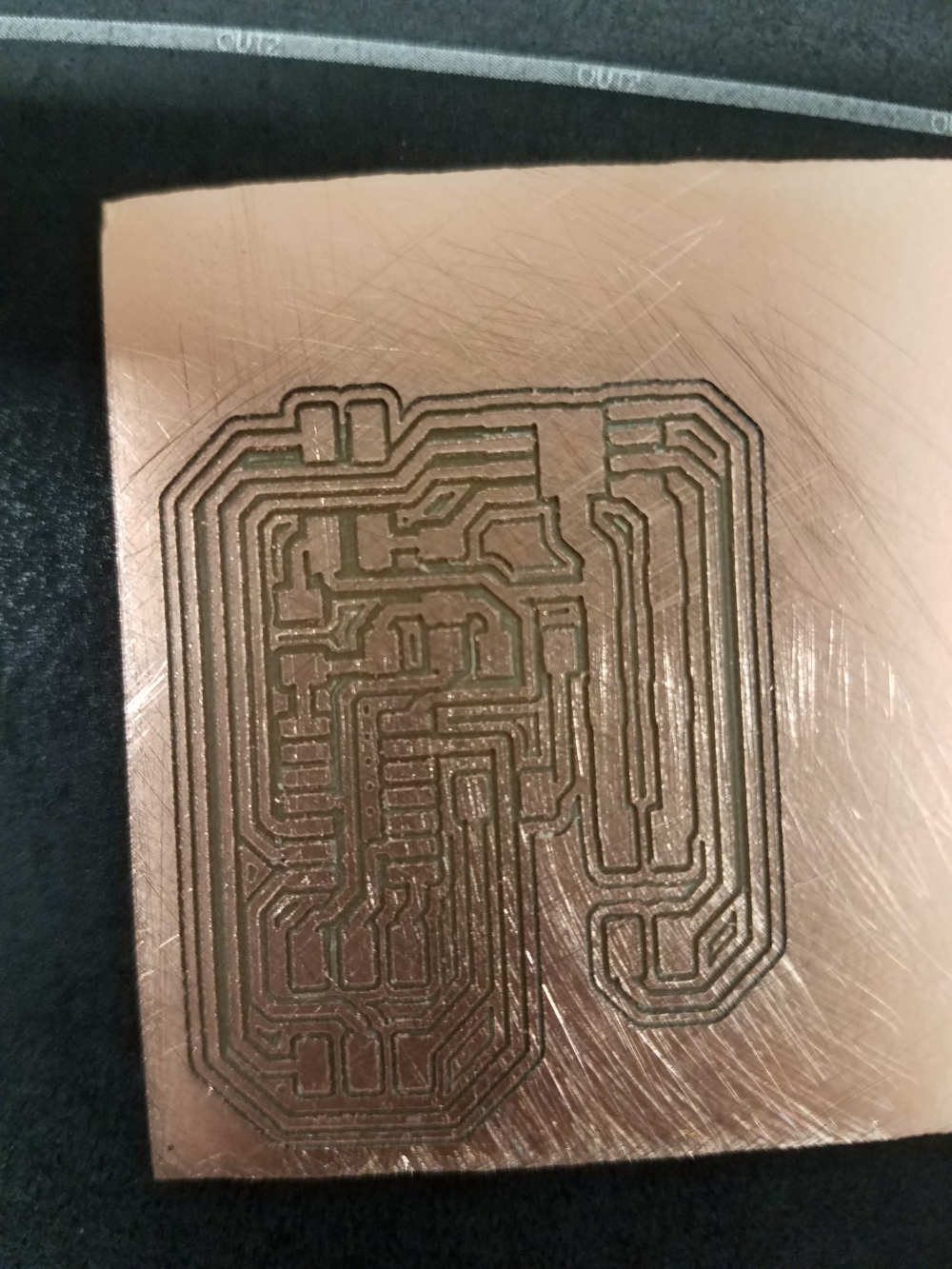
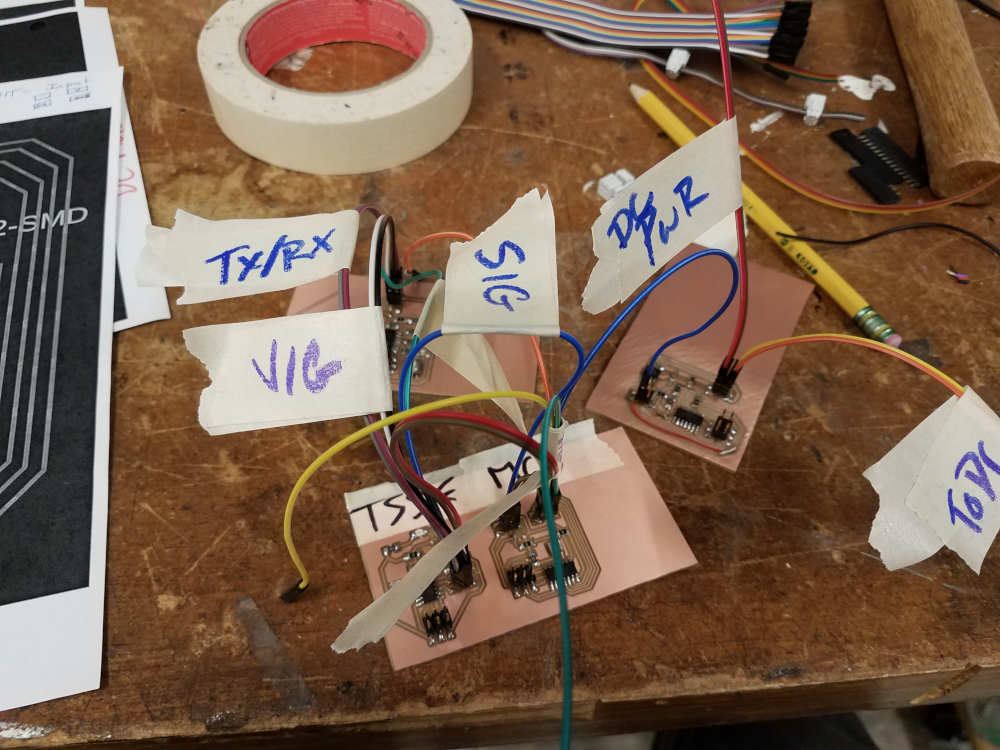
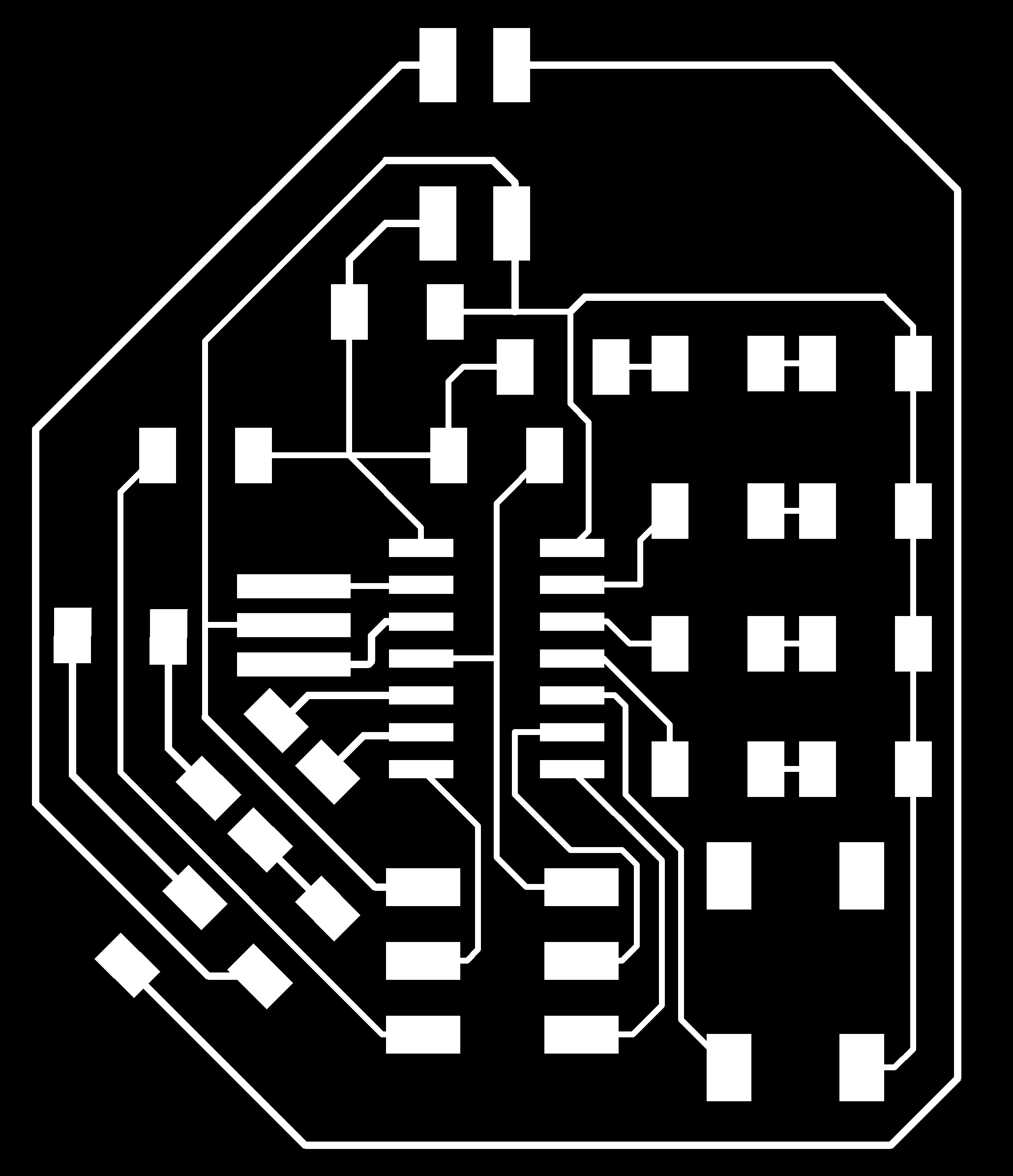
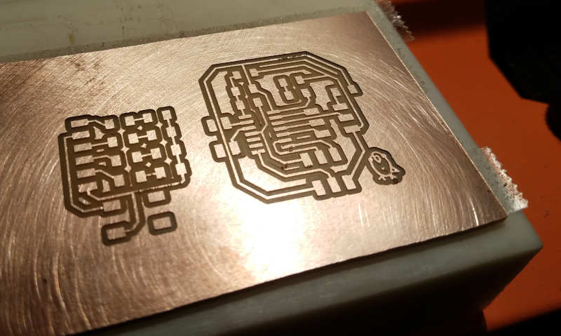
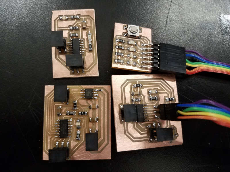
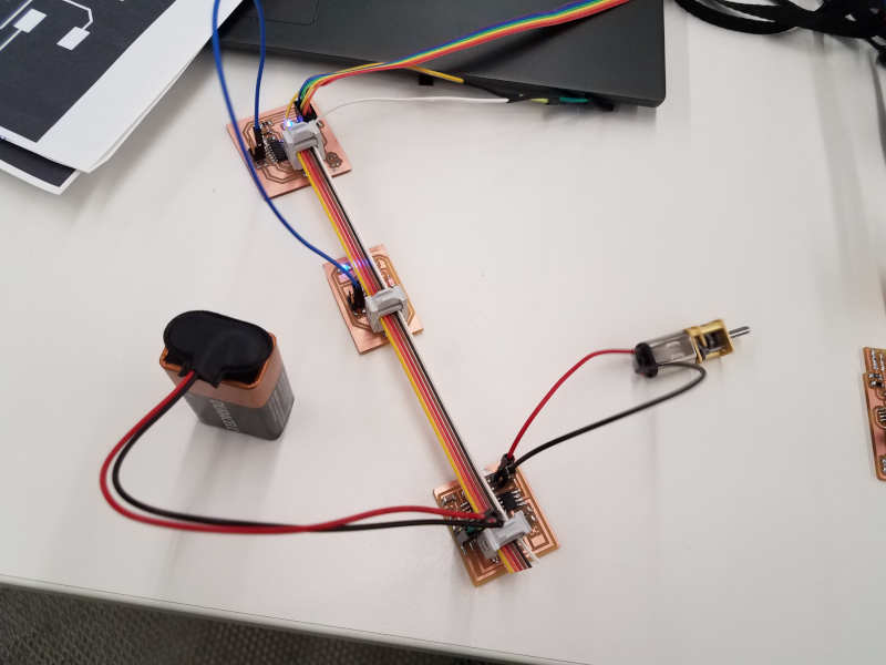
First, program the Button/LED Interface Board (BLIB). This board is supposed to take the button-press input, and translate that into an output that the next board can read.
The button-press program that I found on the internet works great. No problem there, and the board clearly takes it.
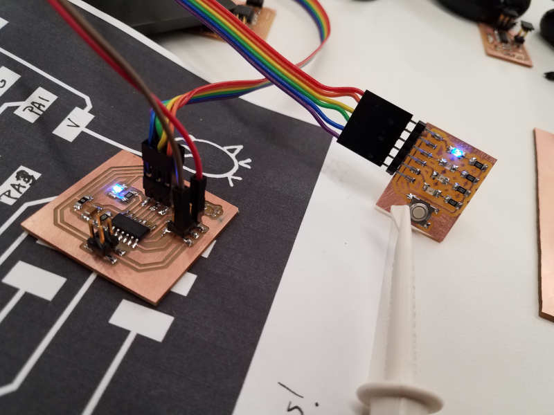
However, incorporating the network transmission is giving me trouble. First, I tried to see if I could send a "HIGH" over my TX pin, just for proof of concept. But when I added that to my code, every time I hit the button, both the RX and TX pins would go high. So I played with that for a while, and realized that I had my RX/TX pins backwards in two or three different places - and that I had set them opposite input/outputs. Yep.
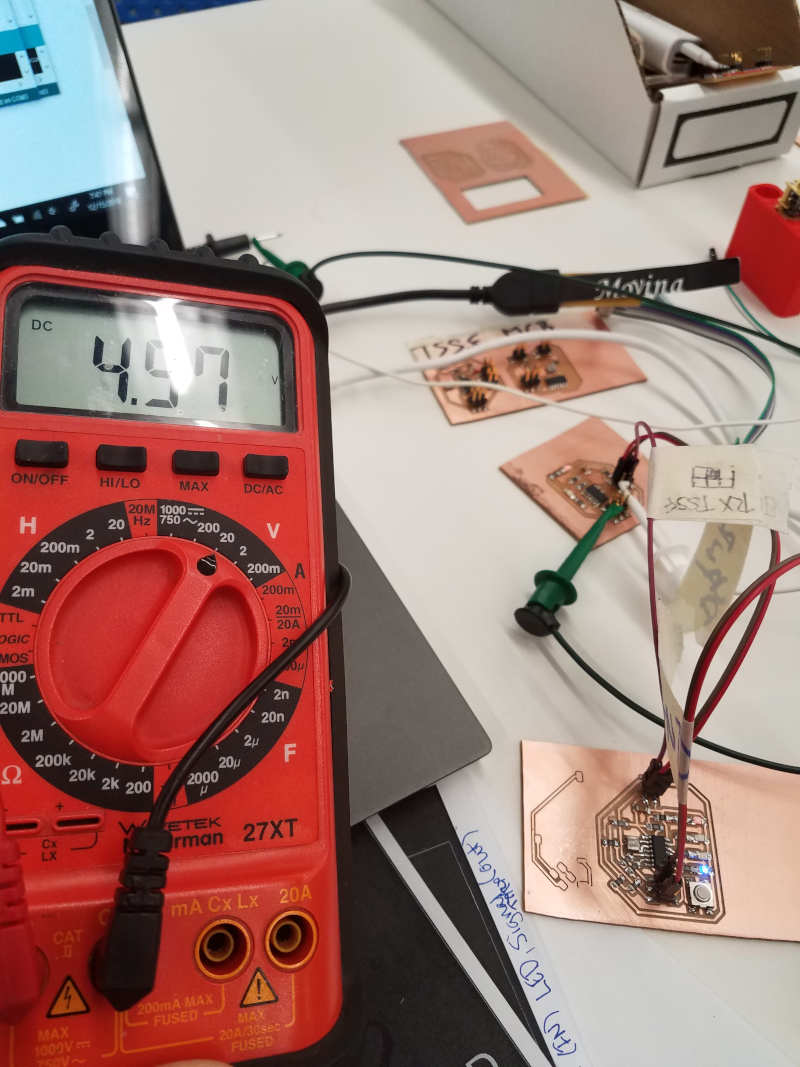
Once I got a consistent HIGH output on the BLIB TX pin, I tried to get the TSSSF board to receive the input. I used an LED on Pin 8 to debug. I wanted the light to go on when a signal came in on RX. However, no matter what code I used, the damned LED kept blinking.
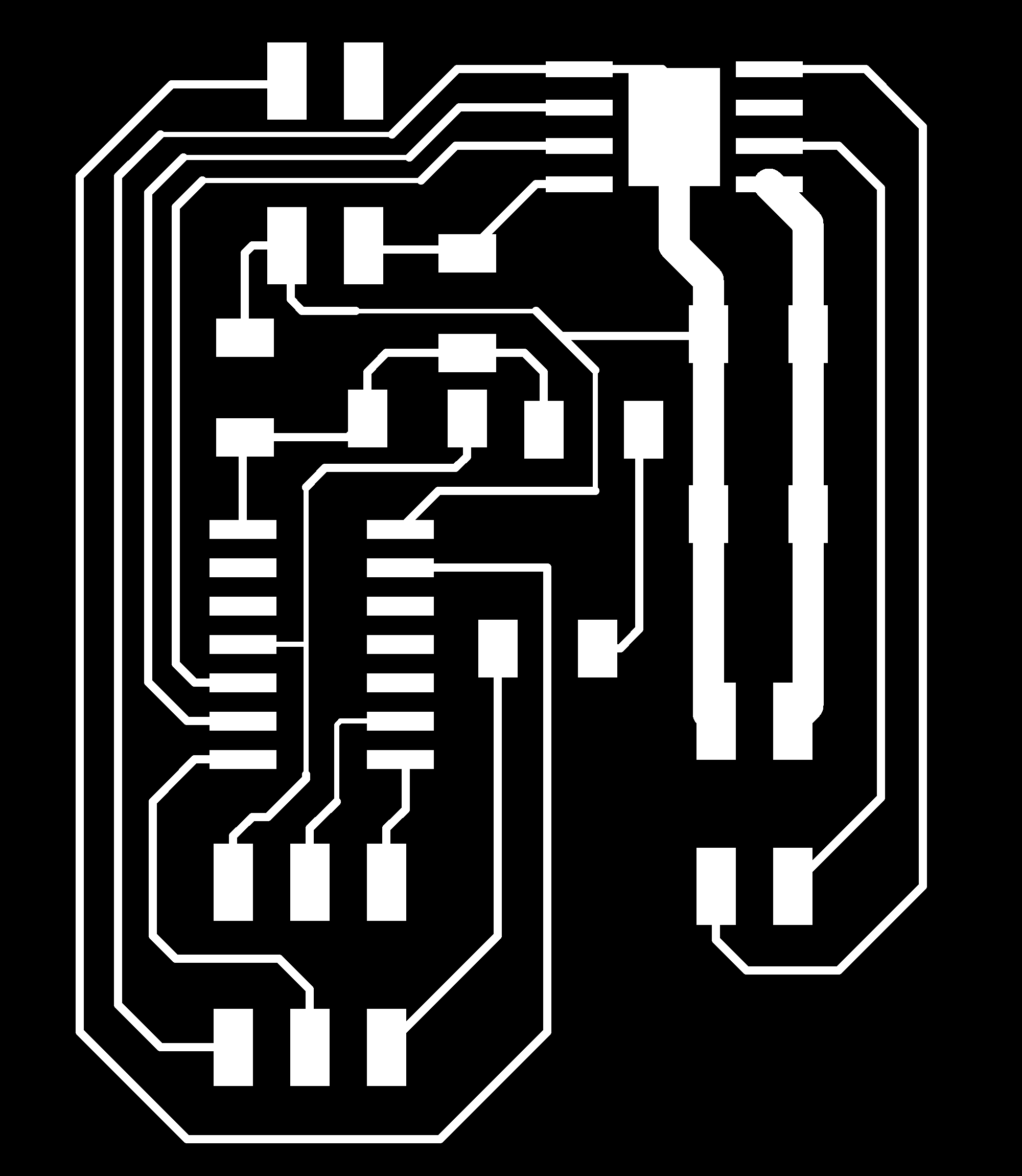
Next, the Timer Start/Stop, Solenoid Fire board (TSSSF). This board takes the input from the BLIB, starts a timer, sending a "HIGH" out to the Motor Choice board for the duration, and then, when the timer stops, sets output to LOW and fires the solenoid.
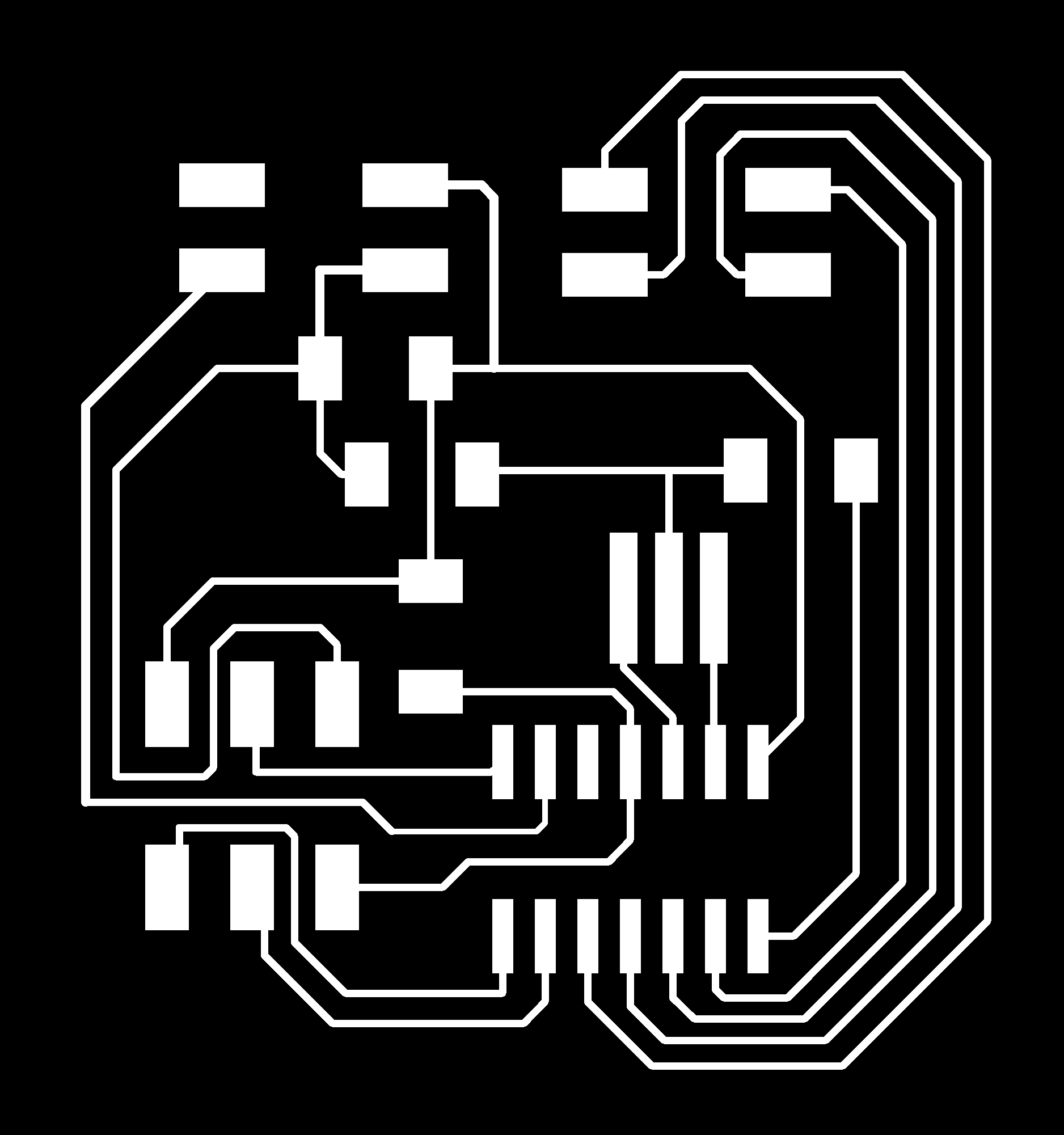
Then there's the Motor Choice Board (MCB). This board takes input from the TSSSF, chooses a random motor (1-4) to send a "HIGH" signal to, and keeps sending a "HIGH" to that motor until its signal stops.
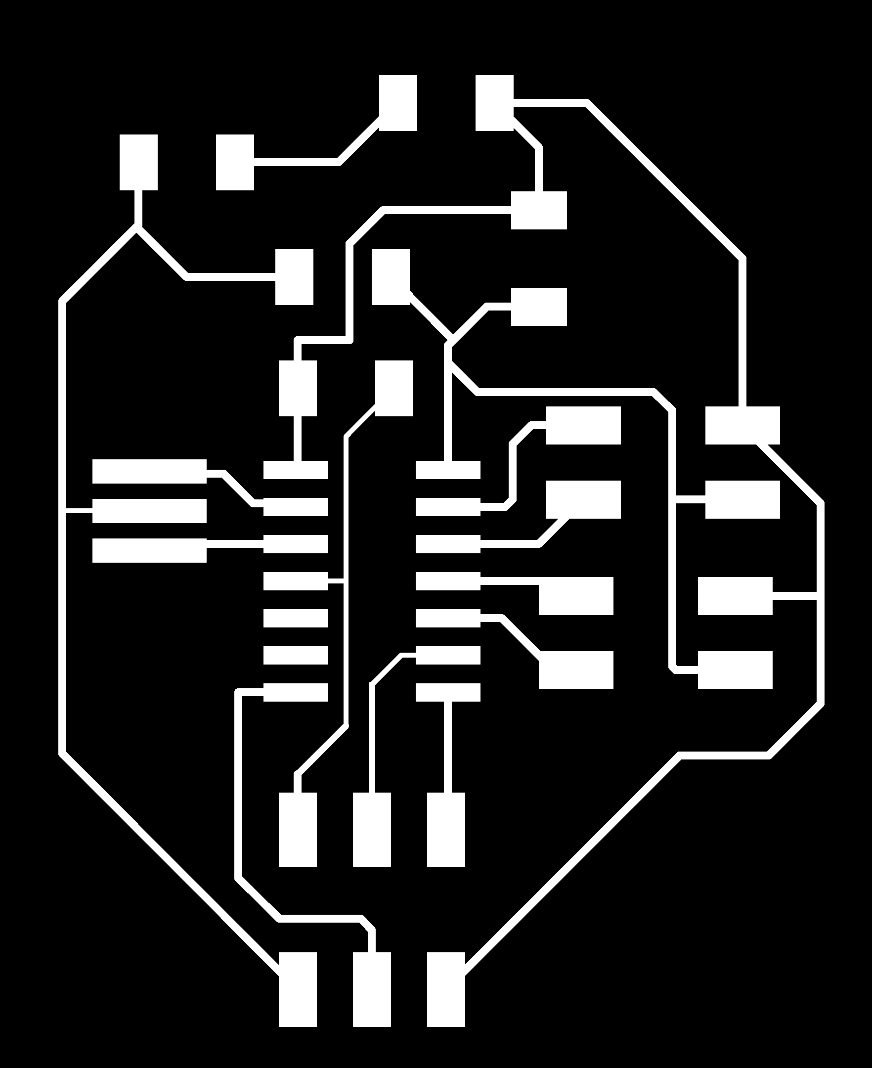
Finally, the DC Motor board, which doesn't need an acronym. This just turns on/off the DC motor when it gets a high/low.
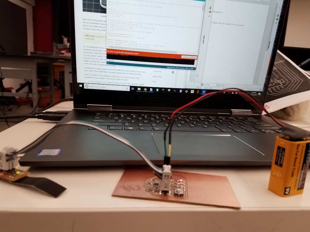
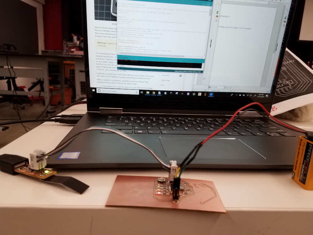
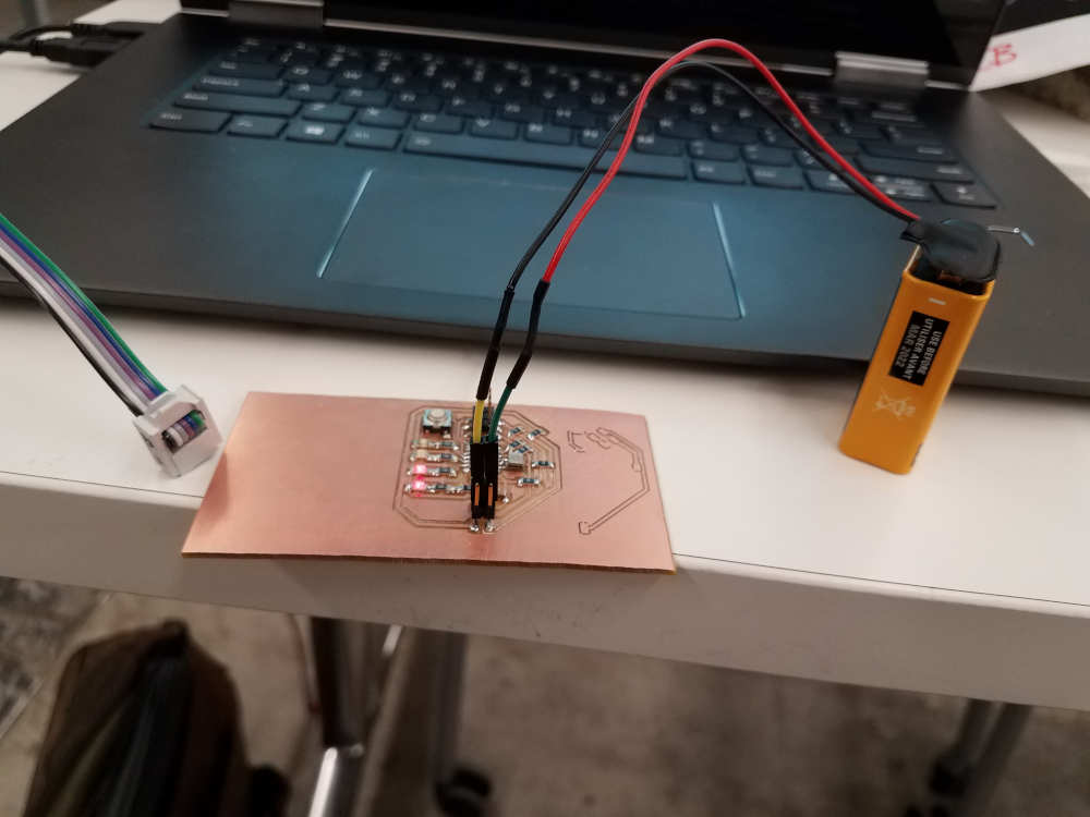
Programming this board took some finesse; I used a tutorial that Rob put together a few years ago as the basis of my board. Once I got it going back and forth, I was pretty quickly able to figure out how to get it to go in just one direction - and then from there, to slow down to just a tick.
At about 8 PM on Saturday evening, as I was entering hour 7 in the lab, I realized something. After reading so many kinds of tutorials, and so many different bits of code - somewhere along the line, I learned to read it. When I found myself unable to figure out what the tutorial was trying to say, I thought: just look at the code - and I did, and guess what?! I figured it out. You guys. I'm starting to understand how to read code!
3D Printing
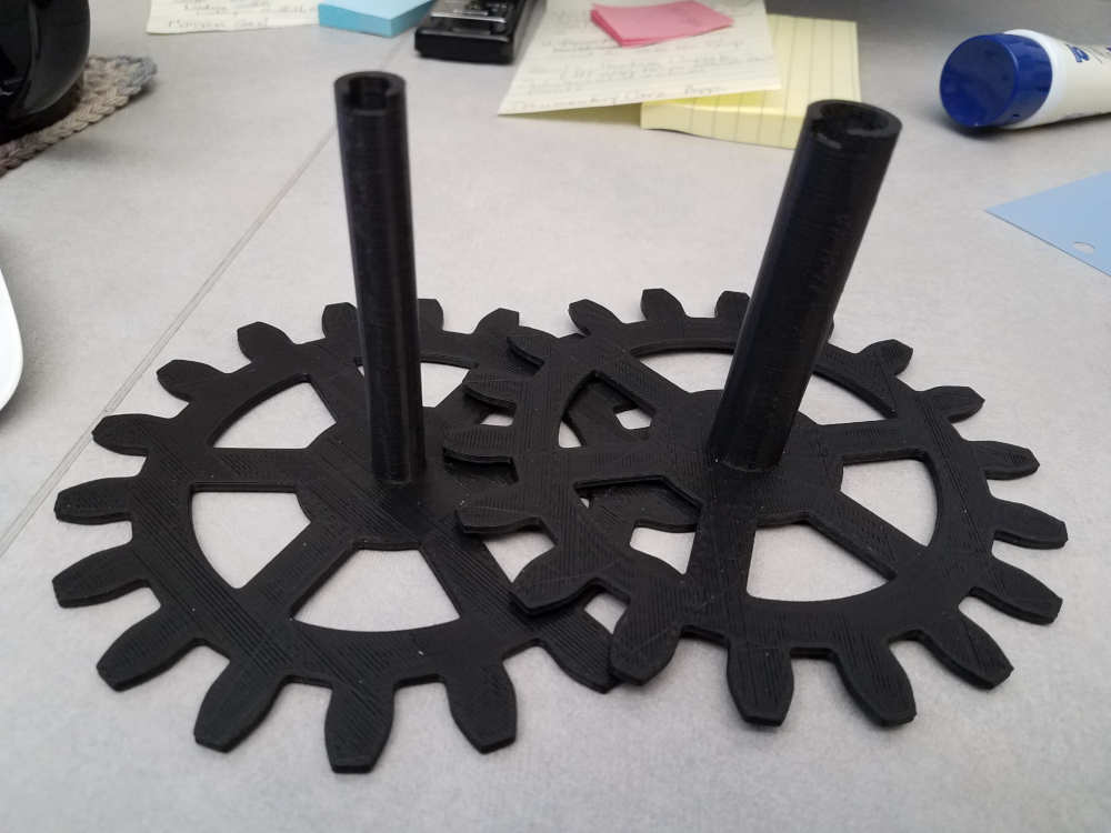
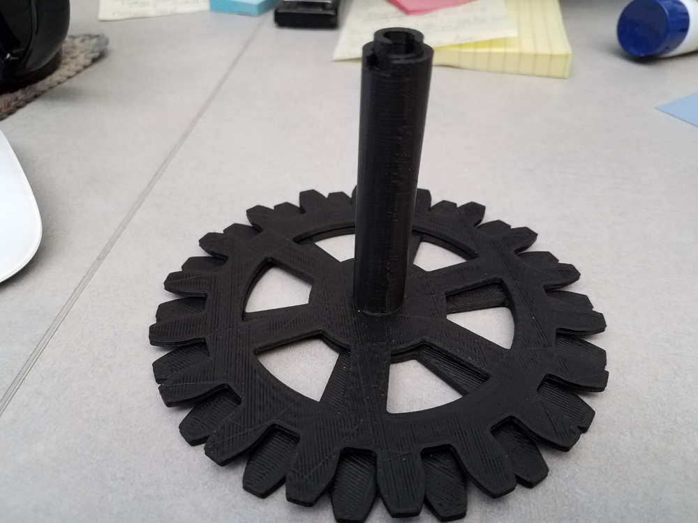
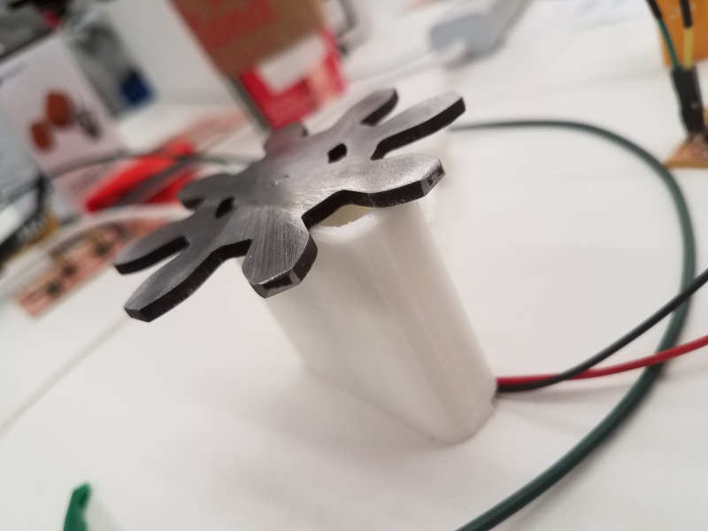
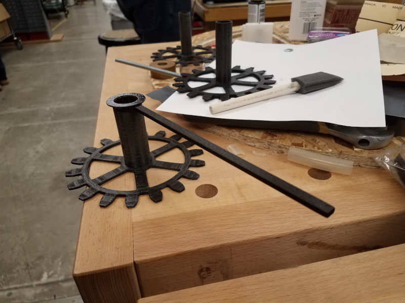
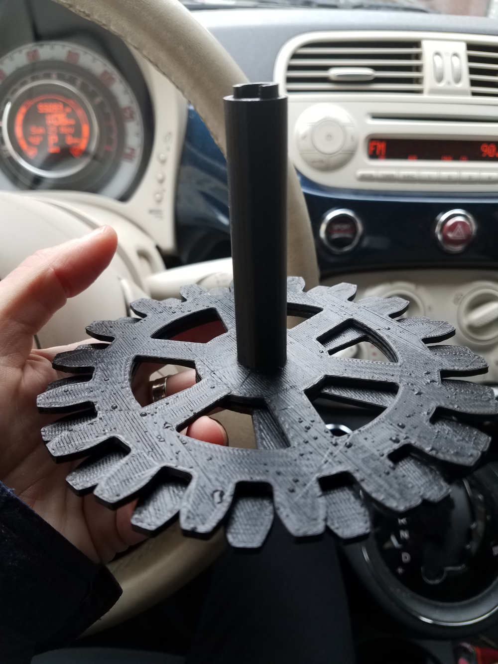
I've decided, for the sake of time, to use the 3D-printed gear axles. Unfortunately, early in the project when I was certian I'd have more time, I allowed my nephew, age 6, to play with the Hour and Soon axles I had printed to test. As a result, they were slightly warped. I took advantage of the Makerfleet printers to print the Soon and Later hands with hopefully a better resolution than the Sindoh gave me; sure enough, they came out quite nice.
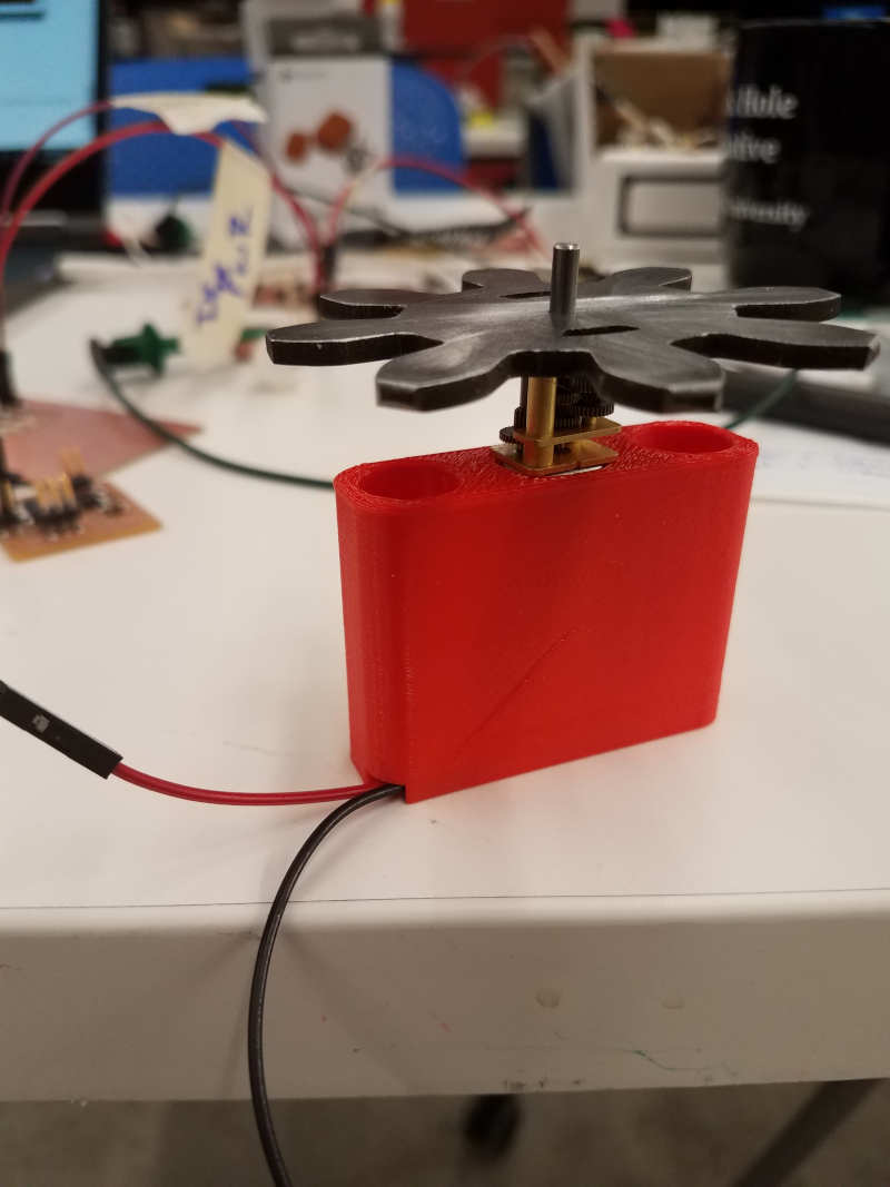
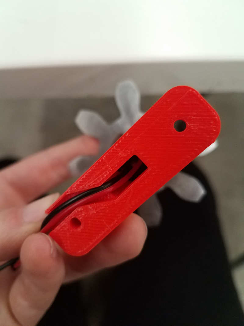
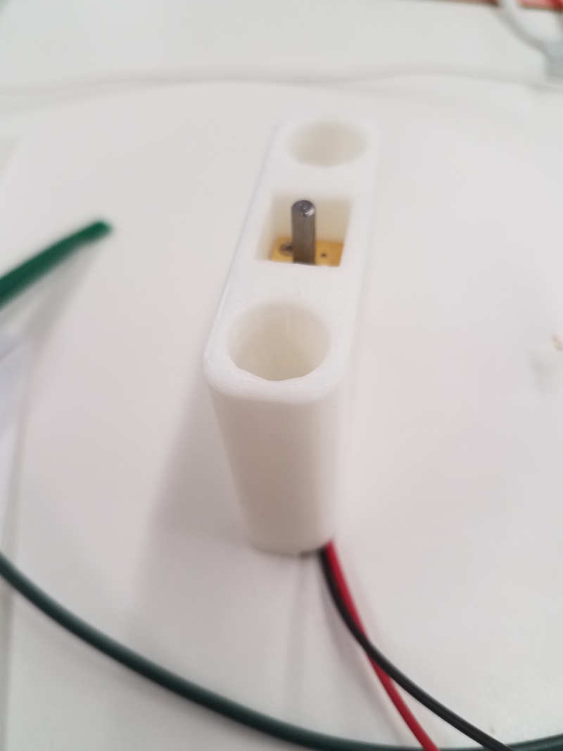
I also realized that if I wanted my DC Motors to be in the exact right spot, and secure, I had better figure out some housing for it. I designed a pretty straightforward encasement, which will also help balance the gears (and, unfortunately, probably add a lot of friction).
In Version 1, I neglected to consider the size of the square part of the DC motor; in Version 2, I got a pretty good fit. If I had more time - but, alas.
Big Stuff
I'd like to be able to hide most of my components; I really only want you to see the gears. Maybe the battery if we have to. So I thickened the back structure supports to allow for a pocket, mirrored it, and will sandwich the electrical components in the resulting void.
Finishing
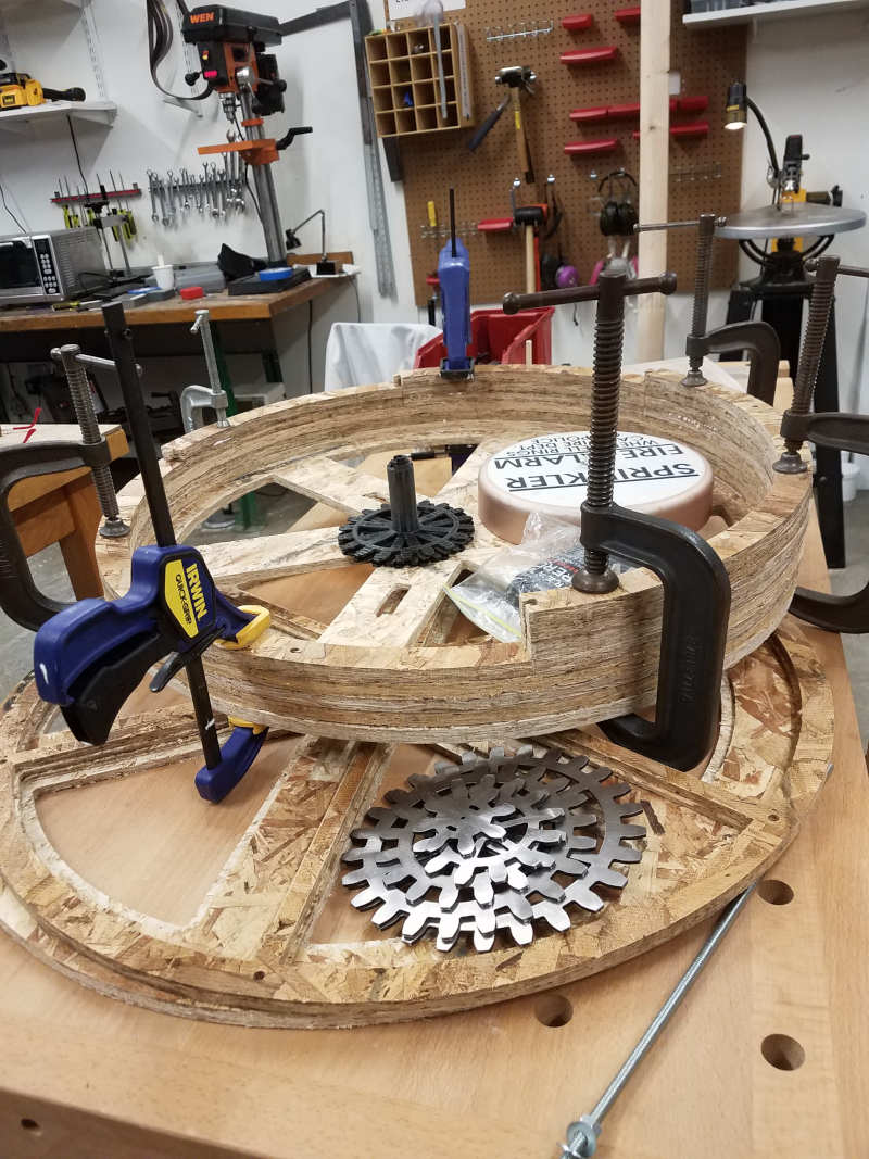
I quickly realized that I had made several errors in measurement throughout the design process. First, the gear axles are a total of about 3 inches tall. The gear stack itself is just less than an inch - which means that the bell, which overlaps the central gears, has to start at least an inch above the bottom plate.
Meanwhile, those fancy DC housings I made were supposed to go through two layers of clock board - but I decided to leave one detatched to allow for show and tell. I was going for the finished unfinished look for the final case, which bought me some time for other finalizations, but also made measuring a little trickier.
I wasn't able to get ahold of a good handheld sander, so the case is a little rougher than I'd have liked. So it goes. The gray masks it a little bit.
Details
You can't have a clock without hands - so I tossed together a hand using a piece of rectangular balsa and a conveniently-sized machine bushing.
I spent a fair amount of time sanding and smoothing the axles, but the outer finish is kind of crappy. I'm testing the enamel paint to see if that coats well, without adding too much thickness/tackiness.
Assembly
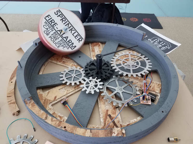
So I didn't actually put the whole thing together in its entirety until I set up for the presentation. I saw a few things that bothered me - there's a lot of empty space, for example, and the rungs of the clock case are much wider than aesthetically pleasing.
The motor runs. The hand spins. The button, my motor board, and most of my more ambitious programming doesn't work. But it IS a clock and it DOES NOT tell time - so I'm pretty well pleased!
Pulling Things Together
I spent a lot of Thanksgiving break finishing homework from previous weeks – 3D Printing, Inputs, and Outputs, specifically. All of these were components for the final project.
3D Printing
I’m pretty sure the best way to get the gears will be to use the Formlabs printer. I’ve asked Rob to acquire some of the Rigid resin, but Dixon suggested that I make sure my model is correct – check scale, tolerances, etc – using one of the quicker printers. So I’ve made the Hour and Now gearshafts.
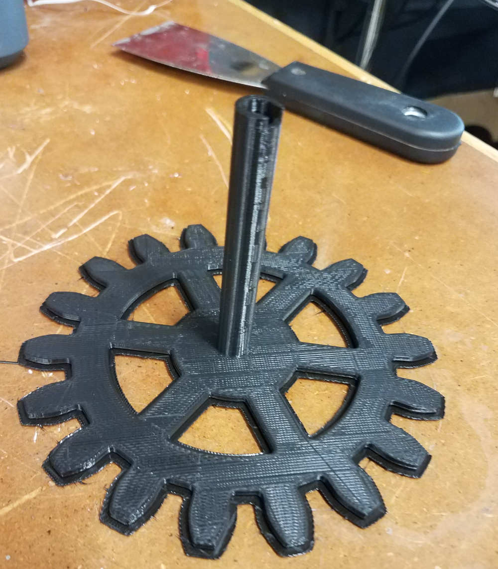
Lemme tell you – getting the gearshafts to nest together nicely, with cut-outs and fillets wasn’t super easy. Fusion 360 is pretty finicky, and/but it was a great learning experience. I’m pretty pleased with the model!
Inputs – Button press
I couldn’t program during Input week, because the power source I’d brought home to power the board while I was programming was a 6v source – and my board was built for 5v. Hence the overheating I mention in Input Week!
In the meantime, though, I came across this website: http://jmsarduino.blogspot.com/2009/10/4-way-button-click-double-click-hold.html. His code lights up different buttons based on how the button is pressed – he has one click, double click, short hold and long hold turn on a variety of LEDs. I was able to adapt this to my 3-light board, using only the one click, double click, and short hold.
Then I decided well, I do need to have a fourth input option – so I added back the long hold, asking it to switch on all three lights at once. Unfortunately, because the short-press happens before the long-press, the short-press light button goes on – and then when it hits the long-press time, the short-press light goes off! I’d really like to replace the long-press with three presses.
Outputs – Motors
I got new servo motors – ones which rotate 360 degrees. These worked pretty much as expected with the sweep code, just spinning around nicely. I don’t love them, though. They’re really loud! And I really don’t need precision angles, except in the 24-hour gear – but even that I’m willing to leave loose, mostly-right.
So I got a cute little DC motor also. I used Neil’s HelloWorld board and code, and ran into the same problem that a previous student had (http://fab.cba.mit.edu/classes/863.15/section.Harvard/people/Liu/outputdevices.html) the motor pulsed, softly at first and then just a bit stronger – when powered, but it didn’t rotate significantly. She removed the PWM measurements, so I did too – and sure enough, it spins freely. A lot too fast, so I’ll need to figure out how to slow that down. I did some additional reading through previous students’ work, and discovered a discussion here of PWM in Arduino - http://fab.cba.mit.edu/classes/863.15/section.Harvard/people/Basangwa/final.html – which probably has something to do with why it doesn’t quite work as expected.
Time Travel
I've chosen this week to start building the controller - the button sequence that will trigger the selection and start of timers. Somewhere along the line I've become comfortable designing and fabricating boards. Programming is another story.
The Story
Today I saw 1:08 AM three times.
This weekend was Daylight Savings - the time when large groups of people have agreed to change the measured time to a different measured time. Specifically, a time that already happened an hour ago. So it's usual, in large parts of the world, to experience the same "time" twice in the same night.
Well this weekend was a little bit different. I was out late at a show, and on the train home I saw the clock said 1:0x AM - and i thought, wow, that's late! I didn't think we were out that long - but we were having a good time so who knows?
When I got home my phone said 1:08 AM. I texted my date on Sunday at 1:07 AM, to say, well -
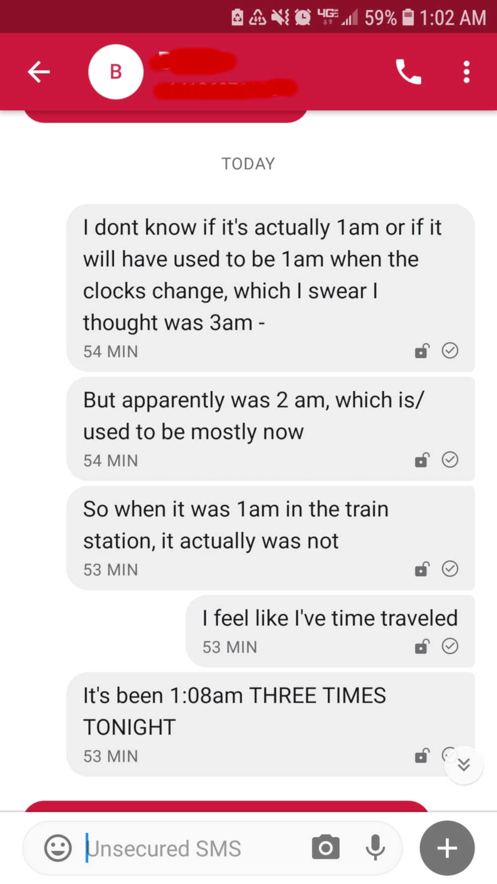
And now here we are again, at 1:08 AM - my kitchen clock says 2:29, which is probably* right according to yesterday,** and my phone and computer clocks match, thanks to the internet. So this, actually, is the second one (AM).
Except - I've already done this.
I experienced the thing before it happened. I had the joy, the wonder, the difficulty explaining it - just, an hour before I needed to.
*Mostly right. Partially right. Vaguely right. Eeyeah. Somewhere in that.
**Unless Jamie changed the clock.
Dude that's not time travel, that's a mistake -
Yes! Of course! But! I'm not after the fact of it - I'm after the feeling. I felt so joyful the first time - so confused, and honestly adrift the second -
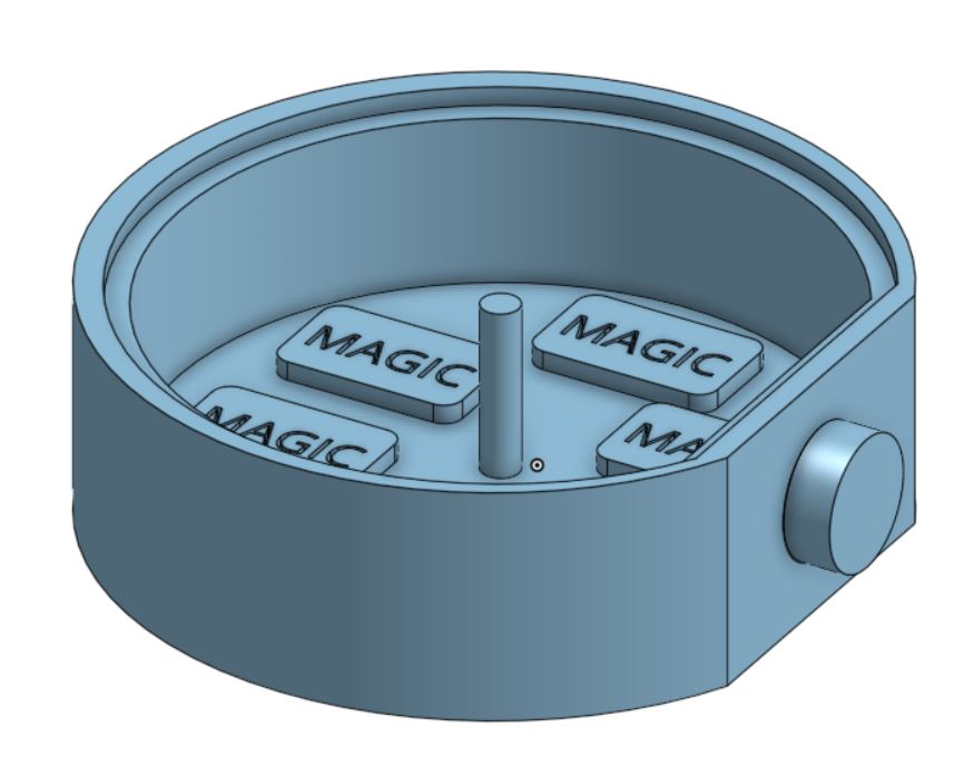
Adding the Magic
We've started working with embedded programming - which I'll need to use to read the button inputs, choose the motor, and activate the timers. More on the development of this programming soon!
Becoming Real
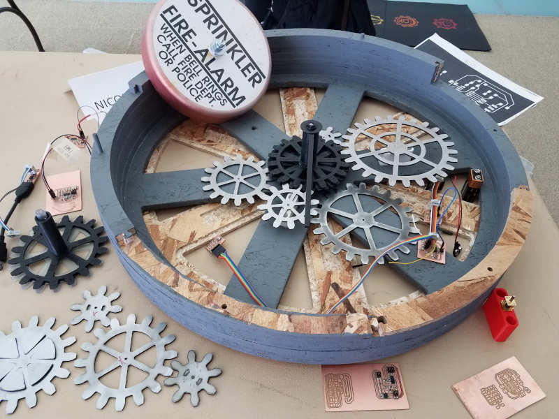
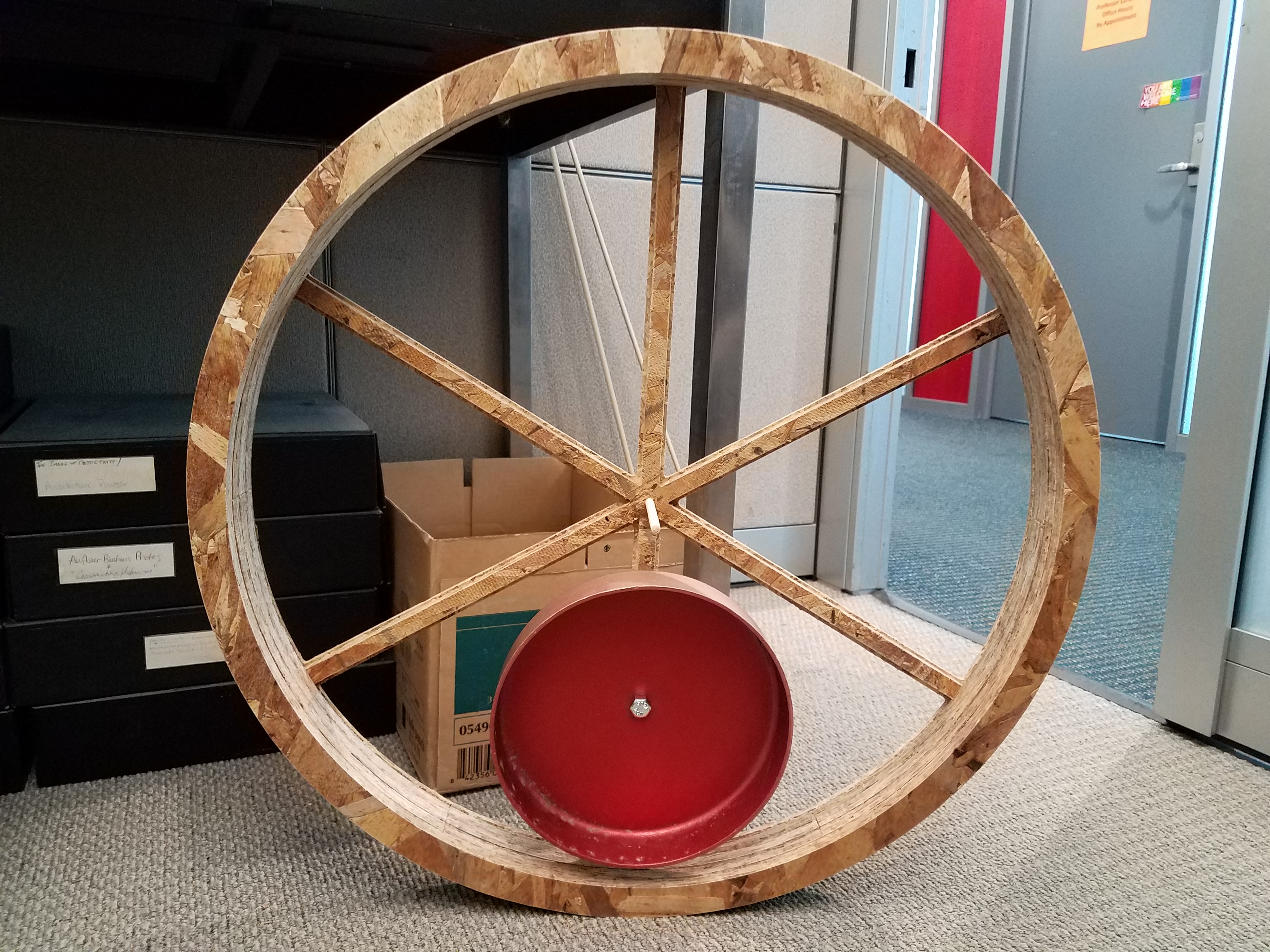
The concept of the clock is kind of silly. It's profound, in its way, but it's also kind of pointless. Definitely could be considered gimmicky. However, all watches, really, are kind of gimmicky. What matters is the style - what you do and how you do it. So I put a little more effort into the case than I otherwise might've.
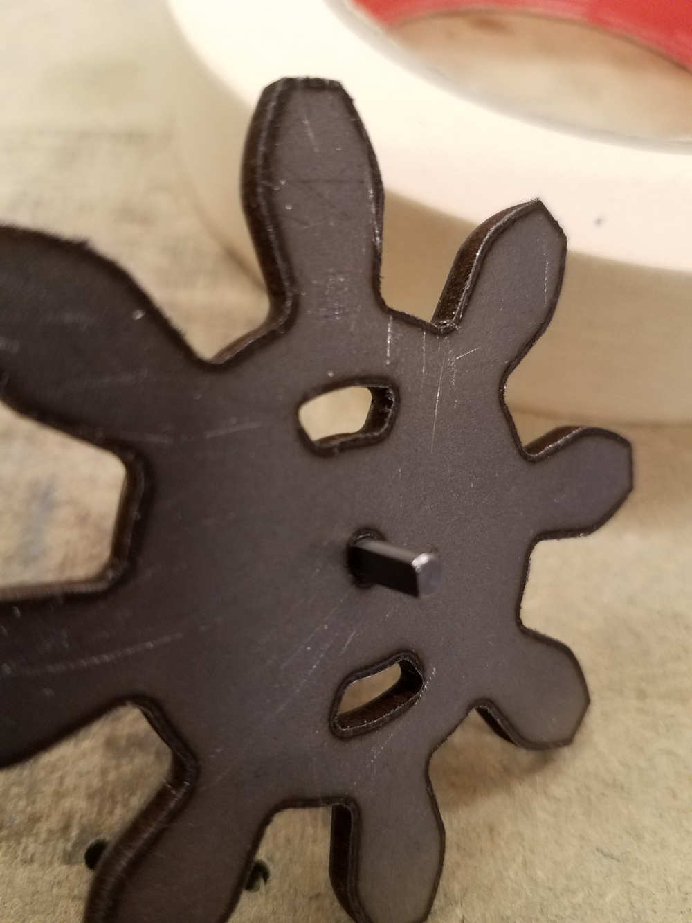
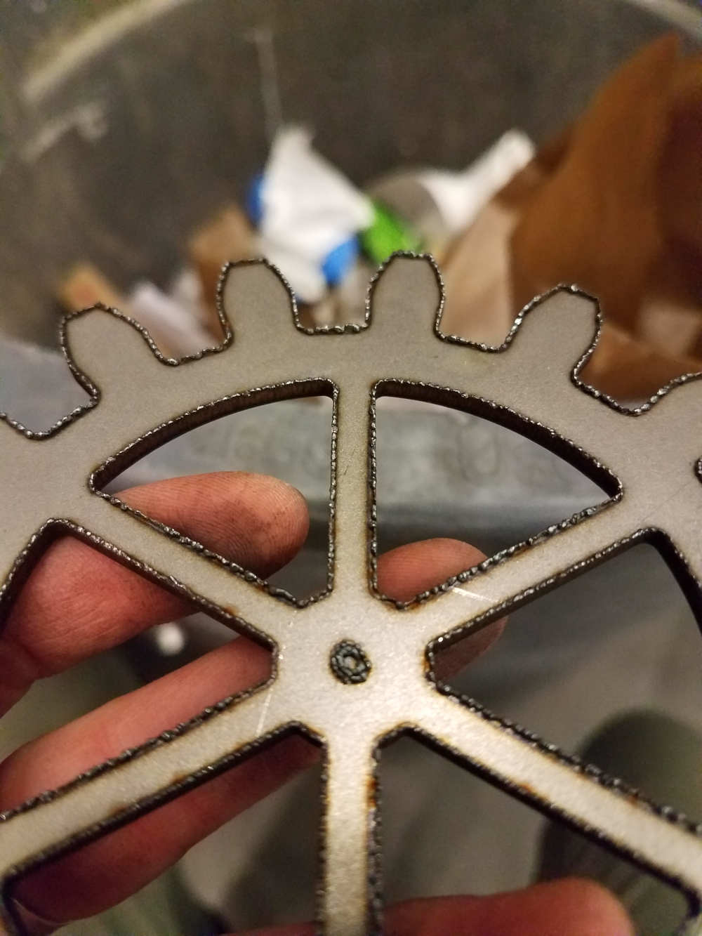
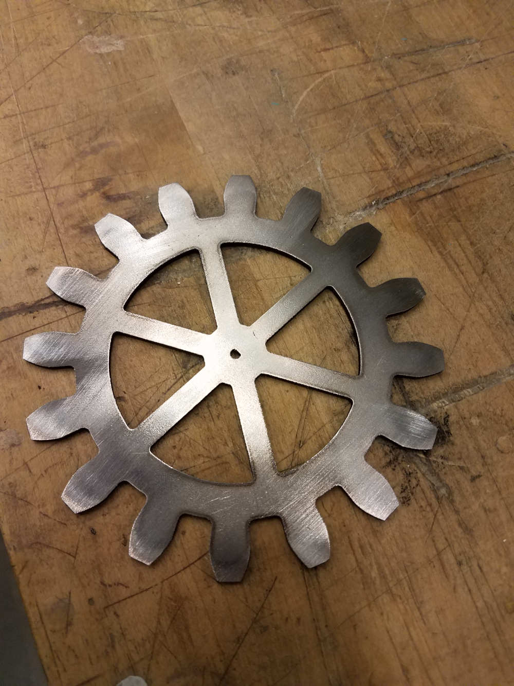
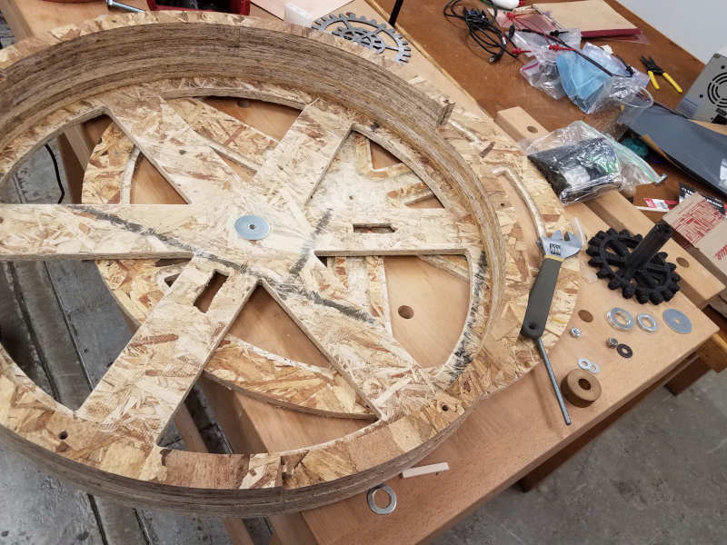
I cut six spokes into the back of the piece, like you'd see on a skeleton watch. Within the windows, I created a shelf - for acrylic or glass windows, should I choose to use them. I will want to have a face, partially just to give the main axel something to attach to.
A few things of note that I learned here:
- Plan for this ahead of time - when you're choosing the size of the spokes. (Or make them parametric.) Otherwise, the shelves on each side will end up lopsided.
- Cut out the inner windows on the INSIDE of the line, otherwise what started as a good-sized shelf will become just a tad too narrow.
- I may need to revisit the center diameter, and possibly the width of the arms, based on the materials I decide to use. The current measurements offer quite a bit of give, but this may have a lot to do with the material as well.
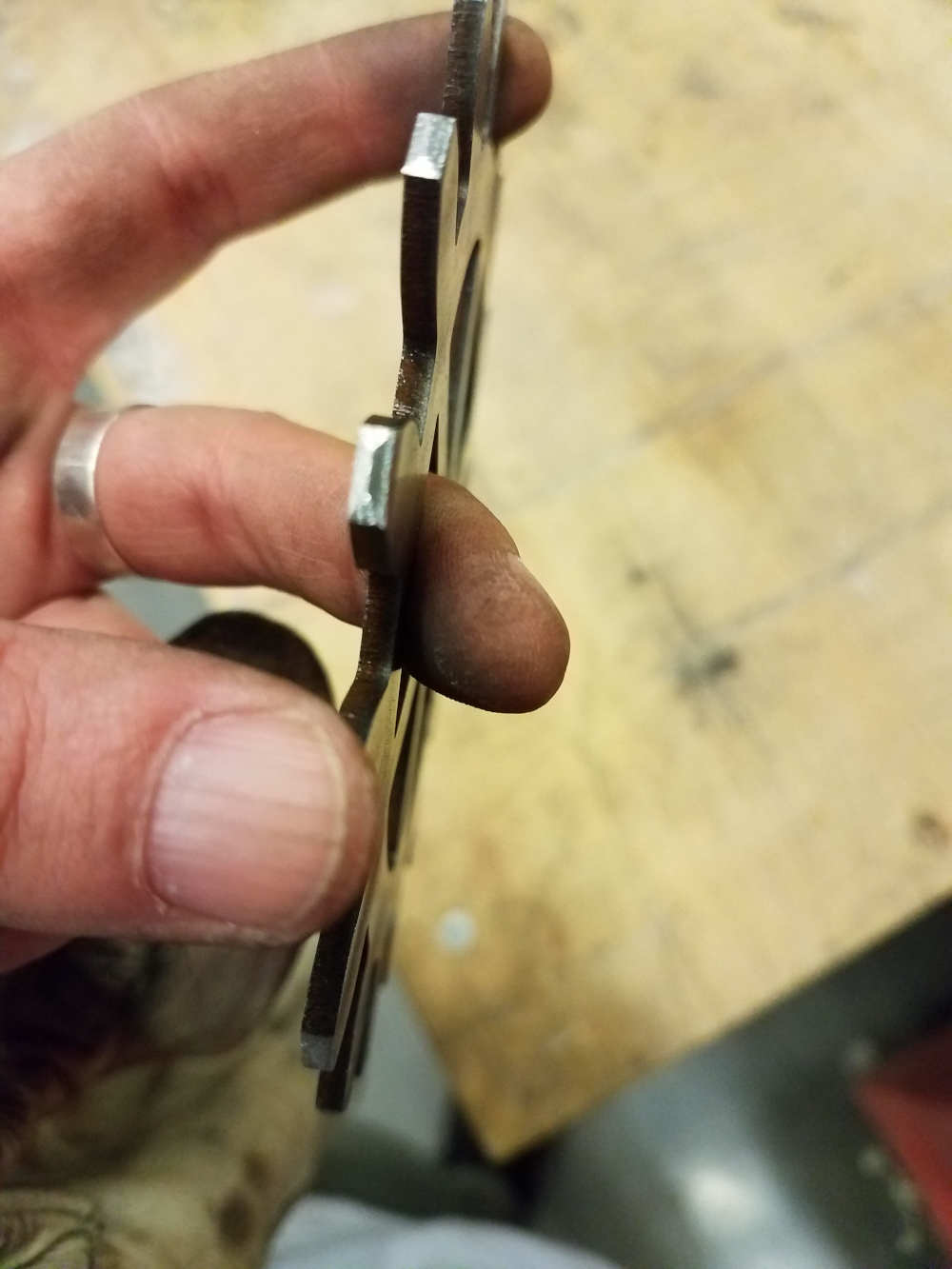
For the sides, I knew I needed more depth than I'd be able to get out of four layers of a complete circle - and honestly where would be the fun in that? So instead I made 60-degree arcs, with slots and tabs. Each arm had a 1/4-in hole, for a dowel pin that would hold each layer together.
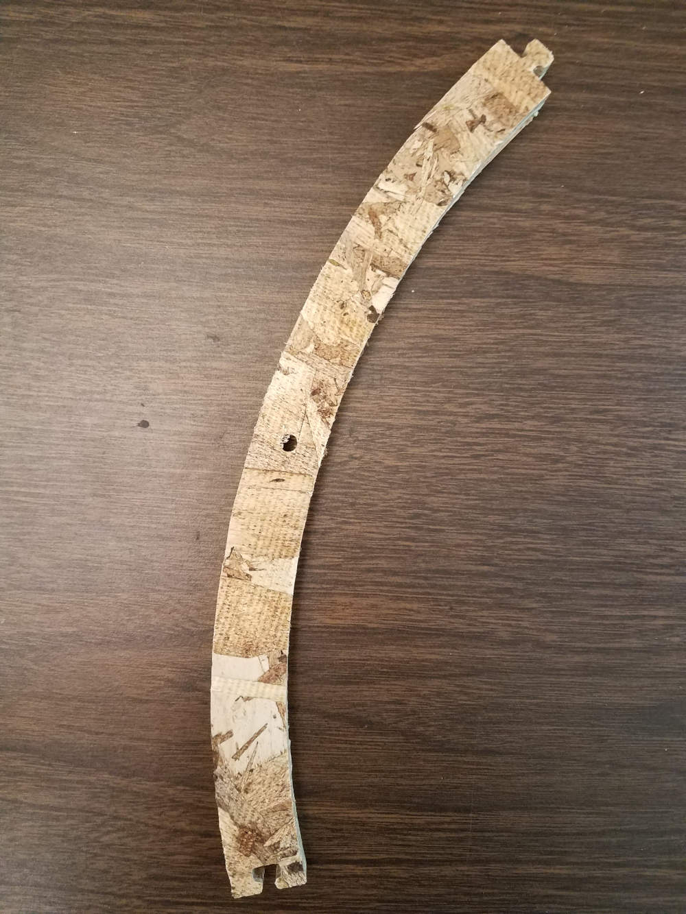
In this first version, I left the hole in the center of each piece. As a result, the sections are clearly visible in the prototype, and I expect would remain so even after finishing. I may stagger the pinholes in the next version.
Finally, the piece that will become the faceplate. This one has what Daniel called "blind holes" - holes for the pins to attach to, that don't go all the way through. I had meant to cut a shelf, too, similar to the windows on the back piece, but I forgot to plan for it in the cutting. It should have been the first cut I made, followed by a flip and the remaining cuts. Next time.
From outside
of time

I’ve started to think about the physical reality of the clock. What it will look like, what it will be made of. I have this really wonderful alarm bell, which I found during a hurricane* probably ten years ago. I wanted to use it for a different clock, the End of the World Clock, but I never really got that project off the ground.
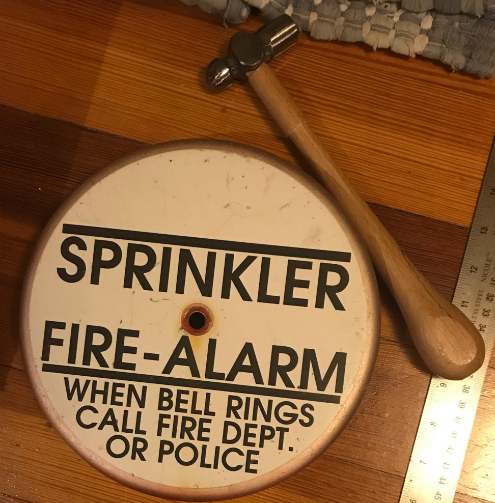
It’s an alarm bell. It’s meant to be loud. And it’s some kind of metal – maybe copper? – designed to be struck. When I ring it with a knife (which always seems to be the best and handiest tool available), man, that sound just keeps going.
So. I know I want this bell to be part of this version of the clock, which is really just a prototype for a watch. This gives me a number of constraints:
- Minimum radius (as there must be room between the hand shaft, mechanism, and case for the bell) - 9-11 inches
- Timers must be able to activate the striker
- Striker must have enough force (power) to ring the bell
And a number of things to consider:
- Bell mount – I will probably take a hint from cymbal mounts, and sandwich the bell between (light) dampeners
- Striker material – metal (steel, silver) sounds great, but what does a softer material sound like?
- What about a piano striker? What about a brush?
- Strike type – single? Bounce? Brush? Wham? What happens when you hit it with things!?
*Tropical storm, more likely, but hurricane sounds better.
End Week 3
Final Project
Not time
Let's play with Now.
Introduction
This clock has been in my head for years – as a watch, as an hourglass, as a collection of parts that move but might never ring.
It doesn’t tell you what time it is. It tells you when it’s time.
It has one hand and four timers. The smallest hand is a 24-hour clock, which makes only six stops: early, morning, afternoon, evening, night, and late. The others are window dressing, something nice to look at while time goes by – mostly so you can remember that a timer has been set.
Each timer represents an amount of time, randomly generated each time it’s set:
- The Now timer is a unit of time less than seven minutes.
- The Soon timer is a unit of time more than five, but less than twenty-five minutes.
- The Later timer is some amount of time between 45 minutes and two and a half hours.
- The In a While timer starts at three hours. I haven’t decided on an upper limit yet.
Timers are set by pushing the button. One click for Now, two for Soon, three for Later, and hold for a While.
Each click combo activates four actions: 1. The activation of a countdown. 2. The choice of path (hand). 3. The activation of a motor (which drives each hand at a particular rate. I haven’t decided yet if they’ll go at the same pace or not). 4. At the end of the countdown, the ringing of a buzzer or a bell.
Parts List (Estimate, Week 1)
- The case, which I will likely make out of laser-cut ply or 3d-printed plastic.
- The face, which I think this time I’ll leave clear.
- The lens, which I may still make out of glass.
- 4. The button.
- The first processor, which interprets the input to generate a number, and chooses which motor to activate
- (4) Timer motor processors.
- (1) 24-hour timer processor.
- (5) Drive shafts (motors?)
- 24-hour movement (2 gears, 1 hand)
- 1st hand movement (2 gears, 1 hand)
- 2nd hand movement (2 gears, 1 hand)
- 3rd hand movement (2 gears, 1 hand)
- 4th hand movement (2 gears, 1 hand)
- The bell processor.
- The bell motor.
- The bell movement (driver, spring, striker, bell)