3D Modeling
Electronics Design
Computer-Based work
Wherein we play fast and loose with the timeline.
Hey friends! This is where I am right now:

(And by right now, I mean sometime between three hours ago and some in(de)finite time in the past. Look, don’t worry about it.)
I’ll be back towards the end of the working period for Week 4, so while I’m in the woods/desert/outer space, I’ve made use of some of my travel time to get a jump start on the purely computer-based work of Week 3 (3D Modeling) and Week 4 (Electronics Design).
3D Modeling
So I spent the plane ride modeling the clock’s gear stack for 3D printing.
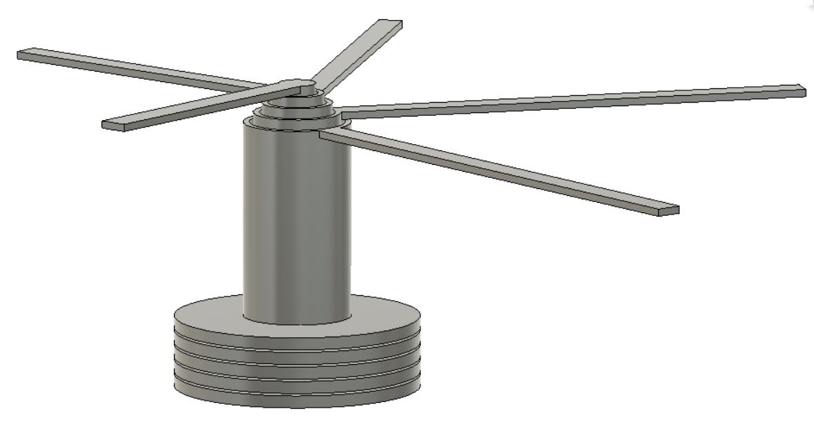
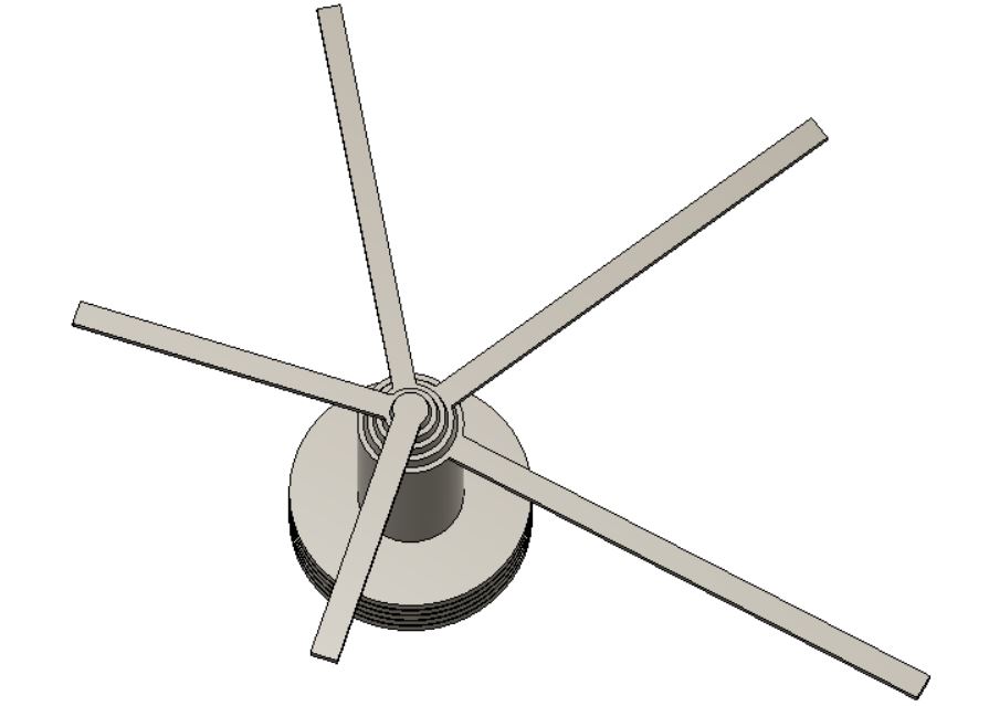
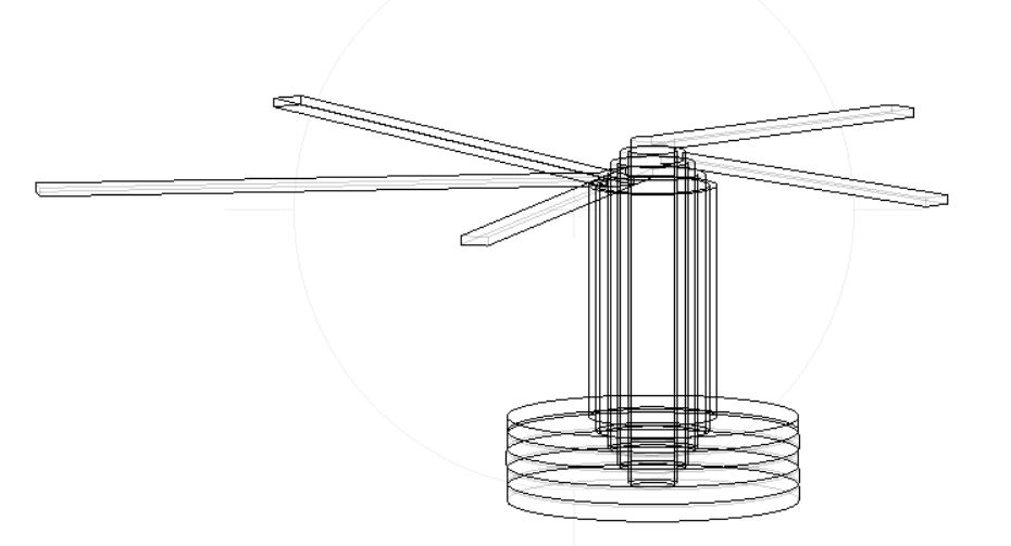
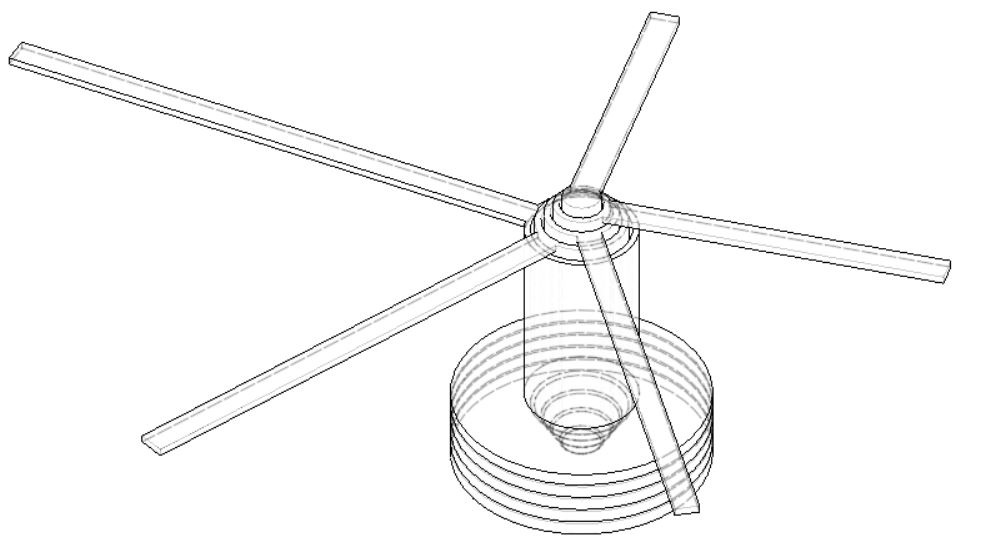
I’ve built it with a 1mm offset between each “gear” (which I’ve kept as a circle for the sake of simplicity) and hand, and a currently-variable-but-probably-about-the-same-distance offset between each tube. I’ve been told that you really only need to offset by about 0.5mm for pieces to stay separate, but since I’m working purely hypothetical for now, I’ll adjust once I get to a machine to parameterize. You can see it a little more clearly in the wireframe views:
I have a feeling, just based on seeing the way that material is deposited in a printed product, that this will not be the way I go for the final project. At least, the MakerBot and Sindoh won’t be – the Formlab might. It depends on how smooth the material is after curing; friction is not my friend in this component in particular.
Watches – particularly fine watches – make liberal use of sapphires. "Sapphire" is just the most common name for a crystal called corundum - it comes in a number of different flavors based on trace minerals, but the most popular forms (and relevant to watches) are your traditional blue sapphire, red or pink rubies, and clear. You might have a sapphire crystal "glass" protecting the face. You also see them used inside the watch itself. Sapphire is almost as hard as diamond (9 on the Moh scale), but much more plentiful – and can be grown in a lab easily, cheaply, and to a controllable fineness. These “jewels” (17 in a time-only watch, but as many as 40 depending on the number and type of movements) are carved out and polished into sockets, caps, rollers, and pins - and used to reduce metal-on-metal friction. Along with a tiny dab of lubricant, they create almost frictionless joints that allow mechanical and automatic watches to keep accurate time, and lose as little as 0.3 seconds per day.
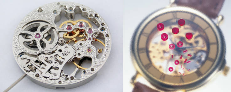
We don’t need that here. In fact, I actively do NOT want my clock to keep accurate time. That’s kind of the opposite of the point. However, I do want it to be durable, and not to break due to a mechanical issue that’s been solved for hundreds of years.
As an aside: Once upon a time, my partner got me a laser-cut wood clock to assemble. We had grand plans for using our snow days to build it – alas, that winter was pretty mild, and hand-sanding 2-inch long, 1/8-inch thick dowels (pins) is a major pain. It now gathers dust in the room of incomplete projects.
sad_clock.jpgIt did do one thing that I’m keen to explore with this project, which is that it used graphite (literally in the form of pencil lead) as a lubricant. Since I won't be using metal or jewels in this project, graphite should be a useful tool.
Electronics Design
So. Eagle.
So far I've worked through the tutorial - then lost access to the internet. Working through Eagle's official tuturial, I built:
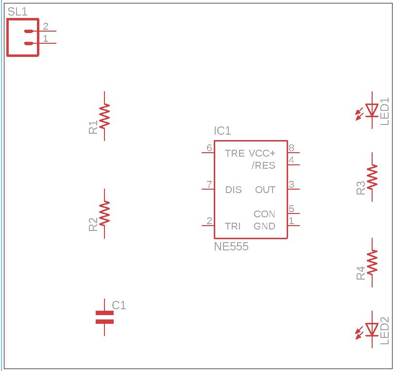
Which does - ???
Anyway - I'll have to return to this on the plane, or maybe Monday. I saw that a few Sparkfun tutorials were added to the class page, so I want to work on those too.