Programming an Output Device
Magic!
Making the Servo Motor
Rob brought us around the lab to look at outputs – motors, solenoids, speakers – and discussed ways each of them can be made and used. He also showed us how to use power sources.
I grabbed a small servo motor, and a stepper motor just in case. The servos look cheap and plastic – I may look for something better for the final project.
My first stop was, of course, the internet – where I found arduino’s Sweep tutorial and a little bit more information about servo motors. I don’t know if the one I have is this one, but this bit of info seems interesting and perhaps relevant: Continuous rotation servos allow the rotation of the shaft to be set to various speeds. Further exploration into the depths of the internet revealed this introduction to servos, which I found very helpful.
Neil’s helloworld board does a neat trick – it controls two motors at once, which I didn’t realize when transferring his schematics. So before I can program my board, I need to decide which of my pins will be the output – and which pins my motor will connect to. For testing, I’ve settled on Pin 6 – I just might find a reason to use Pin 8 in my code.
I asked Rob to double-check my schematic before stuffing the board, because until I know a little better what I’m doing, I can have someone double-check my work. I had the regulator a little bit wrong – the schematic design in Eagle is not very obvious:
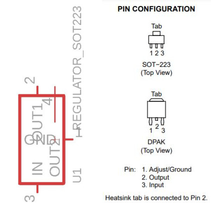
So I got things a little bit backwards, but sorted it out before putting all the parts together – a major improvement over the many times I’ve made a small mistake in past weeks ;)
I have been finding that the boards come quicker and quicker now – both in design and stuffing. This week I made two boards in about an hour – leaving me plenty of time to work on the rest of it.
I also incorporated a 5.5mm power jack, so I could connect the whole thing to an external power source. This too I had some trouble with – another, almost totally incoherent schematic, and a datasheet that’s not in any way clearer. For anyone who’s trying to use the PJ-002AH-SMT-TR in a future class: Contact is ground, Pins 1 and 2 are Voltage, and Shunt is - ???. I actually don’t know. I didn’t connect it to anything, and it all worked anyway, so. It’s fine.

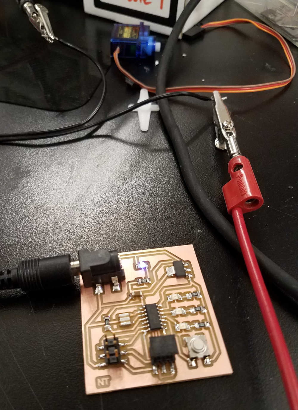
I tested the design using Arduino’s “Sweep” code, just to have somewhere to start. At first, nothing happened – of course, because nothing was plugged in. I didn’t use a serial connection this time, and the programmer cable doesn’t supply power – so the first time I tried to program, it obviously failed. I was a little afraid to have the thing connected to my computer, but when it didn’t short out when plugged into the power source, I figured I could risk it – and whaddya know, it worked like a charm.
Well. Sort of. What you can’t see in that video is that the thing that’s supposed to spin – the white knob on top – isn’t moving at all. I grabbed a different one, which had a little more heft to it, which worked.
Ish.
Now, to Programming. This, I expect, is where I’ll have the biggest challenge, but where I’ll see the most important success. The clock needs to be able to move – it does still show the passage of time. So each hand must smoothly rotate.
I already know I’ll need to make some modifications to the servos (or find another motor solution entirely). However, I would like to see if I can get it to make a smooth transition from one programmed position to the next.
Hum. An attempt at pushing code to the board in my home environment caused the regulators to heat up quite a bit, and in fact in one board even lighting up some of the other LEDs I expected to use only for the purposes of coding. I am not certain what went wrong, however, I have a sneaking suspicion that it has something to do with the house’s old wiring, as this is the only thing that changed between this afternoon, when the motor worked, and this evening. Or maybe – did I test the power cord? Eeee. I think I might have just tested that it lit the LED. Must revisit tomorrow.