<br>
##Analog to digital (ADC) on the AVR tiny45, and use of step response for sensors. Introduction.
Notes and files from an intro session, Wednesday Oct. 31, 2018.
###Analog In on the Arduino.
[program](./AnalogReadSerial.ino)
Here is the basic Analog input program for the Arduino, outputting results to the serial monitor.
The output ranges from 0-1023 as the voltage in ranges from 0 to 5V. The decimal number 1023 is a 10-bit binary number.
Since the AVR microcontrollers operate in 8-bit bytes, more than one byte is needed to use the full scale - actually eight bits
and an extra two bits. This value is accessed as two bytes, a low byte in the register ADCL ranging from 0-255, and a high byte in the register ADCH,
ranging from 0-3. The Arduino libraries take on the job of parsing out the bytes and converting to decimal form to display on the monitor.
---
###Simple AVR c code for analog in.
Use one of the step response boards, the "hello.load.45" board, with analog in on PB4.
[program](./avrc_analog_in/simple_ADC.c)
[makefile](./avrc_analog_in/t45.make).
Access the PB4 pin using a ribbon cable attached to the 4-pin header.
This program sends "framing bytes": "1,2,3,4" so that the parser can determine where the data starts. Then it sends the two data bytes,
first the low byte (bits 0-7), then the high byte (8-9 and eight zeros). We need a way to turn these two bytes into a decimal number.
- Coolterm on Mac and Windows, or term.py cross platform on python, let you look at the output, byte by byte. See the class webpage for this week.
They require that you use an FTDI usb to serial converter in order to get results into your computer.
- One way to get the results into readable form is to convert the ADC result to decimal nubers, and
send the corresponding ASCII characters. I've done that in [this](./avrc_analog_in/simple_ADC_dec_out.c) program.
- The hello-worlds come along with python and javascript programs that parse the results.
These can be used and modified as you need. Still requires an FTDI cable or the [FabFTDI](https://ppatil.pages.cba.mit.edu/FabFTDI/)
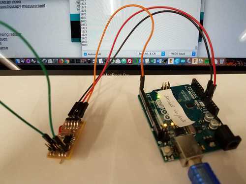
- The Arduino as parser.
[Arduino sketch that receives two bytes and calculates decimal result.](./Serial_in_out.ino)
This is another way that you can examine the data: Use an Arduino board to receive the data
and parse it into a form that you want to see. The Arduino includes a serial to usb converter that lets it talk to the
computer. No FTDI cable needed.
---
###Using the step response rx-tx board.
- Here is an Arduino program that does the same thing as the "hello.txrx" board. It may be clearer for you to see it in this form.
[Arduino sketch for tx_rx](./rx_tx02.ino)
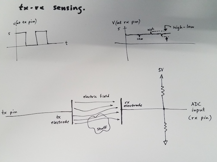
Above is a schematic that describes the function of the tx-rx measurement. The transmit pin is set alternately high and low (5V and 0V).
The receive pin is normally held near 2.5V by the voltage divider formed by the two 1MOhm resistors. When the tx
pin changes, there is a fast transient pulse on the rx plate, either up or down. The microcontroller is programmed to measure
the rx voltage immediately after each tx pin change. The result that we want is obtained by subtracting the lower value
from the higher one. This number increases as the linkage of the two plates by the electric field changes. It is therefore
a function of the distance between the electrodes and of the dielectric material between them.
---
- Programming and using the hello.txrx.45 board. Linked here is [program](./rx-tx/txrx45.01.c) and [makefile](./rx-tx/t45.make) The program is
slightly simplified from the example on the class webpage. Rather than sending the individual values for the up and down
measurement, it calculates the difference high - low and sends it in two bytes (high and low) through the serial pin.
---
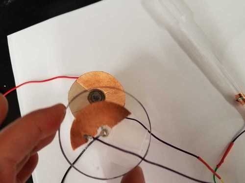
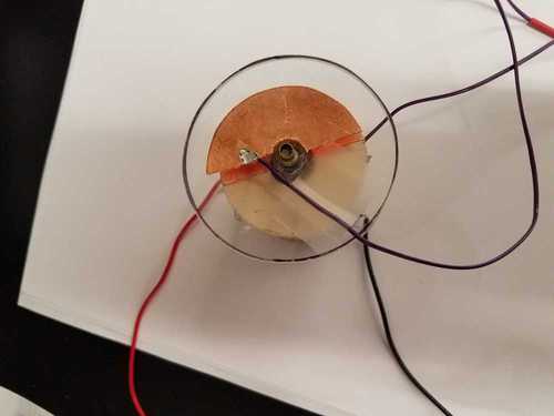
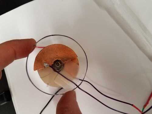
###Several ways to use tx-rx as sensors.
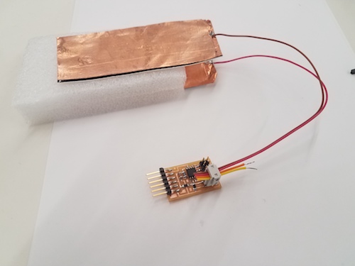
- Proximity between two electrodes lets you measure force through changes in position.
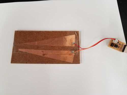
- Wedge geometry as a multi-use sensor.
- Tilt sensor. Bottle partially filed with water.

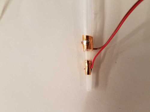
- Pipetter liquid sensor.
- A crude rotary sensor.