<br>
##The simple board.
We will provide several programmed copies of this board, some functioning, and some broken. This board is simplified relative to other
"hello world" examples, because it lacks the ISP programming pins. It can be programmed before soldering (by contacting pads on a standard ISP board) or
after soldering in place by using the
["pogo-pin" programming header](http://fab.cba.mit.edu/classes/863.16/doc/projects/Pogo_prog_connector/Pogo.html).
We will use the [FabFTDI](https://ppatil.pages.cba.mit.edu/FabFTDI/) for serial communication and to power through the "FTDI" header.
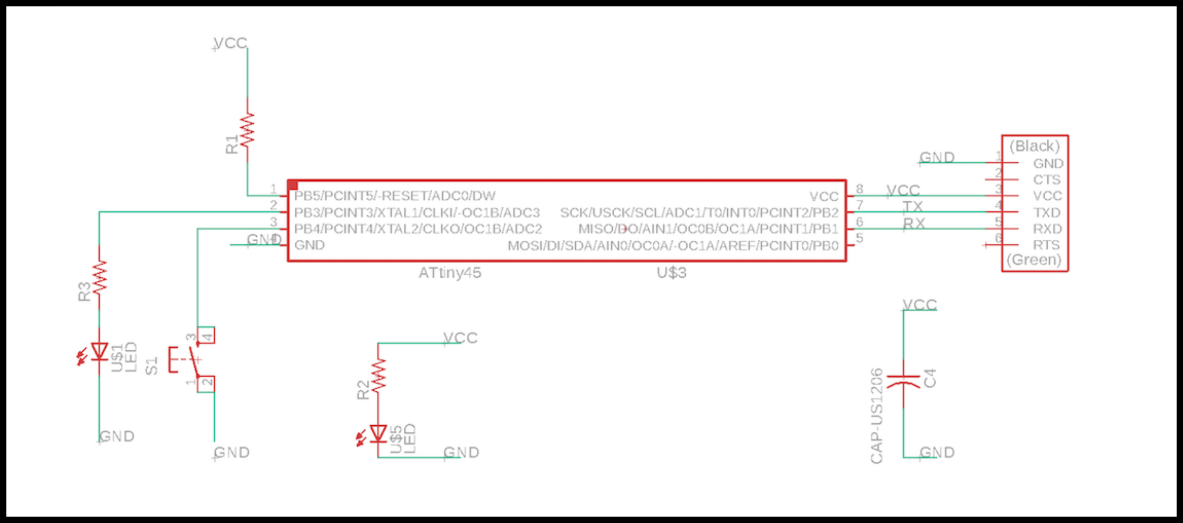
- ###Eagle Schematic is shown below.
[Eagle schematic file](./test_simplified.sch)
---
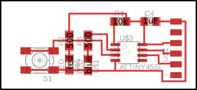
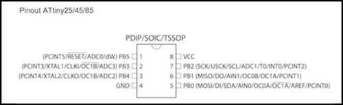
- ###Eagle board on the left. &nbsp; &nbsp;&nbsp; &nbsp; ATtiny45 pinout on the right.
[Eagle board file](./test_simplified.brd)
[traces](test_simplified_traces.png)
[outline](test_simplified_outline.png)
[ATtiny45 datasheet](http://ww1.microchip.com/downloads/en/DeviceDoc/Atmel-2586-AVR-8-bit-Microcontroller-ATtiny25-ATtiny45-ATtiny85_Datasheet.pdf)
---
- ###The board and the microcontroller program:
- The [program](./test_board.c) and the [makefile](./t45.make).
- The board is powered through the "FTDI" header on the right side. Pin 1 is ground, pin 3 is power (5V). Pin 4 is connected to a microcontroller pin (PB2).
Pin 5 is for sending data (from microcontroller pin PB2).
- One LED (red) is wired to be always on when power is applied to the board.
- A button is attached to PB4. PB4 is set as an input with
["<u>input pullup</u>"](https://tourlomousis.pages.cba.mit.edu/fabclass-recitation-electronics/microcontroller/index.html)
activated. (see programming week for details.)
- When the button is pushed, the second LED (blue) toggles on and off. LED is driven by a 50% PWM waveform from PB3.
- Every 50 mS, one byte, corresponding to the ASCII character "M", is sent from pin 6 (PB1) at 9600 baud (bits per second). Each time a byte is
sent, the pin PB2 (physically pin 7) is toggled between 5V and 0V, just to give us another signal on a pin that is otherwise not used.
- [ASCII](https://en.wikipedia.org/wiki/ASCII) "M" is coded by the decimal number 77.
- Decimal 77 = 4x16 + 13 = Hexadecimal 4D = binary 0100 1101.
- 9600 bits per second corresponds to 104 microseconds per bit.
[Information on RS232 serial protocol.](https://wcscnet.com/tutorials/introduction-to-rs232-serial-communication/)


##Things to measure.
- ###Digital Multimeter (DMM)
- With the board not connected to power, check continuity of traces and solder joints, using the DMM audible setting in resistance mode.
- Still in resistance mode, measure a resistor value.
- Use the DMM to check for correct orientation of the LEDs.
- Plug the board in to a power supply using the "FTDI" header. Set the multimeter on DC voltage mode, using proper scale.
- Connect the ground lead to the board ground, using a clip lead. [Picture](./ground_dmm.jpg)
- Check VCC.
- Check pullup resistor on reset pin.
- Measure voltages in the "always-on" LED circuit.
- What is the voltage drop across the resistor? (Two ways to get this.)
- The resistor is 500 Ohms. Calculate the LED current.
- Measure the voltage at pin PB4 with button not-pressed and pressed.
- Measure the voltage at pin PB3 (LED pin) when LED is on and when it is off. What's going on?
- ###Oscilloscope.
- [Scope picture.](./scope.jpg) &nbsp; [Probe picture.](./probe_pic.png)
- Connect the ground lead to the board ground. [Picture](./ground_scope.jpg)
- Using the Auto-trigger mode, look at VCC and other voltage levels on the board.
- (optional) Unsolder the filter capacitor and see the difference in the 5V waveform.
- Attach the scope probe to the 4th pin of the FTDI header (connected to PB2), to observe the toggling of that signal every 50 mS. [Picture](./signal_pin4.jpg)
- Push the button to turn the blue LED on.
- Use the scope probe to observe the PWM waveform at pin PB3 (physically the second pin) of the t45.
- Set the triggering mode and the time base to get a stable display.
- What are the voltages?
- How long is the waveform "off" and how long "on"?
- What is the PWM frequency?
- Is the LED flashing on and off? Why does it look continuous?
- Using the same triggering method, capture the (serial) waveform being sent from the microcontroller at pin PB1 (5th pin of the FTDI header).
- What is the duration of one bit?
- What does the pattern of high and low voltage mean? You should be able to see:
- a start bit.
- eight bits of data
- a stop bit.
---