

This page will be organized by section of the pinball machine. Within each section will be a material list, how to build this section and any pitfalls I had in between.
Background - What has been done before and what does it do?
Pinball machines have been around since the early 1900's. The concept over the past century has remained the same
a metal ball is ejected onto a playfield where the ball can bounce off of other objects and enter certain areas
to gain the player points. The goal of the game is to garner as many points as possible without letting the ball
roll past the flippers will the game will end. The flippers are there such that the player may intervene to get
the ball into certain section and prevent the ball from rolling into the end game section. The game is typically
fast paced, has a lot of lights and sounds and an incredible amount of moving parts. As such there has been a ton already
done in the world of pinball from the electrification of its parts, to adding digital displays to a whole movement of people
who make pinball machines at home.
I am not adding any particular new facet to the world of pinball. I am aiming to build as a robust of a pinball machine as possible
while ordering as little parts as possible within the time I have. Below details how I (almost) made a pinball machine.
Pinball Cabinet
Material List and Machines Used
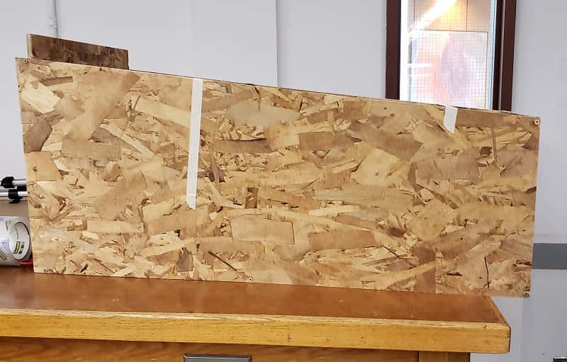
2 1/2" 4' by 4' OSB planks - Home Depot - $18
Shopbot - Provided
12 1/8" by 1" screws
Screwdriver - Provided
CAD, Shopbot Files and Construction
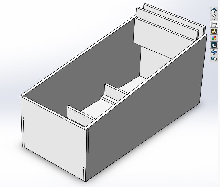
I created a pinball cabinet as shown in the images below. My pinball cabinet consist of a rectangular box, and interior planks to provide the necessary slope for a pinball machine. I found a lot of resources and help in the creation of my pinball machine, both the cabinet section and non-cabinet section alike, from this wordpress website and Space Eight.
The CAD for the pinball cabinet was shared by Space Eight. However, I modified the design to remove several pieces such as the backstop
the original CAD files can be found here.
The crv files can be found here:
first hall of the cabinet
second half of the cabinet
For the details of the modification, you can find them in the shopbot files found here:
first hall of the cabinet
second half of the cabinet
This is where one of my pitfalls for the creation of the cabinet came in. I didn't flip one of the side pieces
to ensure that the orientation of both sides pieces would leave the smoother finish of the OSB exposed. You should be sure to make that change
if you replicate this process.
After importing the bodies of the pinball cabinet and creating the shopbot file,
I then created the drillpaths. The files for these paths can be found here:
first half
second half
The pinball cabinet itself get constructed very similar to how you see in the photos. The two trapezooidal pieces are the side of the walls. The long rectangle is the bottom, the short rectangle is the back and the square if the front of the pinball cabinet. One note about the back wall. This piece should sit a little further in along the trapezoidal walls. When screwing in the pieces, be sure to maintain right angle and be careful of the wood splintering. You want to use screws in case you need to take the cabinet apart but you should avoid doing so as much as possible as to not cause more splintering. The support inside of the cabinet should go tallest in the back to shortest in the front to allow for sloping.
Flippers
Materials
Shopbot
4" by 4" Block of Wax
Oomoo
Tin
Oven
How to Make the Flippers
I started by creating this CAD of the flippers found here
This flipper has the geometries of the standard pinball flipper, including the connecting point for connecting to the solenoids.
However, since I am molding and casting my flipper parts and did not want to do more than a two part mold
I lose the insertion point of the solenoid connection and some of the geometries.

first half of the flipper
second half of the flipper
From there you want to create you shopbot file to carve the mold into your wax. My shopbot files can be found here:
first half of the flipper
second half of the flipper
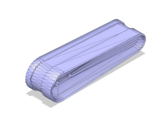
Once you have your wax you should have a mold that resembles this:
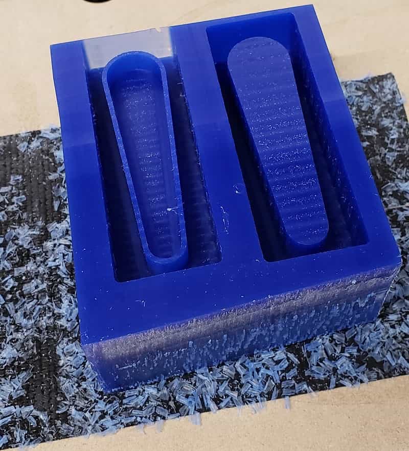
The next thing you want to do is to fill that mold with Oomoo. This will create a silicone rubber mold for you to cast you flippers in any other material you want. This oomoo will take roughly 3 hours to set. Once set, you need to puncture 2 holes into the mold, one for air flow and one to pour in you matierals. I recommend making the hold for the material slightly smaller than a dime. I would recommend putting the material pouring hole on the larger side of the mold and the air hole on the other half. From there, you will want to melt your tin. Place the tin in an oven at 450 degrees F for 20 minutes. During this time, coat your mold in talcum powder. Clamps your 2 part mold shut assuring they aligned. I found the best way for me was to have two pop-sicles sticks on either side and then using c-clamps on the popsicle sticks for pressure and support. Once the tin is melted, quicky pour in your metal and let the mold cool. You should then have working flippers.
Flipper Attachement
Once I casted my metal flippers, I then work to find a good mounting, spring with enough tension and a set up to
actuate the flippers for the players. Initially, I planned to have 2 arcade buttons triggering a solenoids to push against
the flippers. However, I found a ton of difficulty in this section.
1) I couldn't find a spring with enough tension
or figure out a way to have it automatically reset.
2) I didn't have enough solenoids with a high enough voltage (24 V solenoids) to give enough movement of the flippers.
3) I didn't have enough time to build 24 V solenoids
4) I had difficulties finding ways to mount any of the materials within the pinball cabinet and on the playfield.
Despite my many of difficulties, I was able to work with Joe to create a reasonable method for the flipper. We decided
to appropriate the structure of a mousetrap to provide the spring tension and reset methodology for this. We cut away
half of the wood backing of the mousetrap to only leave the swinging metal exposed. This gave us clearence for our
metal rod to pivot. The initial plan was to still
use a solenoid and a metal rod to push against the mousetrap. We intended to use this metal rod like a lever.
The solenoid would push on the shorter side to create a larger displacement with
the flippers. The connection would be made by drlling holes into the metal rod and ziptying it to the mousetrap.
However, I found the connection from the metal rod to the mousetrap to be unstable.
After the failed attachment, I instead bent aluminum to crate metallic handles. I drilled holes into the handles and attached them via zipties
to the mousetrap. I also drilled holes in the base of the handles and attached them to the mousetrap with zipties. I found
this attachment to be more study but I think that is because I attached them in a perpendicular manner from the earlier version.
The mechanical method allows for the user to get a high amount of force into the flipper. The mousetrap set up themselves
was attached to the first supporting/sloping plank in the cabinet. I just screwed it in.
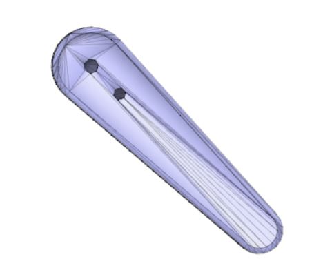
I worked to attached the actual metal tin flippers by drilling to holes into it. One for a stable axis and the other to connect to the mousetrap to all the part to spin. However, I couldn't find the right washer/bolts to allow this to happen. As such, I didn't connect the physical metal flipprs to my project.
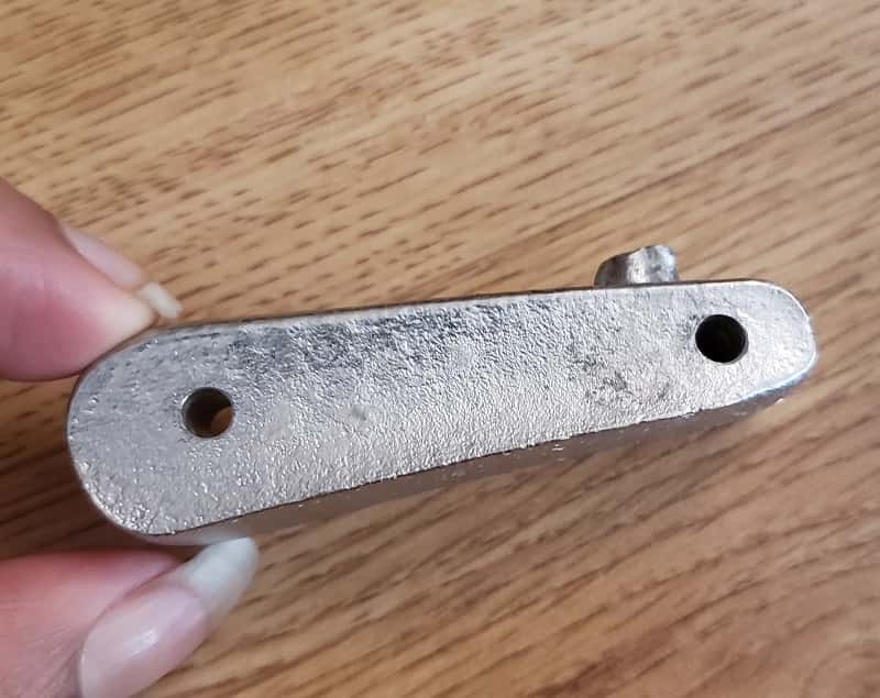
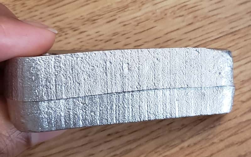
Below are images of well cast flippers:
Playfield
Due to time contraints, I never actually got to make the playfield. I made the playfield shlef out of cardboard and cut it to 39 by 89 cm such that it can comfortably fit in the pinball cabinet.
Seven-Segment Display
Materials
5 Single Side Copper Clad
35 White LEDs
5 AT Tiny 44
5 2x3 Headers
5 6 Pin FTDI Pins
1 10 K Resistor
1 Microfacrad Capacitor
35 500 Ohm Resistors
Deisgn
This board is designed such that I can lgiht individual LEDs to create the sturcture of a specific number. As such, I put seven LEDs on an individual pin and shaped it such that it looks like a seven segment display. You can see the outline of the overall numbers in the photo below:
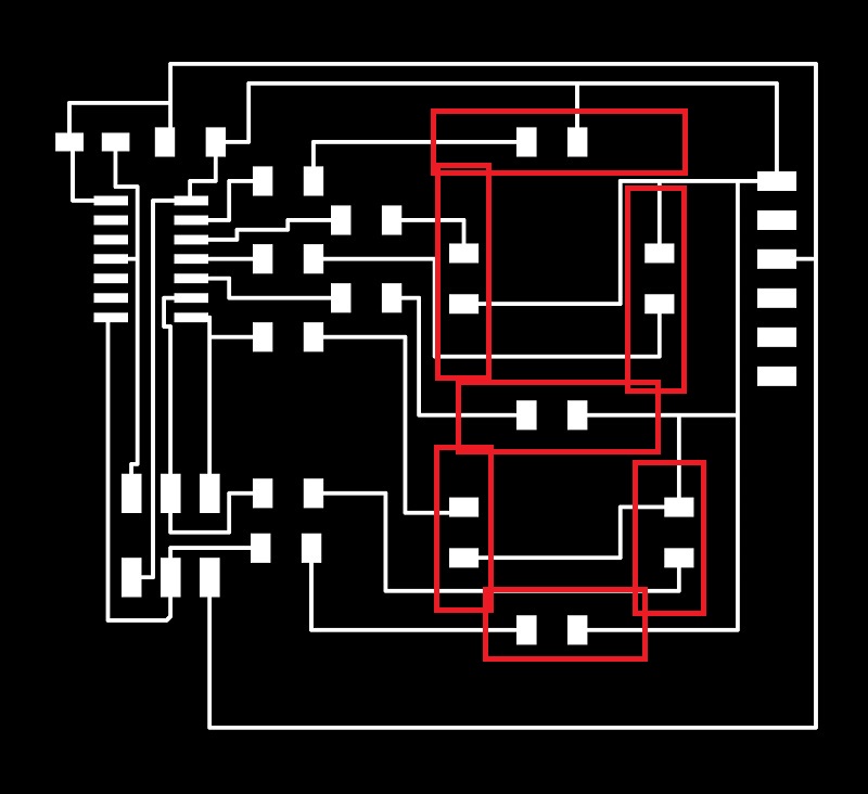
I have also detailed the what components go where on the image below.
1) White LED
2) 500 Ohm Resistor
3) FTDI Header
4) 1 micro capacitor
5) 10 K resistor
6) 2 x 3 header
7) AT Tiny 44
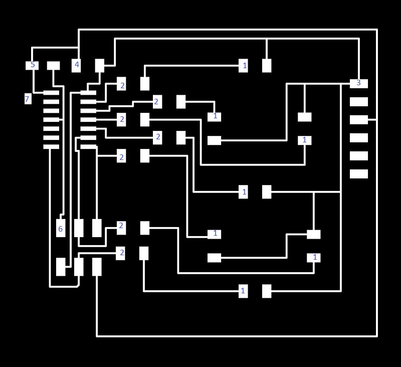
Deciding the where to place the traces wasn't difficult but I did create a couple of errors for the milling process. For pin 5 of the AT Tiny, the trace just inside of the of the pin is too close to the pad. You will need to scrape that section a bit post milling. Also, all my traces were too close for the tolerance of the machine. I had to set the diameter of the tool to be smaller than what i actually is. I set the tool diameter to be 0.0133. This also create really thin traces. However, the overall board worked really well.
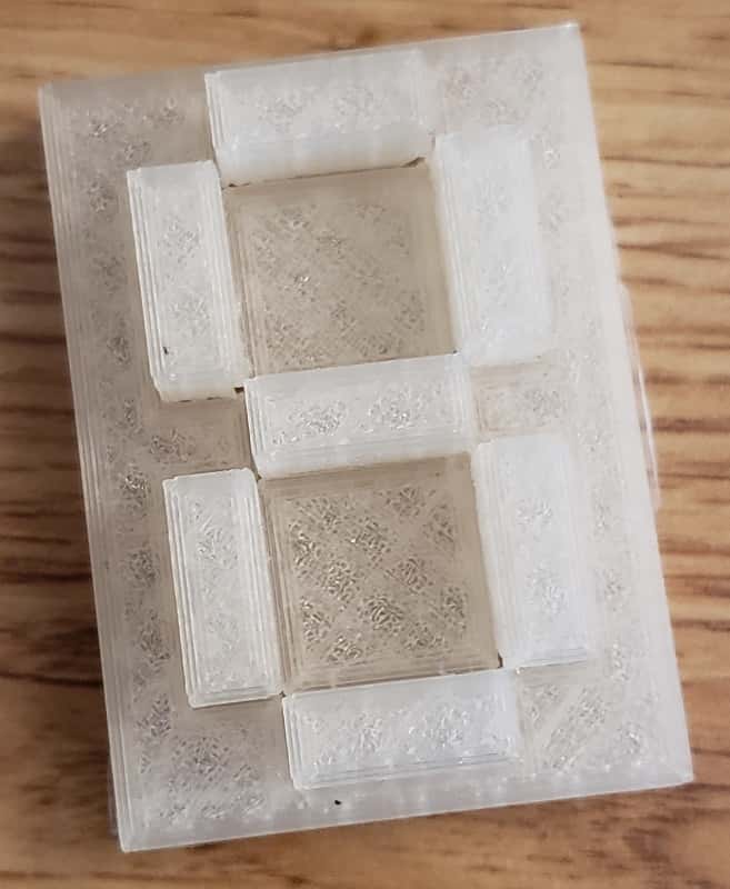
3D Printed Case
Because the seven segment display is built off of 1 LED per pin. I decided to 3D print a case that would better project the images of the
numbers for users.
My first attempt, I made the base way to thick to really work for the situation I am going for. That document can be found
here.
However, I reworked the file to have a much more proportionate case which can be found here.
The overall problem lied in the fact that we didn't have a clear enough PLA to print with within the lab so the printed objects didn't
provide more clarity. For that reason, I did not physically attach these cases but brought one of them with me physically.
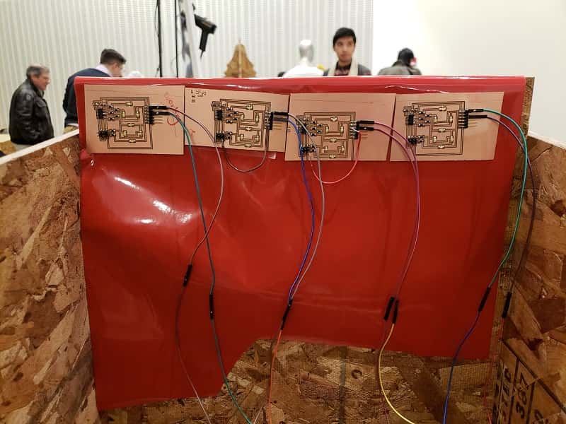
Networking Attempt
My original intent for these seven segment displays were to have them operate as the scoreboard. However, I never got to build a playfield
so I omitted the scoreboard method from the overall pinball machine. I would still like to include that process in this documentation because I got
it working. I just had no way of tracking a score without a playfield.
For this method, I connected the arduino's tx and rx lines to pin 5 and 6 on all of my AT Tiny's to create a serial bus.
The arduino set out the score as a string and the board would index into the score to find their appropriate digit and then
display it. The code for this can be found here.
Timer
Because I don't have a playfield to generate a score I built a timer under the idea of showing how long the game be played. At such I repurposed the scoreboard to become a timer and the code can be found here. The delay changed with every ones place to ensure that the scoreboard counts correctly.
Breakbeam Sensor
Materials
IR LED
IR collector
1 K resistor
10 K resistor
Schematic
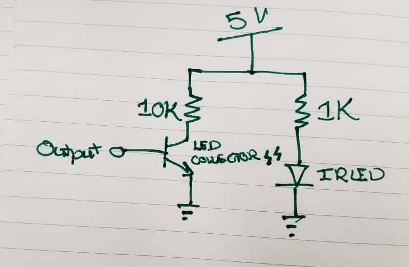
Code
I built this sensor directly into an arduino with the IR collector functioning as an input and IR LED as an output. The last step was to code the sensor as seen through the code below. I programmed it to read in the analog signal from the collector and found that when there is no IR light reaching the collector the analog signal will read >1000. The most direct connection between the collector and the emitter will read around 20-30 for its analog signal. When this sensor is placed within the playfield of my pinball machine, I will set the code to set of a series of lights denoting game over any time the analog signal is greater than 1000. The code for the breakbeam sensor can be found here.
Arcade Button
I utilized an arcade button as the reset/begin game swtich for my pinball machine. This button has two connection points, the LED and button components. I connected the LED as an output to the arduino and the button aspect as an input. The LED and button are always set with power as soon as the arduino is power up. The arduino listen for the button to be pushed and if it is, then it powers the rest of the compenents of the board. More information about the code of this section can be found in the integration section. However, you can see the use of the button in the video at the top of this page and at the bottom.
Integration
The last step of this project was to incorporate these 3 larger parts and attempt to incoporate the flippers into the board.
I unfortuantely, never got to fully incoporate the flippers because I struggled to figure out the mechanics of having them
sit within my pinball machine.
However, I did get the scoreboard, the breakbeam sensor and the arcade button fully integrated with each other. To begin, I will
start with the breakout board which connected all of my scoreboards to the arduino.
Breakout Board
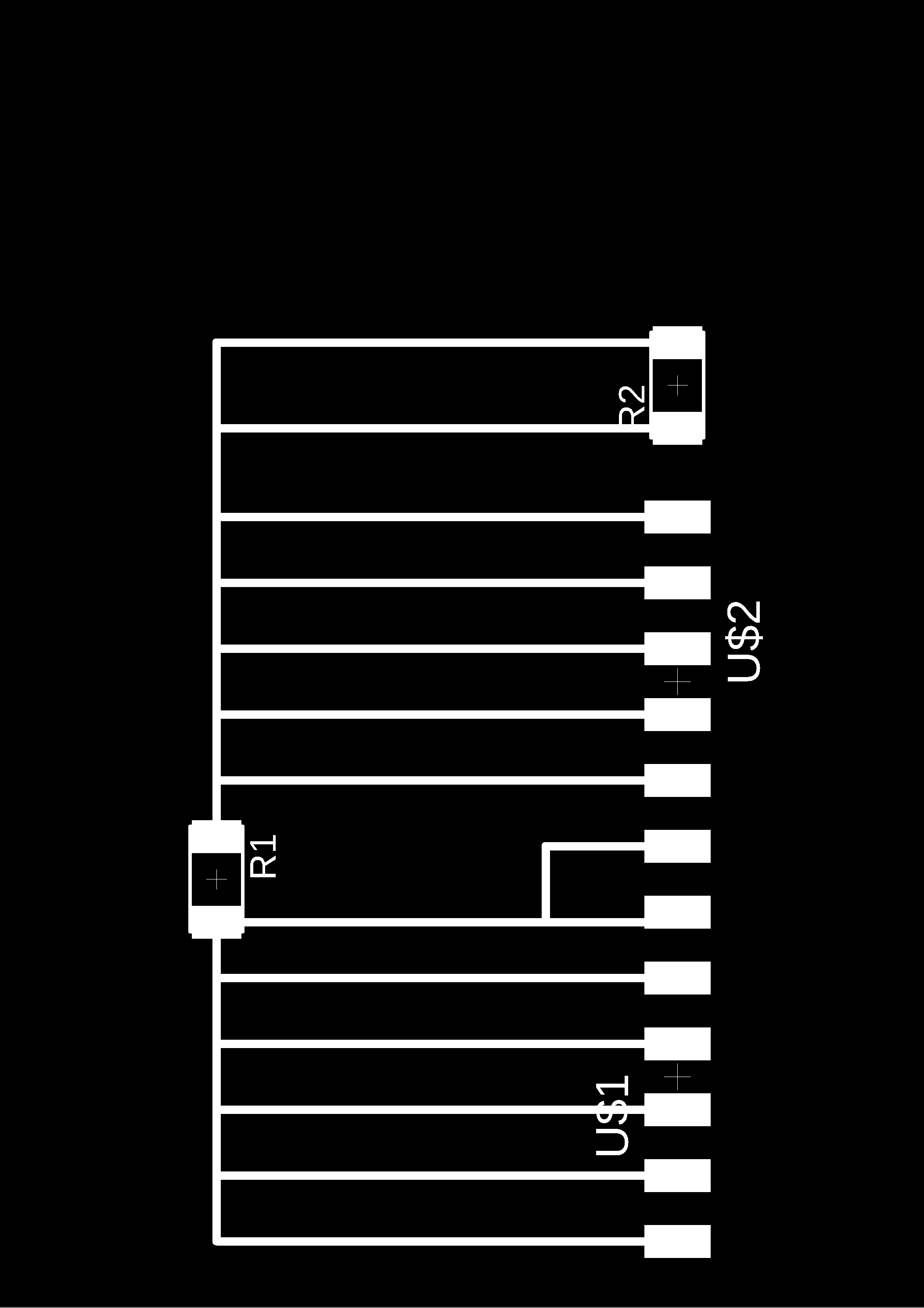
The breakoutboard consisted of 2 7 pin FTDI headers, and 2 2 pin FTDI headers. This created the serial bus line for my scoreboard and the arduino connecting TX and RX. In addition, this powers the scoreboards themselves. Below is an image of the board traces.
Arduino Code
The arduino code is where most of the integration happened. Here is programmed for the
button to be the only thing powered in the beginning and then the change in state of button enters
the pinball machine into it's fist condition.
In this state, the scoreboard automatically begins counting and the breakbeam sensor is activated.
This would be the start of game play and if I got futher would have also drove power to the
playfield, LEDs and sound components as planned. While the scoreboard counts, the sensor checks
to ensure that analog signal never goes above 1000. If the sensor does, the arduino kills power to the scoreboard,
breakbeam (and theoretaically the playfield) to ensure that game is over.
The code for this section can be found here.
