This week we worked to replicate Brian's in-circuit programmer by PCB milling and soldering a board. While I have never milled a board before, I had familiarity with soldering and creating circuits as my background is in electrical engineering. With that being said, my board and my experience through this week wasn't perfect.
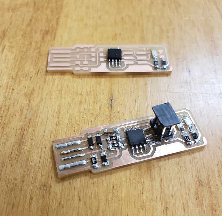
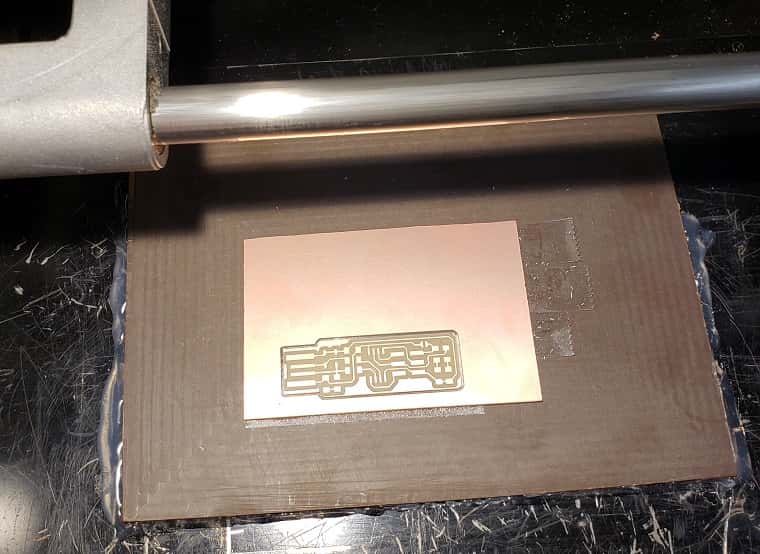
This week I actually milled two boards. The first board went suprisingly well in that I cut a really nice board with my try. As shown through the first photo below. I started soldering that board but realized I should probably get practice creating a second board. This is where things didn't go perfectly. My first attempt of my second breadboard, I didn't ensure the double-sided tape along the back holding the board to the mill didn't overlap and thus had a bit of an uneven board and the 1/32" tool lifted upand couldn't actually cut into the board. I corrected the two issues and then created the board I finished all my soldering on.
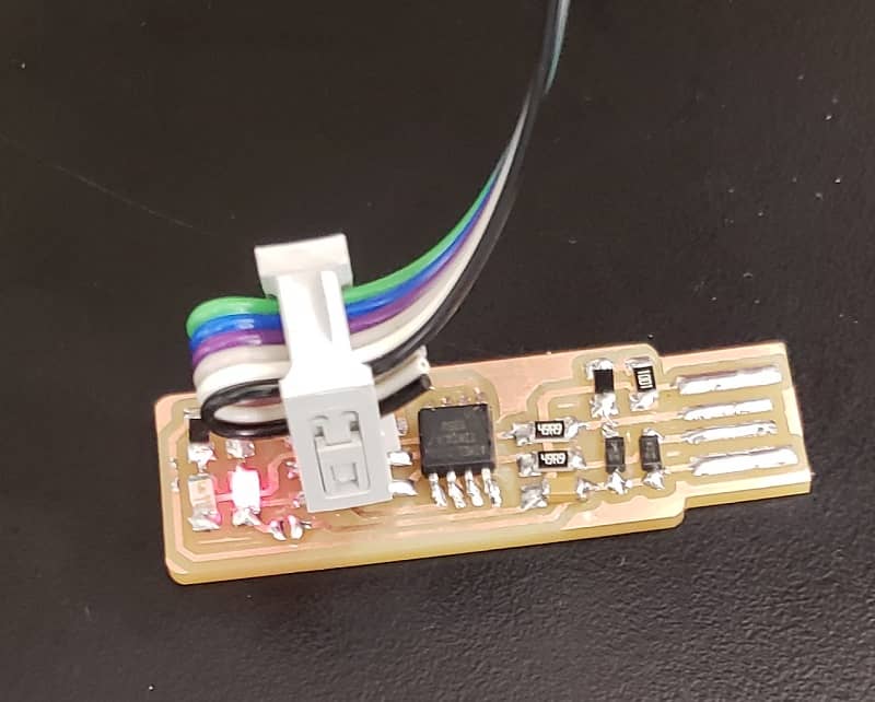
I continued to follow Brian's steps to solder the components onto the board. While all the solderign joints are shiny, many of my components are a bit crooked. I particularly found soldering down resistors and capacitors diffuclt as my force on them when soldering would cause them to jump when I tried to solder down the first side. This caused my components on by breadboard to be a little crooked. However, all the components on my by board worked as evidenced by the photo below.
For the exact details of how this board was created please refernce this page.