

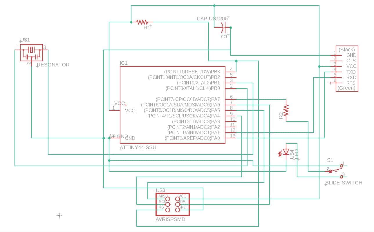
This week we were asked to recreate the Echo Hello World board by redesigning the circuit, adding a button and an LED, mill, solder and test the board. This week, I have also been met with difficulties every step of the way. I have had previous experience in creating in digitally desgining boards but in different programs than the one we used today. This just created a lot of frustration as I attempted to build the schematic and board. Functions and inputs that felt familiar wouldn't work and I couldn't figure out how to create the changes. Despite, my difficulty switching to Eagle, I was able to create the schematic and the board. However, I didn't appropriately use the name function for creating the schematic which made it hard to read.
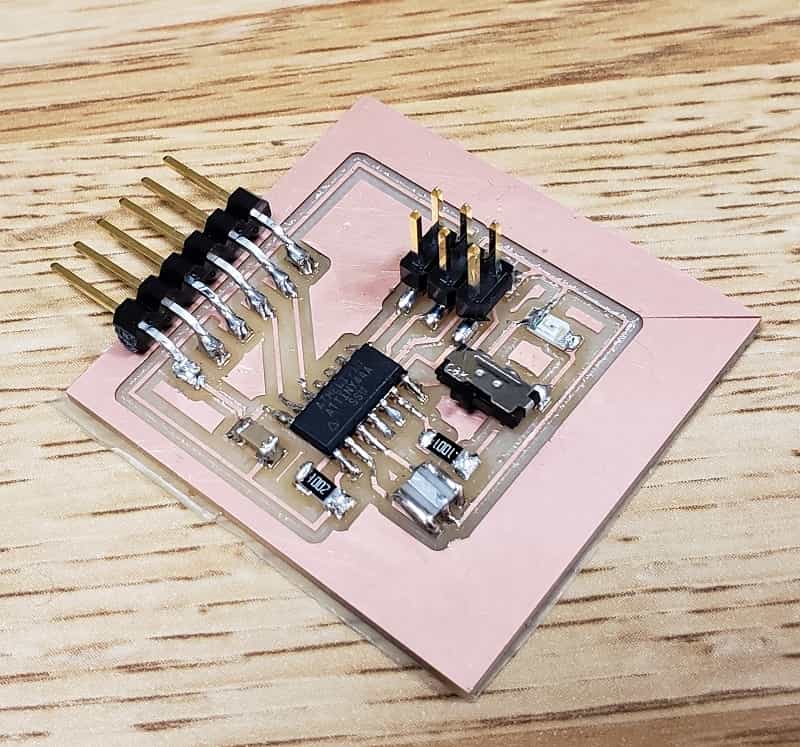
The next difficulty I ran into was milling the board. The first time around, I didn't export my trace with a high enough DPI which created a board that looked like a toddler drew it and my routes were too close together that the connection was missing at particular points. After correcting my DPI mistake, I created the beautiful bread board above. I then soldered all my components but I changed the button and LED inputs from the anticipated one. Instead, I am creating a double-trigger switch to the LED. The soldering process went smoothly! I tested and all of parts have the correct voltage and connections as checked with the voltmeter. However, my board cannot be programmed. I went through my board with Rob to double check all my connections; we couldn't find the mistake so I will have to recreate this breadboard.
For this week's files, you can find them here:
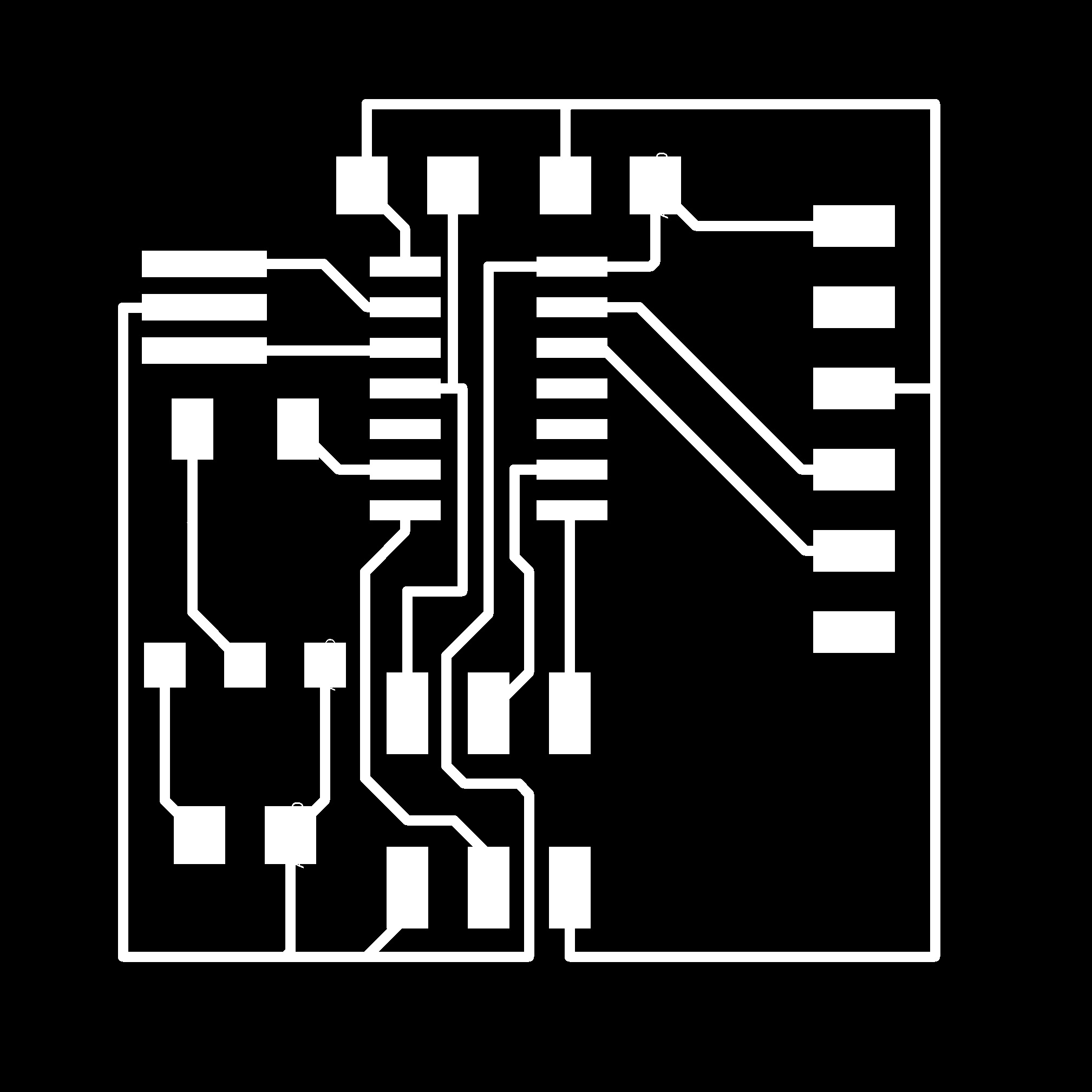
the traces
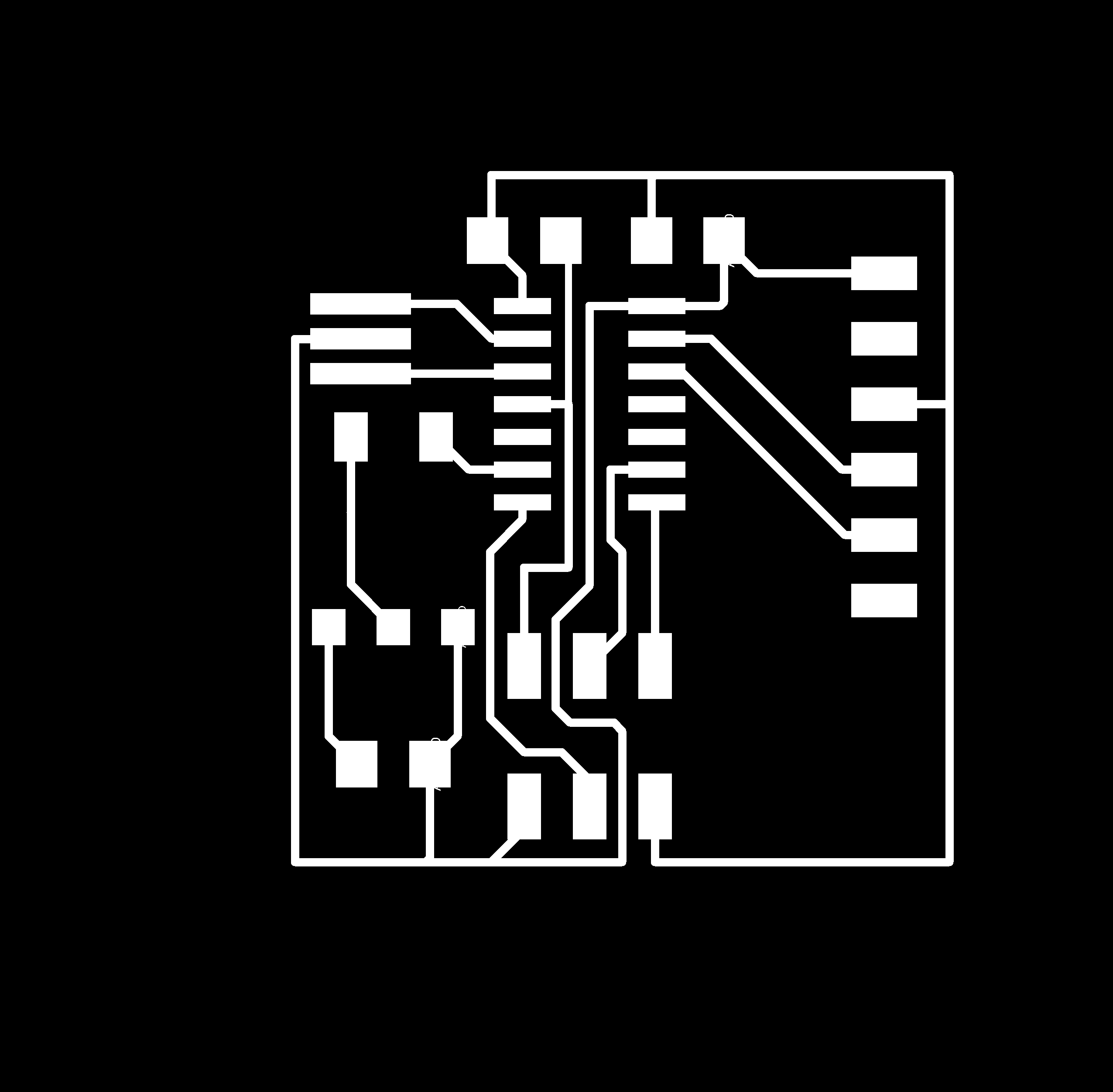
the outline of the board