how to make (almost) anything
Architecture Shop: Machine Week 2019
Wednesday, Nov 20th
At the conclusion of class, we met quickly as a group with Molly and Jung, and scheduled our first project meeting for the following morning. In preparation for that discussion, we set up a google doc to brainstorm possiblities for what the Architecture machine might do.
Group brainstorm of possible machines
Thursday, Nov 21st
Full Team Meeting
There were great concepts brought to the table! After some discussion, we decided as a group to move forward with Morgan's idea for a Claw Machine, and drew through basic relationships to consider. A thread of our conversation centered around what the claw should pick up--we settled on a game (of sorts) where you would use the claw to move and pop balloons.
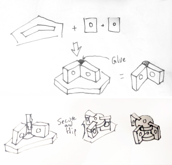
Our strategy for breaking apart and organizing our efforts for the week was to think of the machine as a series of modules that would be both designed and fabricated within smaller teams. These teams would stay in close communication to keep the larger group aprised of progress and questions, and coordinate closely with the other module teams with which their portion of the machine directly interfaced, so that important relationships and decisions throughout the design would align. Everyone volunteered for the module(s) they were most interested in being a part of, and we assigned teams (see left).
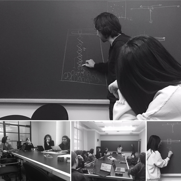
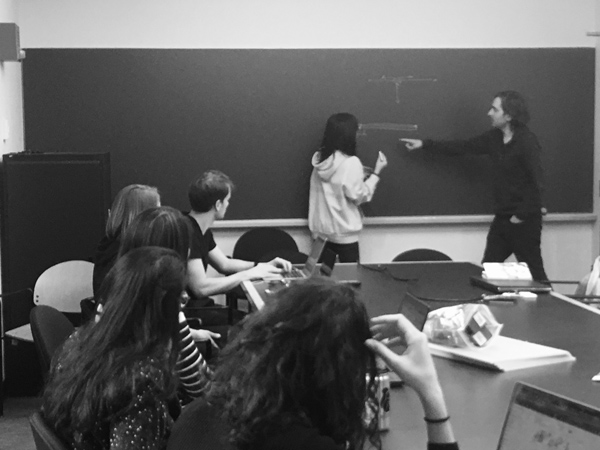
Working through ideas during the team meeting
Friday, Nov 22nd
Claw
Claw team designed the carriage and spool for z-axis movement, which was 3D printed overnight. We also designed an oversized claw prototype that will be laser cut from cardboard.
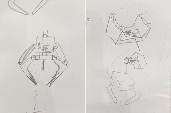 Claw sketches--watch out for that needle!
Horizontal Axis
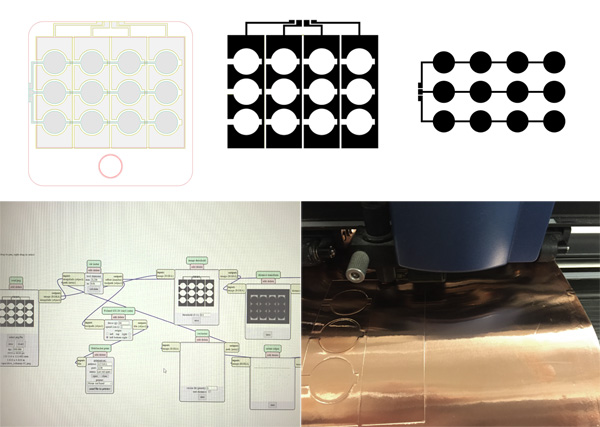
Friday evening the team met to start laser cutting and 3D printing the necessary pieces. We did some test pieces on the acrylic that would require 3 passes at a 12/70/5000 setting to get a clean cut with good tolerances on the laser cutter. However, the laser cutter was a much more arduous process and required several more passes due to the quality of the machine being used and the nature of the material -- the machine's mirror laser focus needed to be replaced and the material was bending upward. These problems could have attributed to problems with the tolerances, but fortunately, in the future these problems did not come up. We also started some 3D prints for carriage pieces in the architecture shop Sindohs that would take 15 hours plus for overnight. A teammate had access to the IDC so the 3D printed joints were sent there. We made sure the printers were started and then decided to come back and check on it in the morning.
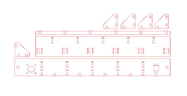 Laser cut files ready for fabrication
 Horizontal axis assembly
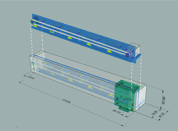
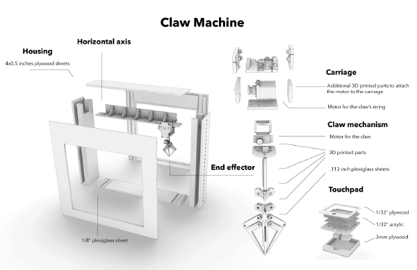
Housing & Design
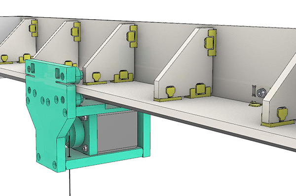
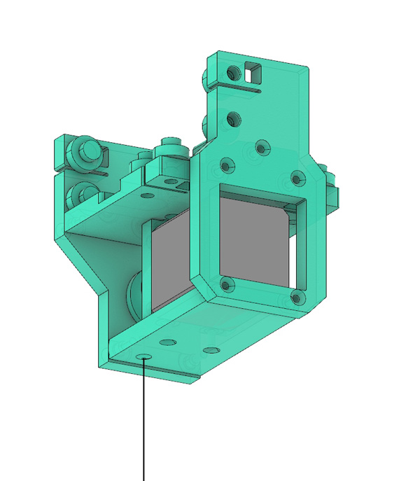
Friday was dedicated to designing the house for the machine. At our group meeting on Thursday morning, we decided we would only use one axis. This decision came. after we decided we were going to make a claw machine. Only using one axis, the box from which we would claw would have to be quite thin. As a result, we thought it would be cool to make something similar to an ant farm: a thin box with a very minimal frame that would hide the moving carriage and the wiring. On Friday morning, we met to design the machine housing. The axis team sent us a screen shot of what they were working with and after speaking w Molly, we agreed it would be good to ask the axis team to flip the carriage so that it would be facing down vs to the side. This would allow us to have a thinner box. We made a very simple box but we couldn't keep working without knowing the dimensions of the axis. Elina and I met later Friday to discuss and we agreed to add length to the axis and this length would allow space for the axis to sit on the housing safely.
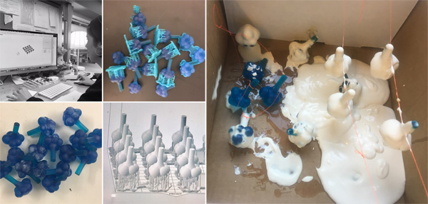
We felt the box would be pretty straightforward and we wondered if there might be any way to design out own balloons. We looked at a couple of videos on balloon manufacturing and discovered, we could maybeeeee do so. So, we designed a cloud-like balloon mold to 3d print and we purchased eco-flex on amazon prime after we saw a student who had made an inflatable project on the HTM website. We will try to dip these in the eco flex and hopefully blow up some funky looking balloons. If this fails miserable, which I'm almost sure it will, we will go ahead and purchase regular balloons! No harm no foul!.
 Development of machine's housing & channels to conceal wiring
 Cloud molds for balloon fabrication
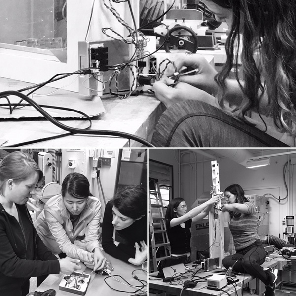
Electronics & Coordination
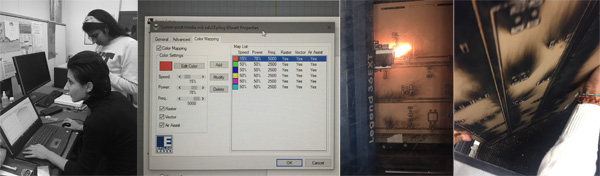
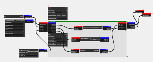
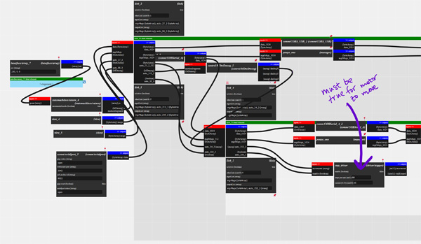
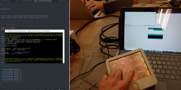
Electronics team met Friday morning to plan the strategy for the electronic systems for the machine. We hooked up the motors to the control boards and tried to start talking to Cuttlefish, but it was clear that we would need to meet with Jake to get everything talking together. We decided to control the machine with a capacitive touchpad and looked for previous examples.
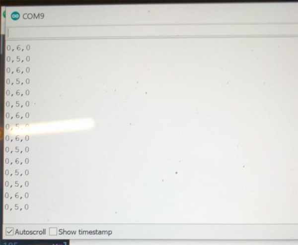
We loaded Jake’s example from recitation. We were not able to get the nested box within the router window (the window representing the motor board) to refresh. This means that we were not able to connect to this board. We remade our ethernet cable in hopes that it was a cable issue but this didn’t work. Jake came to the rescue and helped up troubleshoot in the arch lab. We made our own program in cuttlefish that talked to the serial port A of the motor board. When this didn’t work we tried port B, then port C.
Next we went to the oscilloscope and used the program below to attempt to send data from the router board through port B. We observed the LEDs on the router board saying that signals were being sent. However, oscilloscope-ing the outputs of the serial port showed that those signals were not actually being sent:Somehow the signals from the chip were not making it to the serial port. Th board was trying to send serial data, but the scope reading showed no signals. Jake luckily had 1 extra board. We connected it to the motor modules and were able to connect.
Saturday, Nov 23rd
Claw
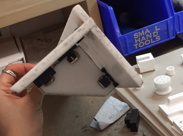
Redesigned and reprinted carriage to accommodate electronics. Designed servo board to control servo via button. Designed claw actuation mechanism (string, arm, and pulley system). Redesigned claw pieces to fit inside the design of the housing.
 Claw carriage on horizontal axis
 Claw prototype
 Board schematic to run claw motor
Horizontal Axis
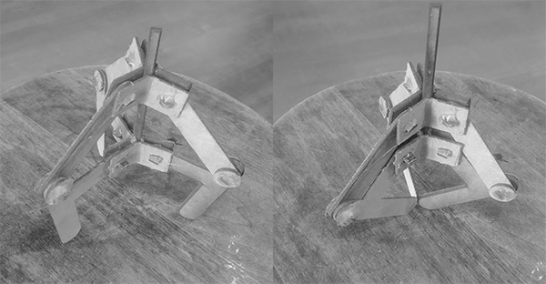
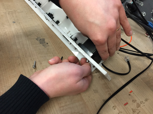
The 3D printed joints from the IDC succeeded, while the Sindoh 3D prints from yesterday horribly failed (see pics), so we decided to try again, but this time, we would just do one piece at a time instead of 2-3. Each print on the Sindohs were still estimated to take 6-12 hours. We set them to print in the morning and would check on them throughout the day. We finished laser cutting the acrylic and then had to sand it down and clean it with alcohol. By this time, we went to go check on the Sindoh prints, and one failed, while the other one was continuing to struggle along (it would fail later, no worries). We decided to try to get access to the IDC to go pick up the joints that were printed the day before and try to put some more prints. We got access and set the new prints (with great success and would only take 3 hours compared to the 12 hours on the Sindoh). Back at the archshop, we began assembling the horizontal axis -- heat sinking some of the brass screws and screwing in the larger acrylic pieces.
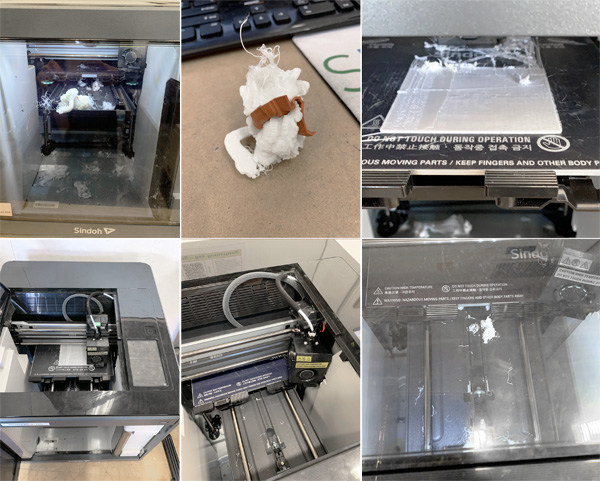 Failed prints
 Axis being assembled
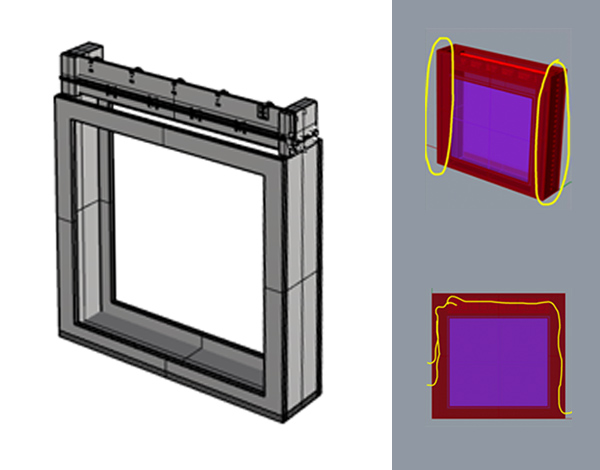
Housing & Design
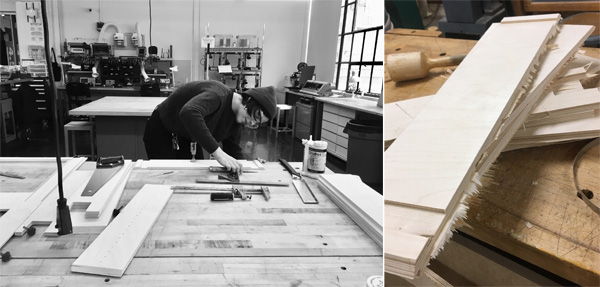
The machine housing ended up being pretty substantial, Marianna had some leftover plywood, but not enough for all of it. Chris told us he had a 5'x5' piece of stock, so we decided to take that. A 4x4 piece of stock if $55 so we assumed it wouldn't be much more than that and with our group being 16 people, each person would pay probably no more than $5. The edges are mitered, and the main face of the machine has a lip that makes assembly easier. If needed, we can reinforce the box w nail, but my OSB box is holding up pretty good as a result of glue and clamps! we also sent the balloons molds for printing in the formlab, it will take around 30 hours of printing.
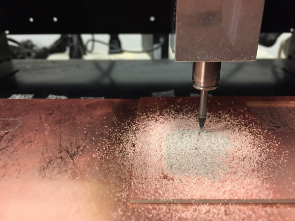
 Housing cut files for CNC
Electronics & Coordination
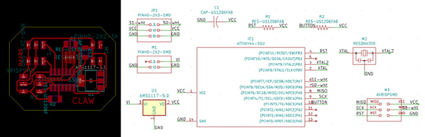
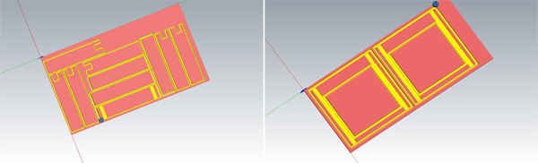
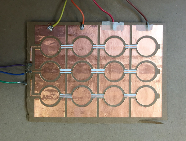
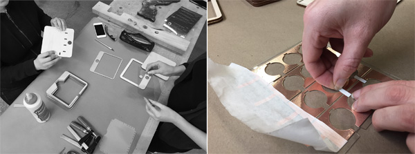
We modified and designed the PCB boards to control the motors with the capacitive touchpad. After milling the board, we added the components. We designed the capacitive touchpad and used the vinyl cutter to produce a prototype.
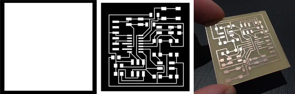 Capacitive touch board
 Touchpad design and vinyl cutting
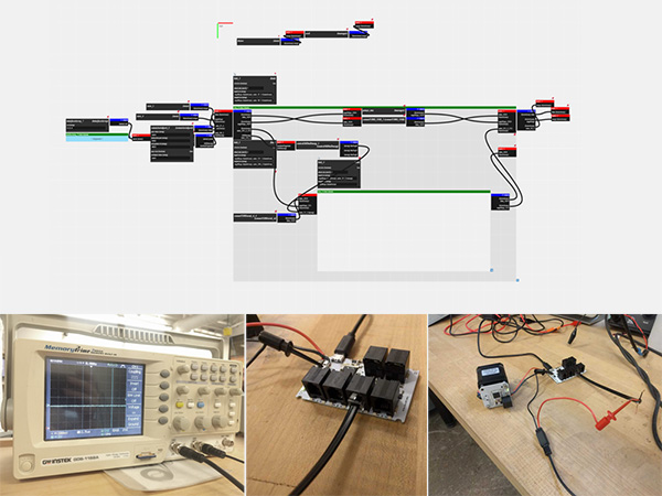
Yesterday, the only way to get the motors to drive was to manually click "enable" for the step driver, then input the position in the array and send it--manually hit "enable" for each new array input. It would accept one movement and then not move again. In the end it was due to forgetting to add in bypass capacitors to the system. From Jake: “when you rotate the motor the driver is drawing current - if you don't have enough bypass capacitance on the 24v lines, this will cause the voltage to drop suddenly, and the motor driver will brown out.” Adding bulk capacitance, saw that the motor was functioning as expected! Then I configured the power distribution board and the motor continued to work in this configuration.
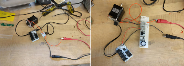 Troubleshooting motor
Sunday, Nov 24th
Claw
We milled and soldered the servo board, and laser cut pieces from plexiglass for the final claw, which we assembled and was ready for testing.
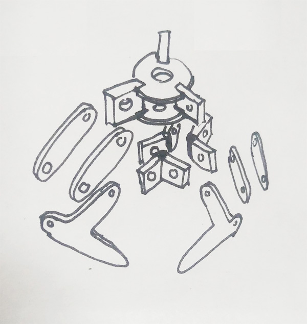 Exploded diagram of claw assembly
 Stencil instructions
Horizontal Axis
At the IDC, our prints succeeded, but we needed to print a couple more, so that was done once again at the IDC. The rest of the assembly was completed on the main portion of the carriage and the horizontal axis.
Housing & Design
We milled the two files on Sunday and sanded the onion skins off. We also sanded the balloons molds to get rid of the supports.
 Machine housing fabrication
Electronics & Coordination
We milled the PCB for the Claw servo motor. We tested the prototype touchpad and read data from it. We decided the button activation for the Claw should be separated from the touchpad board. We went to EDS office hours to troubleshoot our code.
First we loaded Matt Blackshaw’s code to the board (with the 8th pad commented out). This was successful and gave us an output. The sensitivity of the pads were a little finicky but the multi-meter told us the connections we solid, so we figured this had to do with the lo-fi construction and the threshold values that Matt had customized for this set up. Next the mission was to get this pad to output a X, Y, Z position string (with Z always =0) that we could input into the motors via the cuttlefish system. We adapted Matt’s code to give the following output:
 Mounting motor to the horizontal axis
Monday, Nov 25th
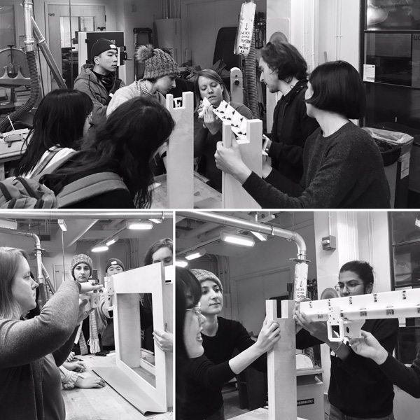
Full Team Meeting & Assembly Dry Run
We met as an entire team Monday to update everyone on small team progress and to strategize. We were able to test assembly tolerances between teams, and to put the finishing touches on the horizontal axis. The claw team programmed servo board and 3D printed the linear servo actuation mechanism.
Housing & Design
Marianna adjusted some plywood parts, and Nof tried to dip cast (?) our cloud balloons. As expected - it did NOT work. we assembled everything without glue and it all fit! We decided it would probably be best to not glue things until we made sure the axis fit into the supports in the box. So we moved the pieces to RPL. We were going to have a meeting at 11:30, so we would probably get to test it then. Now that we made sure that everything was fitting, we agreed the box should be assembled asap - at least partially - so that testing could begin. So we headed to purchase some clear acrylic so the balloons could be contained inside the box - which, at the moment had two gaping holes. We attached the acrylic with epoxy and glued / clamped up the plywood, which again, was pretty easy to assemble due to grooving.
Electronics & Coordination
After the all-hands meeting to coordinate between all teams, we met with Jake to continue troubleshooting Cuttlefish and speaking to our motors. We finalized the wiring layout. We prepared the final files for the touchpad device. Some last components were needed from the 3D prints to finish completely assembling the horizontal axis -- they were completed and assembled. The horizontal axis, and carriage, with the extra z-component were tested in the housing -- and it had a nice, snug friction fit! The carriage was smoothly moving down the track as well!
Tuesday, Nov 26th
Electronics Integration
Tuesday was the final push to integrate the electronics, and to wrap up all testing and remaining coding and fabrication. The claw team redesigned and reprinted the linear servo actuation mechanism and adjusted the servo code to increase the range of motion. The final claw--with button triggered actuation--was tested sucessfully. The touchpad to control the claw's movement was assembled. The wiring connecting power, motors, and the touchpad was integrated into the machine's housing side channels.
Machine Testing
Tuesday night we were able to troubleshoot with the entire machine assembled, test balloons and all! Unfortunately, we were not--at the time of publication--able to use the touchpad to operate the machine.
Pop? It's getting there!