Olafur Eliasson, Your Unpredictable Sameness, 2014
For the final project, I want to build an interface using human body.
Thanks to our best TA Diego, I came to know a program called
Runway ML, a deep learning platform
that does all the complicated process in the black box.
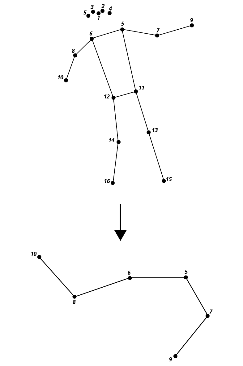
In the Runway, you can load a
posenet library. All output keypoints are indexed by part id. The parts and their ids are:
| Id | Part |
|---|---|
| 0 | nose |
| 1 | leftEye |
| 2 | rightEye |
| 3 | leftEar |
| 4 | rightEar |
| 5 | leftShoulder |
| 6 | rightShoulder |
| 7 | leftElbow |
| 8 | rightElbow |
| 9 | leftWrist |
| 10 | rightWrist |
| 11 | leftHip |
| 12 | rightHip |
| 13 | leftKnee |
| 14 | rightKnee |
| 15 | leftAnkle |
| 16 | rightAnkle |
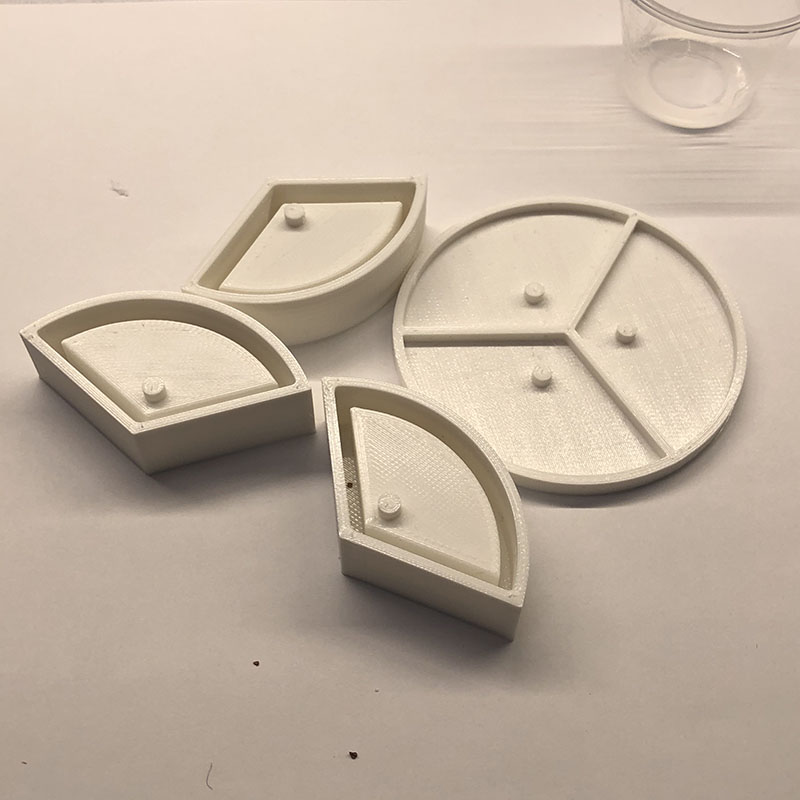
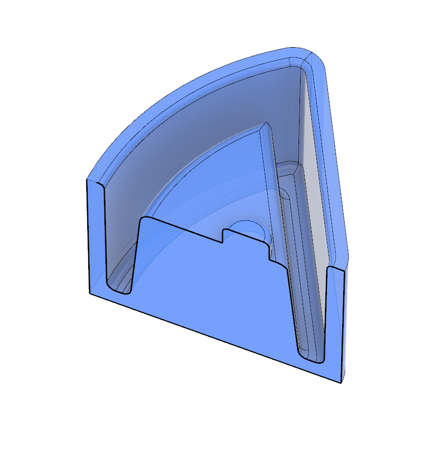
I wanted to make a soft robotic joint actuated by vacuum rather than inflation.
The joint have three chambers that enable omnidirectional movement of the arms.
Major difficulties in working with silicone was first, predicting the exact
behavior of the silicone was close to impossible. I had to go through a number
of iterations to reach the result I wanted. Second, high surface tension made it
extremely hard to control bubbles captured inside the mold, especially when
you are working with relatively deep molds. Especially when working with
3D-printed molds,
you have to be very careful about the air leaking out into the silicone from the
tiny cavities inside the molds.
degasing
...and more degasing
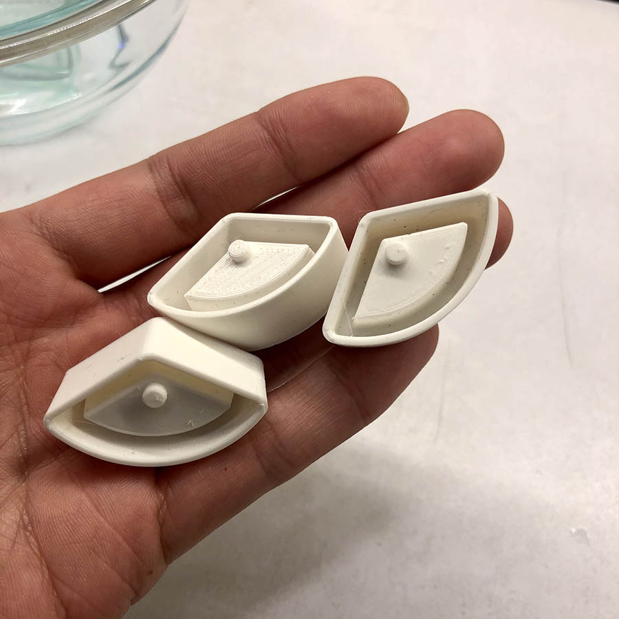
1st Iteration
I printed the molds in Prusa Original using the 0.15 OPTIMAL setting in the slicer,
with the infill density of 50%.
Prints seemed like they are done nice and clean.
a little bit of craft...
After they have been cured, there was a problem while demolding them.
First, the friction between the silicone and the mold made it impossible to pull the
silicone out of the mold. I ended up tearing all of the casts while demolding it.
I decided to make the wall slightly tapered for the next iteration.
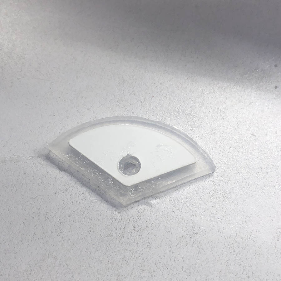
2nd Iteration
For the 2nd iteration, I designed the mold
with the interior walls and outer walls tapered 5 degrees and 1 degree respectively.
Also, I tried to find a specific cast release agent that Ali suggested
(Ease Release 200),
but they were sold out, so I just bought a similar one,
Castin' Craft Mold Release spray.
However, there was another problem with the bubbles; there were simply too many
bubbles even after degasing thoroughly before pouring the silicone.
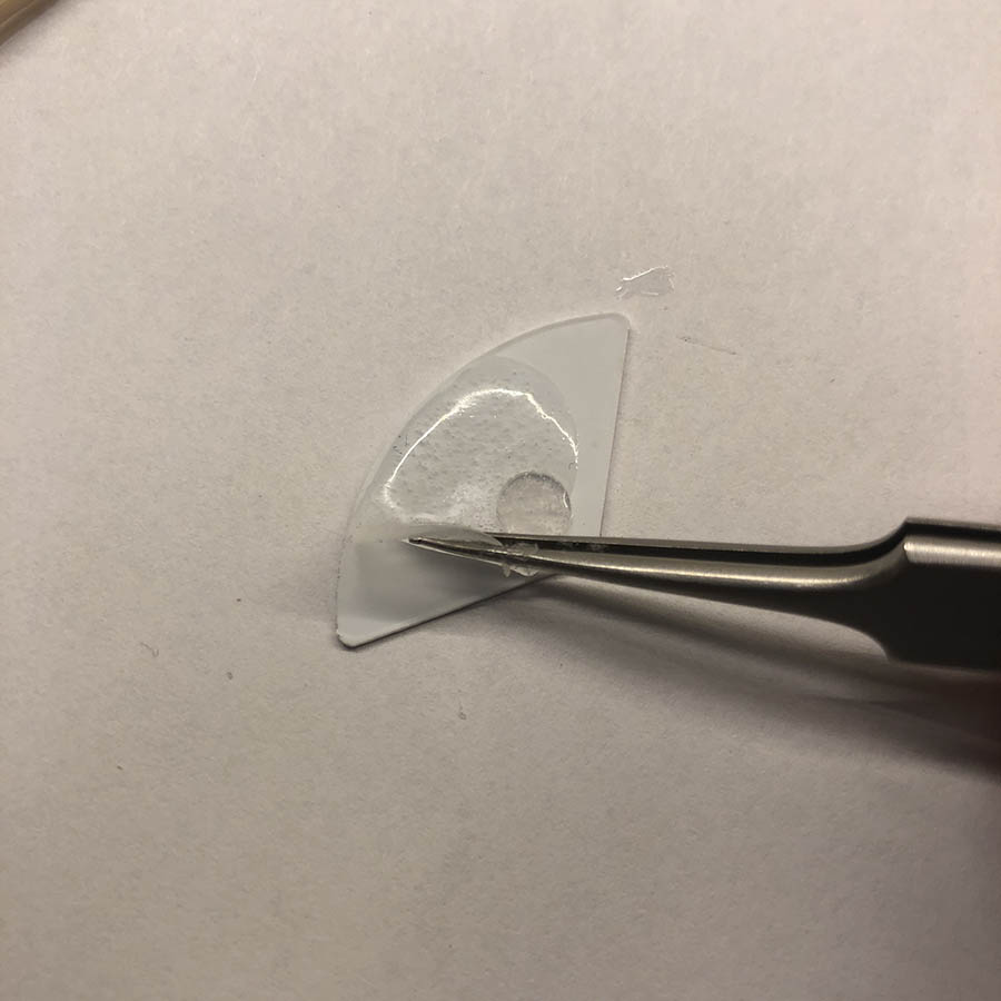
Ali told me that it might have to do with the cavity inside the 3D printed mold;
as it gets vacuumed, the air inside the mold leaks out into the mold.
3rd Iteration
I used the same shape but printed with 100% infill settings for my 3rd
iteration. It took only 10 minutes longer to print the single mold than 50% infill, so not too bad.
The molds still created bubbles but definitely much less than the 50% infilled one.
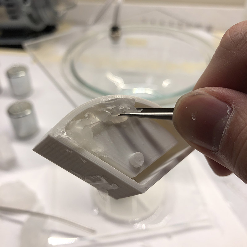
Then I soon realized that it is much better to not use the vacuum at all for degasing
after you pour the mix into the mold. As long as you pour it with extra care,
it would be much less time-consuming and creates less bubbles.
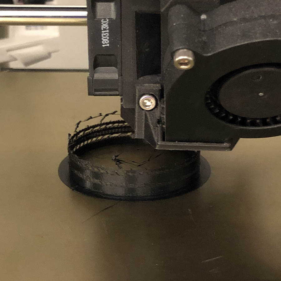
Then I was finally able to test the actual behavior of the silicone.
The contracting behavior of silicone joints was along the horizontal axis
rather than vertical.
First, the walls became too thick when I was trying to taper them, which made it
more difficult to contract vertically. Second, since the contraction happens along
the shortest edge within the volume, it is impossible to reach a vertical contraction
without additional constraints.
These are what I've got so far.
1. Taper the walls for the silicone to released easily of the mold
2. Apply some release agent on the mold.
3. 3D-print the mold with the 100% infill, since the air trapped inside the mold
might leak out into the silicone mix during the degasing process.
4th Iteration
After realizing that the units are not going to contract vertically,
I made constraints to limit the contraction to a horizontal movement.
First I cut a 0.02" sheet of paper to make the constraint pieces.
At first I tried polystyrene sheet for this, but after testing the
compatibility with silicone, I soon realized that the silicone and
polystyrene slides against each other, which made it less effective
to work as a constraint.
So I used pieces of paper instead. Since the paper absorbs
the silicone a slight bit, it adheres better with silicone than plastic.
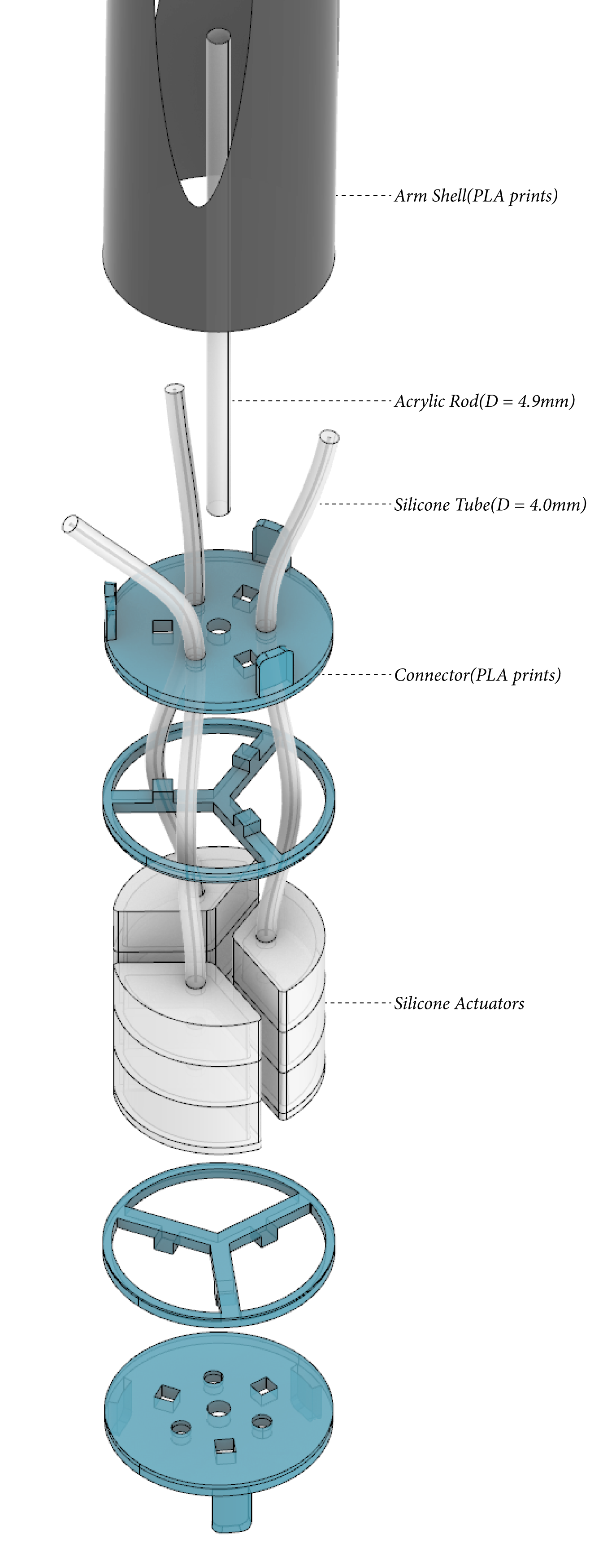
Arms are composed of three parts.
1. Connectors(PLA prints; where the silicone joints are glued)
2. Shell(planned as a rolled plastic sheet, but ended up as PLA prints)
3. Core(Acrylic rod;for structural purpose)
At first I wanted to use PVC pipe for the arm first,
but Ali soon told me that
I would need a huge compressor to deal with such weights.

So I decided to divide into two parts: paper-thin plastic sheet
for a shell and an acrylic rod for a core to make it as lightweight as possible.
I unrolled the surface in Rhino to cut the sheet, and physically rolled it
to make a cylinder shape.

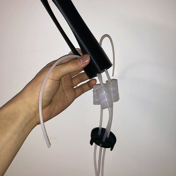
connector and a core assembled
However, I soon realized that it is impossible to roll the paper with oval
shaped opening because the it is difficult to control the actual
shape of the rolled paper. Then I decided to 3d print the arms.
Using Prusa 3D printer, I wanted to make the prints as light as possible.
First I generated a g-code using a solid of 0.15mm thickness, which is
exactly a diameter of the nozzle.
But it seems it's too thin for the print doesn't work because it is unable
to build up all the way up to the last layer.
Then I used 0.2mm thickness and an optimal setting in the prusa slicer.
I ran 4 printers and only half of them came out well.
as lightweight as possible
Now all the parts are ready.
Silpoxy was my friend. Silicone is usually hardly adhesive by any kind of glue, so
the Silpoxy is the only way to glue silicone to the PLA 3D prints.
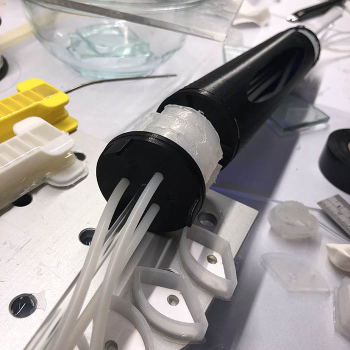
baking silpoxy on a heatbed. Silpoxy takes about 12 minutes to set with heat.
first full-movement test
For the electronics, I wanted to use networking to recieve live stream video to my computer,
and use it as an input for the pose detection library.
First, I wanted to use ESP-WROOM and OV7670 rather than ESP32-CAM, because I wanted to seperate the processor with the camera itself.
I found a nice tutorial
and an example that uses both boards.
I found a esp32 library from a git page
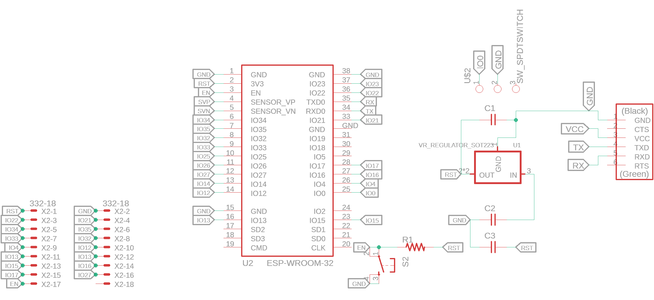
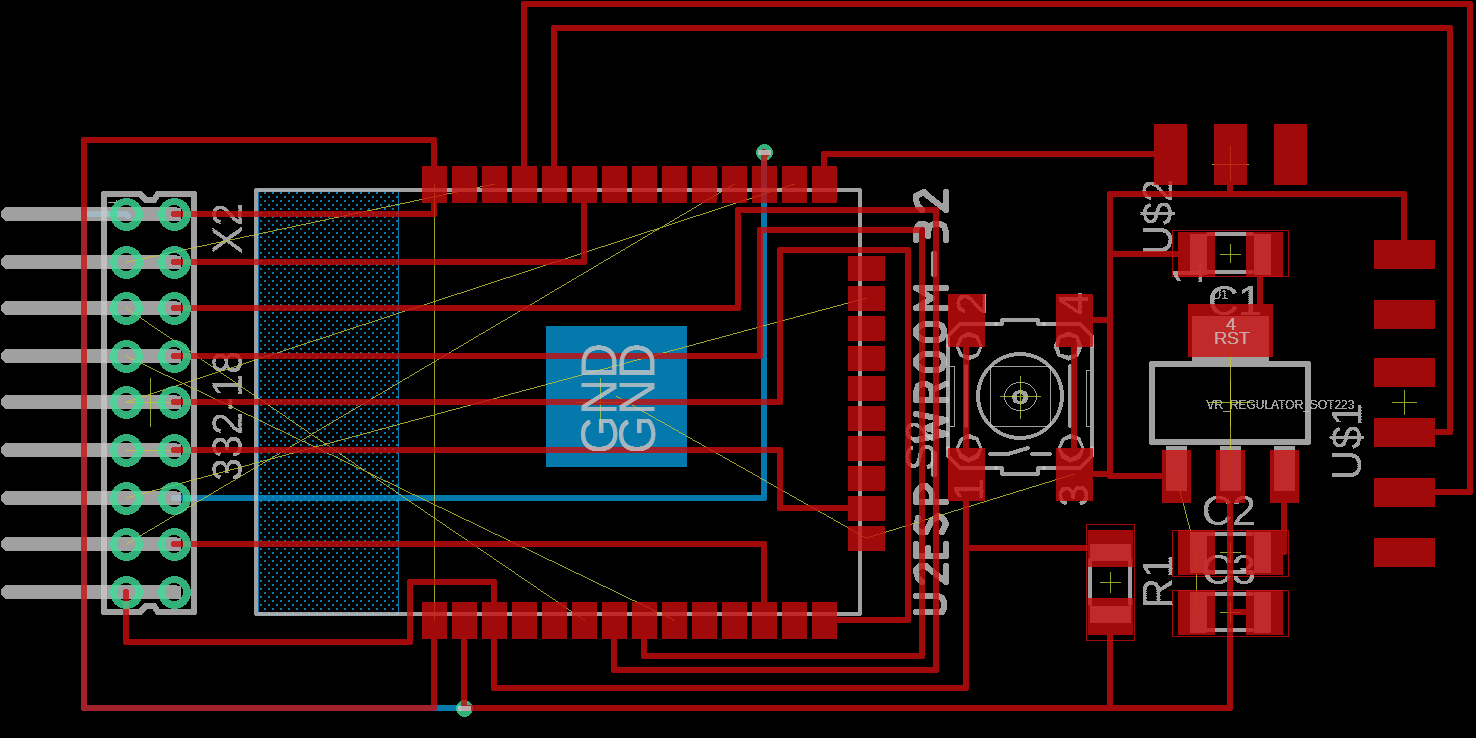
I created a schematics, but I couldn't figure how to unravel all the wires. Also, I figured that the rectangular zone on the left is the antenna,
which should not be interfered with other wires.
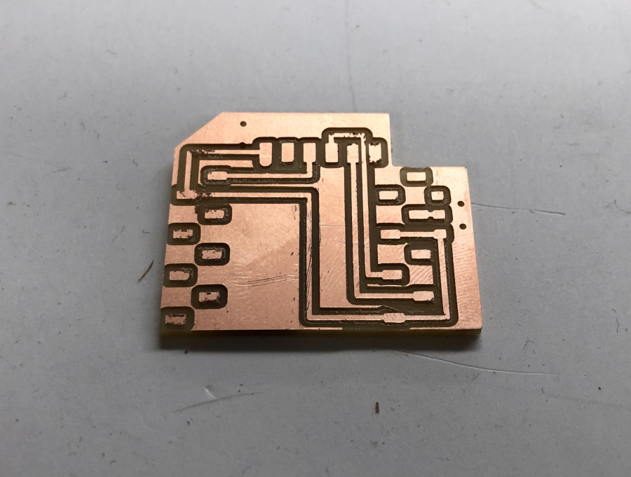
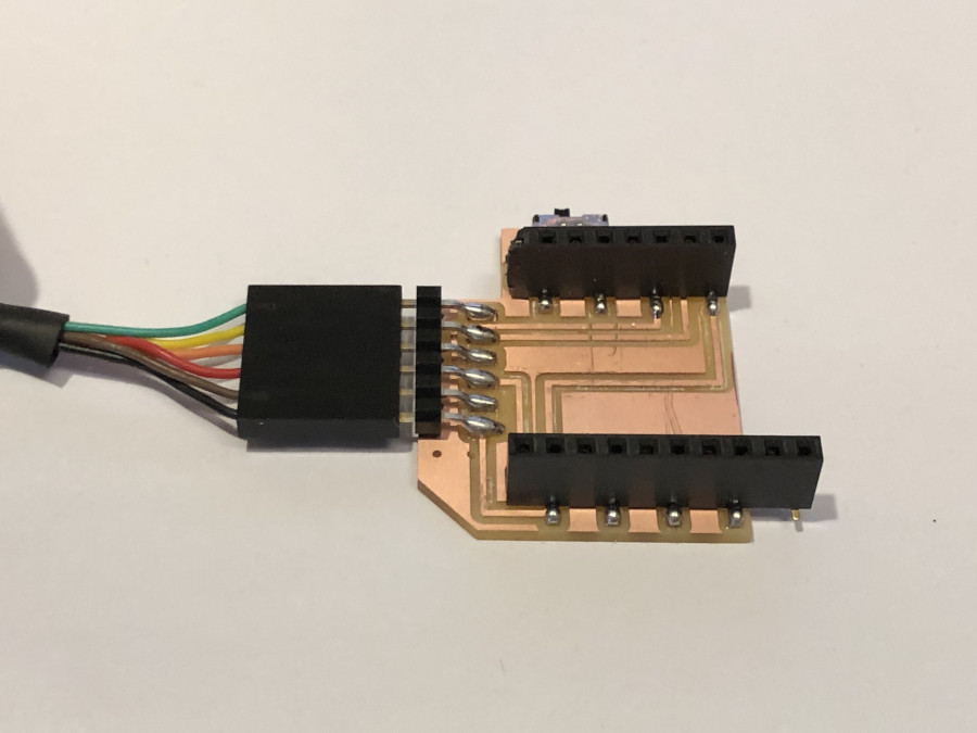
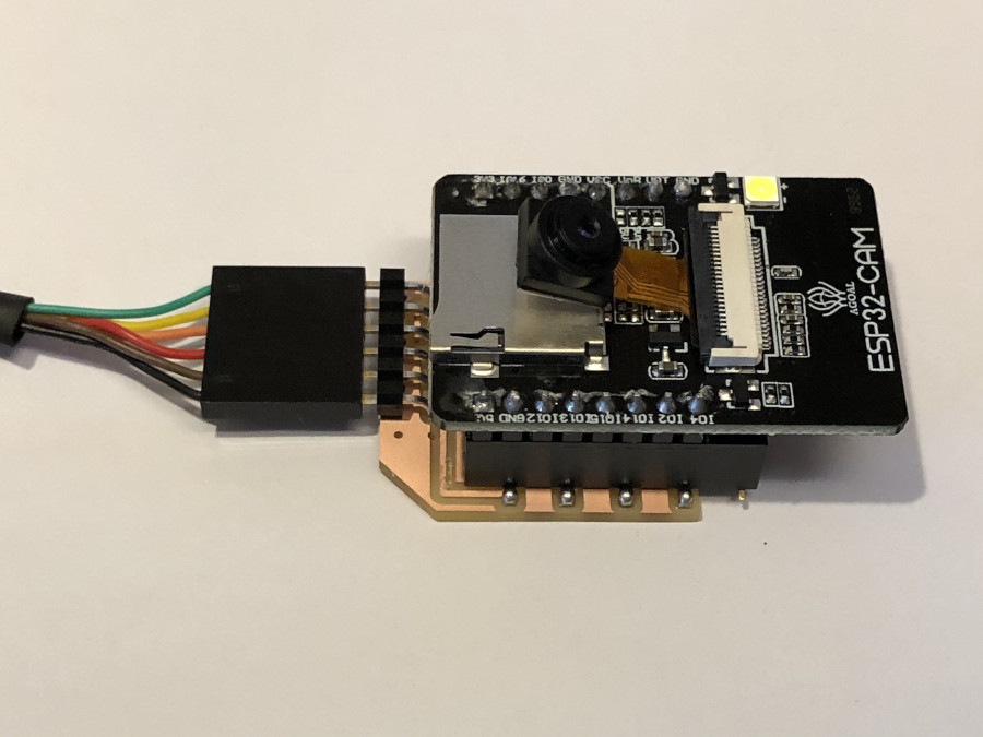
Then I decided to make a simple ESP32-CAM for the input.
I couldn't find a single row 8 pin female header, so I just used 10 pin for one side and used only 8 pins among the pins.
Other than that, milling and soldering was very simple and straightforward.
Troubleshooting
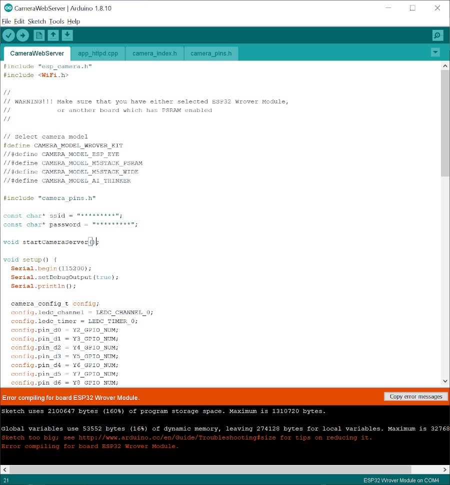
While programming the board through Arduino, I encountered a few errors.
I found a nice website
that covers pretty much every troubleshooting for ESP32-CAM in particular.
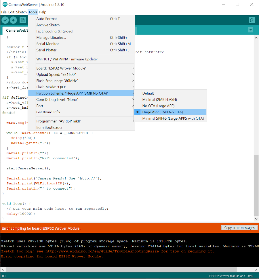
First if you get an error that says something like "Sketch too big",
make sure you set the Partition Scheme from default to Huge APP.
Even after changing the partition scheme, I got an error that says "Failed to connect to ESP32: Timed out waiting for packet header".
I couldn't figure to program it on my computer, so I moved on to a Linux PC at the shop.
As I changed the port to the right one, I was able to write a program.
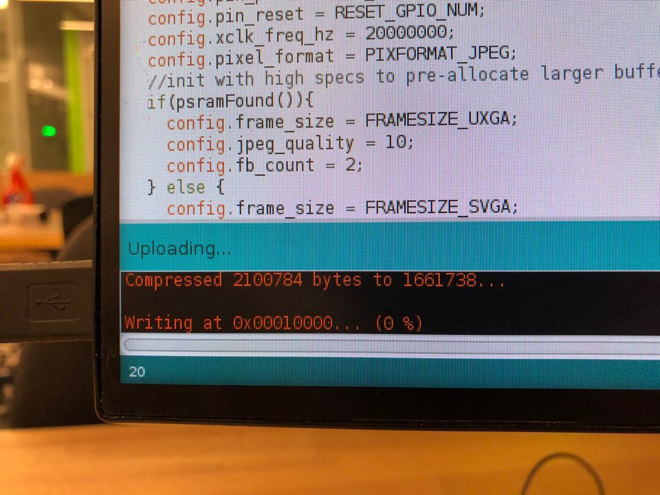
My windows PC just doesn't recognizes my boards all the time. So I used my 7 years old macbook pro and it worked fine.
As I pushed the reset button, the serial window gave me a bunch of glyphs.
When this happens, make sure to set your baud rate to 115200.
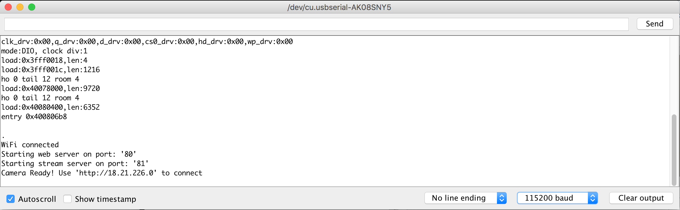
Now it says "Camera Ready! Use 'http://18.21.226.0' to connect", which seems happy.
After I failed to figure out how to connect the ESP32 webstream image and
the RunwayML environment, I tried to create a GUI to control the tippoint of the
column real-time. I used Processing to create a GUI to select a point in a window and
find a path to reach that certain point within the range that the tip of the
column can reach. Using the communication protocol in Processing that Ali had developed,
I was able to relatively easily send commands to the board through the USB port.
However, as the column turned out to be not too rigid and robust,
I changed the plan to make a self-stabilizing column.
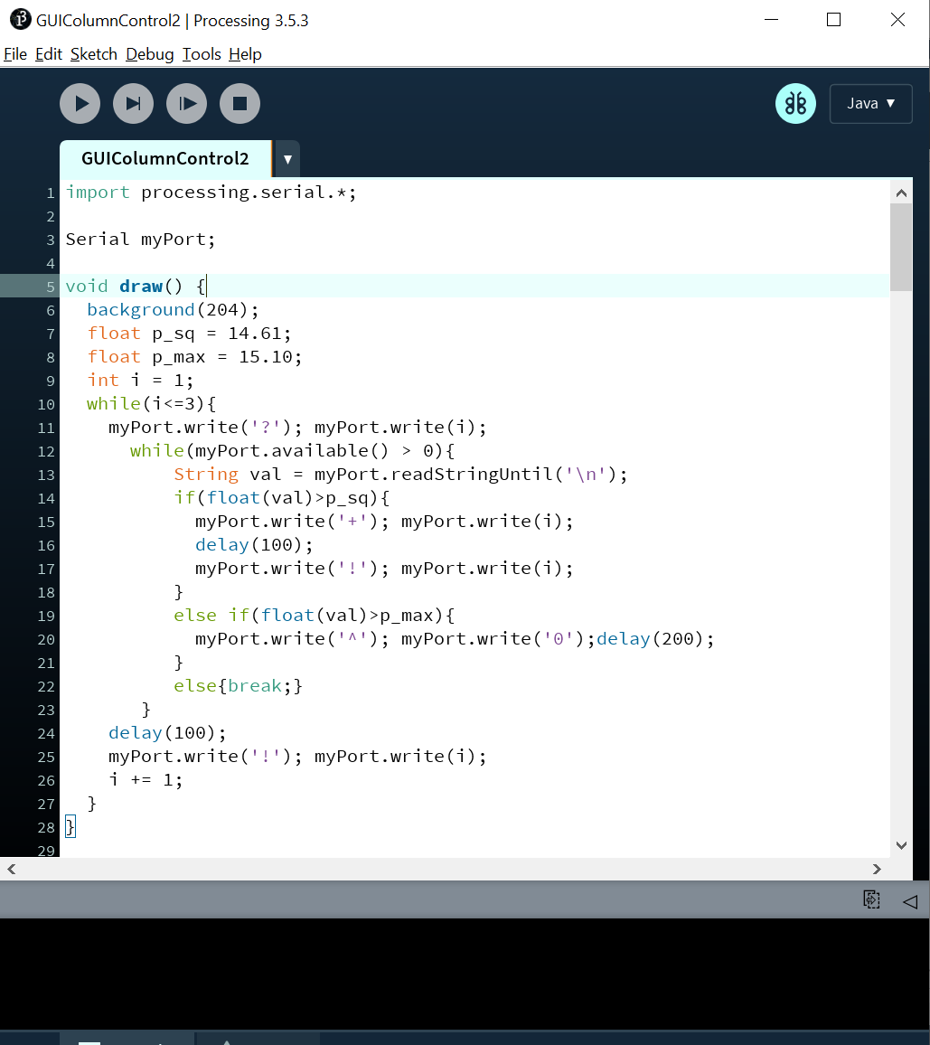
The following lines of code makes the column the stand up even
when tipped over.
First of all, the code measures the pressure value of the chamber
by sending '?i' (i being the index of the chamber) thorough the
serial port. Ali's module was able to sense the pressure only
one port at a time, so I made it to open and close the port rotating
around each chambers every 100ms.
When the column is tipped over to one side, the air chamber on that side
gets squeezed, yielding a slight jump on the pressure.
A global variable p_sq defines a threshold that can tell that there had been a
tipping action, which then trigger the inflating actuation of that certain
chamber. p_sq worked best when set 0.1PSI higher than the atmospheric
pressure. Another global variable p_max defines a maximum air pressure.
When the pressure goes higher than p_max, the air is released
from the chamber. p_max prevents air chambers from inflating more than necessary.