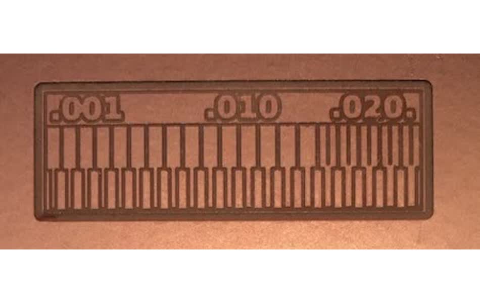
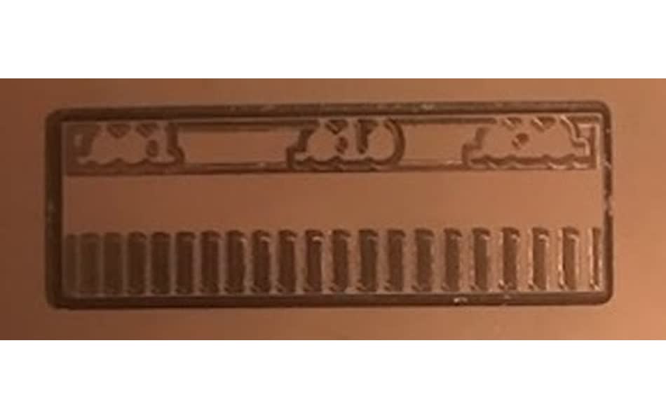
mill characterization
We'll use the Roland SRM-20 to mill the PCB traces. Before diving into milling the programmer, we characterized the milling machine and tools. We have two different sized endmills available: 1/32" diameter and 1/64" diameter. To get an idea of how fine of resolution each endmill can handle, we use the following trace.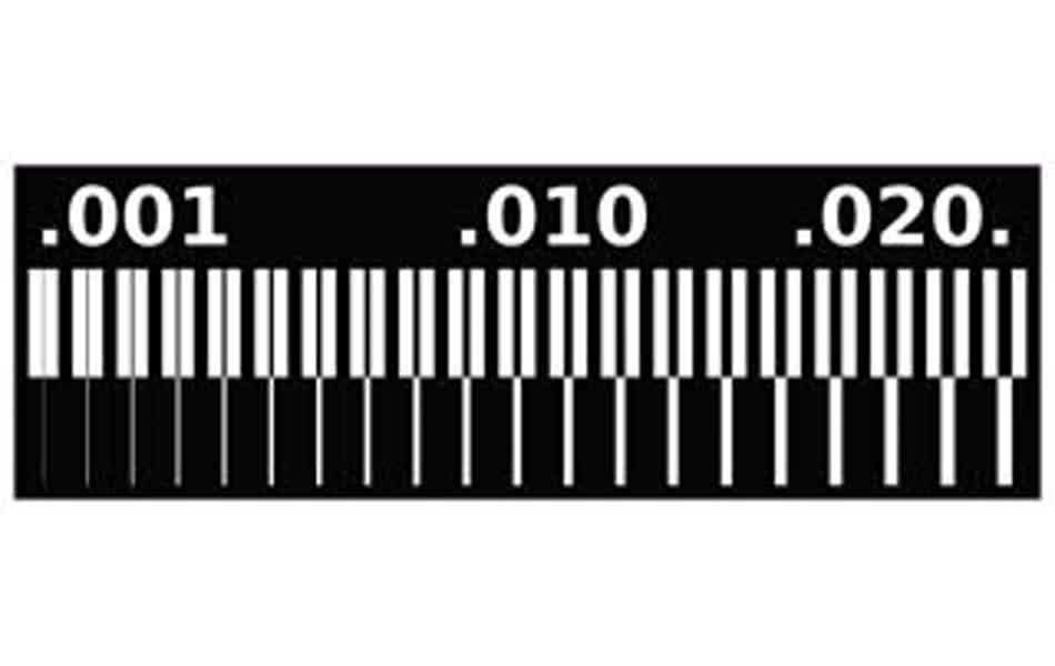
Neil designed mods to accept .png as input for the Roland SRM-20. Once the image is loaded, there are three parameters that you can adjust:
- cut depth (inches): the depth (z-axis) that each pass with cut into the material
- max depth (inches): the final depth you wish to cut to. By adjusting max depth and cut depth, you control how many passes the endmill should make along the same trace.
- offset number: the number of passes that the endmill makes along the outside of the design (cuts into the black, leaving behind the white pattern)
Only the 1/32" endmill is used when cutting the outline, but when I ran the first test the max depth was not set large enough to cut all the way through the substrate. However, I didn't notice that until I had already removed the substrate from the sacrificial layer so I was unable to rerun the job with a deeper depth because the alignment would be off. I found that the max depth needs to be increased to 0.096 inches with a cut depth of 0.024 inches in order to cut through all of the substrate.
As you can see, the 1/32" endmill isn't able to cut any of the inside lines because the tool tip is too thick. This makes sense since the diameter of the tool tip is 0.0312 inches so it's unable to mill away an area less than this size. Similarly, with the 1/64" endmill the diameter is 0.0156" so only the 5 largest subtractive lines are milled.
FabTinyISP
building
Following Brian's documentation here, I built the FabTinyISP. Using the design provided, I kept the cut depth and max cut depth at 0.004 and set the offset number to 4 to mill the PCB.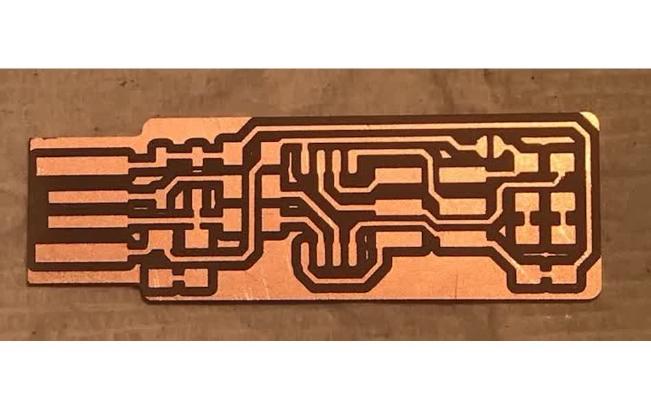
Following Brian's circuit schematic, I soldered all of the circuit components onto the board.
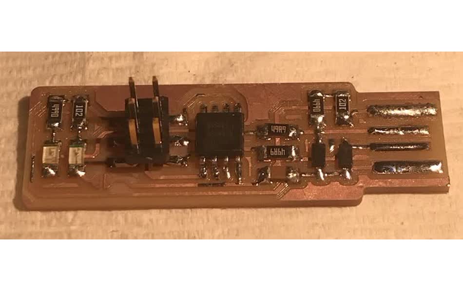
Soldering was fun and tedious, but I started to get the hang of it. This is the first thing I've ever soldered and I think it came out alright. The goal is to make the joints very smooth and shiny - not gnarled or looking like a mereungue. I found it easiest to use extra flux.
But I realized that I forgot the solder bridge that allows the programmer to be programmed...
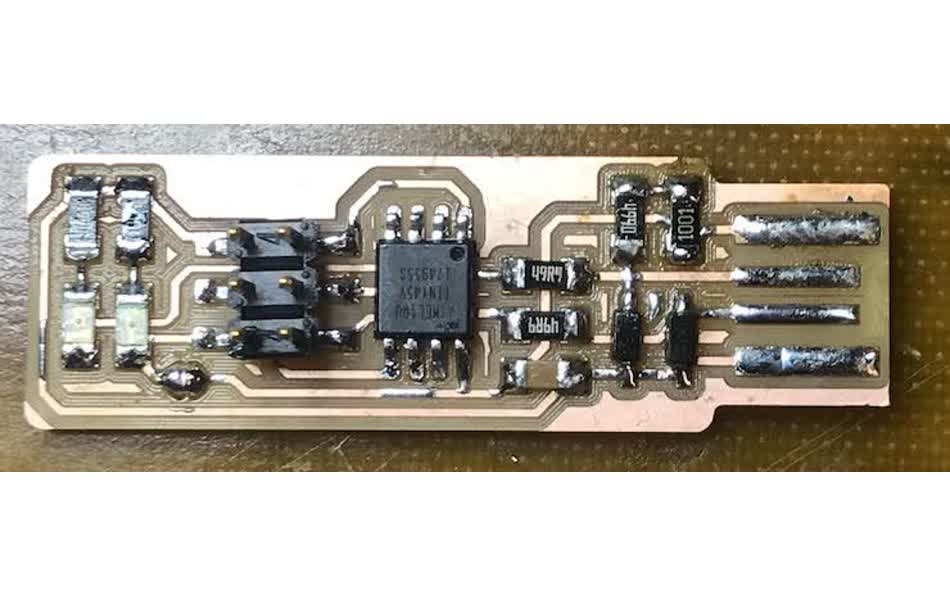
And then it finally started to click what is actually happening here. The freshly soldered programmer is still only a "programmee" because as of now it's just an empty ATtiny45. Adding the bridge connects the V_cc to the V_prog pin on the ISP header so that I can connect another programmer to the board that will program the ATtiny45 to act like the FabTinyISP that we want it to be!
programming
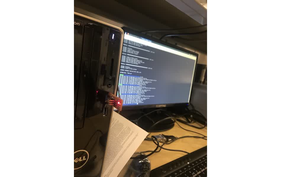
So now that the board is built, we need to program it to be a programmer. I installed CrossPack as instructed on Brian's page and followed the process for programming the programmer :: (1) I changed the programmer to "avrisp2" in the makefile, and (2) ranmake flash, but my computer wasn't able to find the usbtiny at all.
I have a macBook air with only a USB-C port, so I was using a converter to program with the USB. However, Neil mentioned in class and Brian's page points out, that the USB 3.0 converters may not reocngize the usbtiny because they have a much faster clock speed than the ATTiny45. I tried all different converters, making sure to use USB hubs with 2.0 USB type B ports:
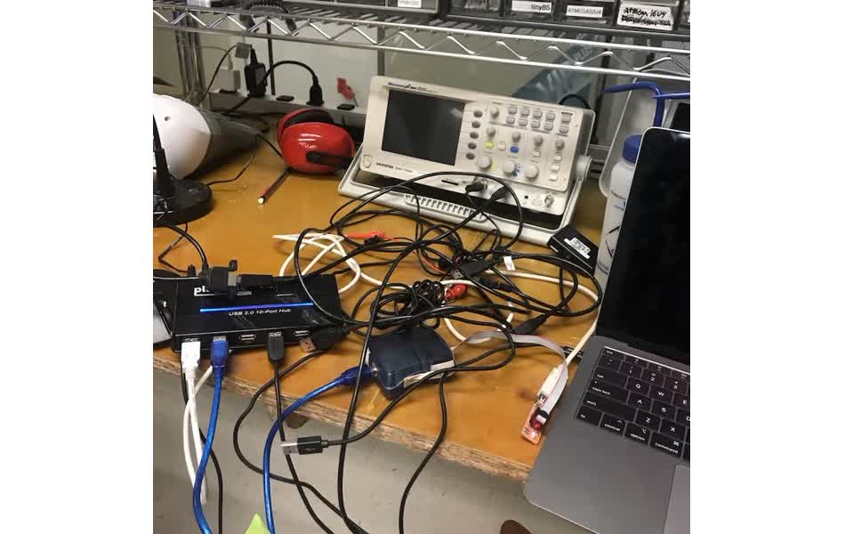
No combination of converters would recognize the USB on my mac, so I switch to trying to program on my linux machine to make sure it wasn't an issue with the actual board.
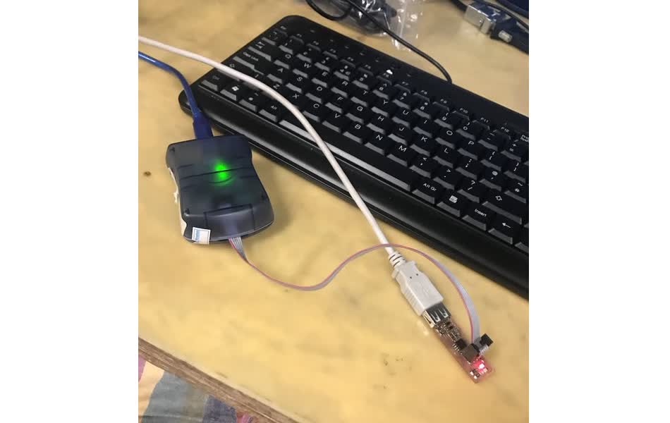
After installing the avr-gcc libraries, I was able to follow Brian's programming instructions smoothly and my fabtinyISP is up and running!
I'll need to figure out what's going wrong with my mac setup later . . .