Safety data sheets
It's important to read safety datasheets!!PDMS safety
SDS for baseSDS for agent
TDS (technical data sheet)
highlights
- PDMS cures without exotherm at a constant rate regardless of sectional thickness or degree of confinement.
- Not compatible with anything containing Organotin or sulfur.
- It's reccommended to do pouring/dispensing under vacuum if you have small parts.
- 1.5 hour potlife. ~30 min cure time around 100 degrees C
- Do not store with strong oxidizing agents
- Nitrile rubber gloves are sufficient hand protection.
Oomoo safety
SDS for agent and baseTDS for oomoo 25
highlights
- 1:1 volume mixing of Part A and Part B
- 15 minute potlife (time between mixing and setting)
DryStone Safety
Drystone SDShighlights
- Do not rub eyes if dust gets in them.
- Becomes very hot when mixed with water - do not use to mold on body parts, they will burn.
- incompatible with acids.
- DO NOT wash down the drain.
3D CNC
Designing
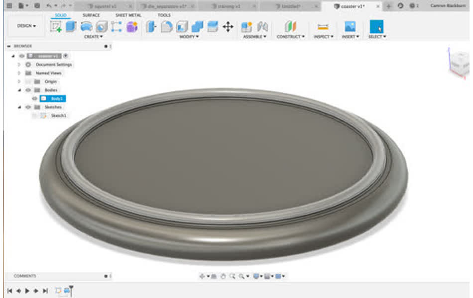
Since most of my week was absorbed with laser micromachining and solft lithography molding, I need something simple and straight forward to mill on the desktop shopbot. I had really wanted to experiment with food safe material to make chocolates, ice cubes, jello, jello shots, etc. Food seems like a great thing to make a mold for because you can reuse each one for so many different things. BUT alas I ran out of time (Neil mentioned supply vs demand time and planning management today - I need to get more organized with demand planning), but luckily Reynolds is a place and I can always revisit food safe molding around the holidays or something.So, I decided to make a drink coaster - it's something that's useful to have more than one of so molding is convenient, has a fully flat side to make it simple to mill on the shopbot, and can have a lot of variety in appearance from the same mold (drystone, paint cured drystone?, add paint or powder color to liquid drystone?, clear epoxy with different objects cast inside it . . . )
CAD simple design in Fusion 360
Machining
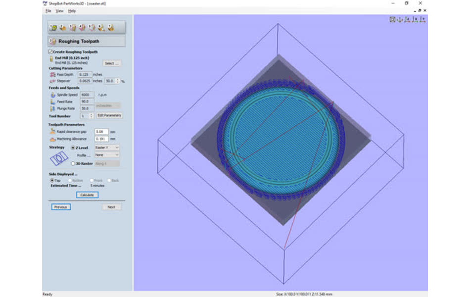
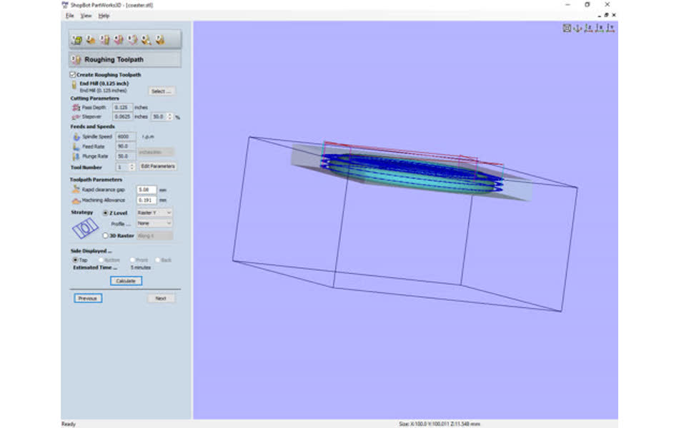
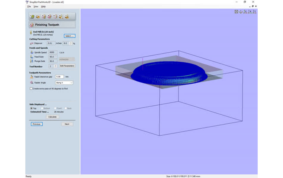
export as .stl file and then load in PartWorks3D to generate the toolpath for the shopbot.For efficient milling, you generate a rough pass toolpath first the has large step sizes and cuts away the majority of the material.
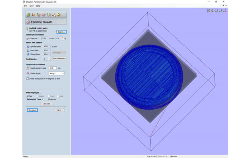
Then, you generate the finising toolpath that will go much slower with smaller steps to smooth out the surface and corners. The stepover determines how precision the finishing path with be, but smaller stepover requires more time. I set mine to 8% (0.01 inches) which gave an estimated mill time of about 30 min.
The desktop shopbot runs pretty much the same as the one from "make something big" week.
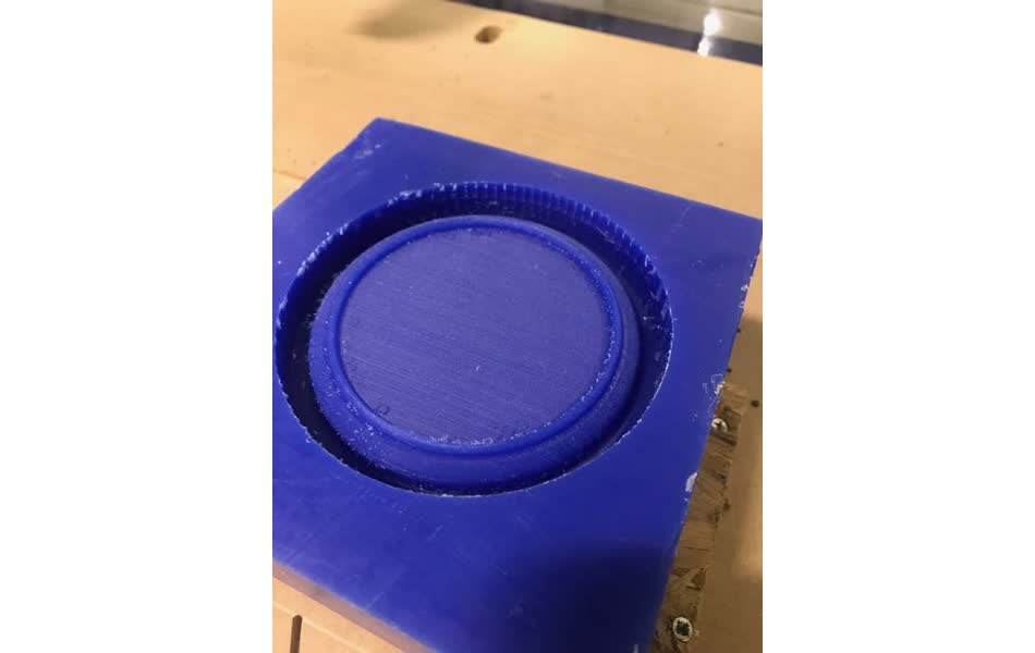
The estimated time was off by a factor of 2 - the whole job took a little over an hour when it was estimated to be 30 min.
but it finally finished and came out very smooth!
Molding
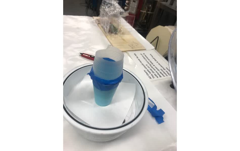
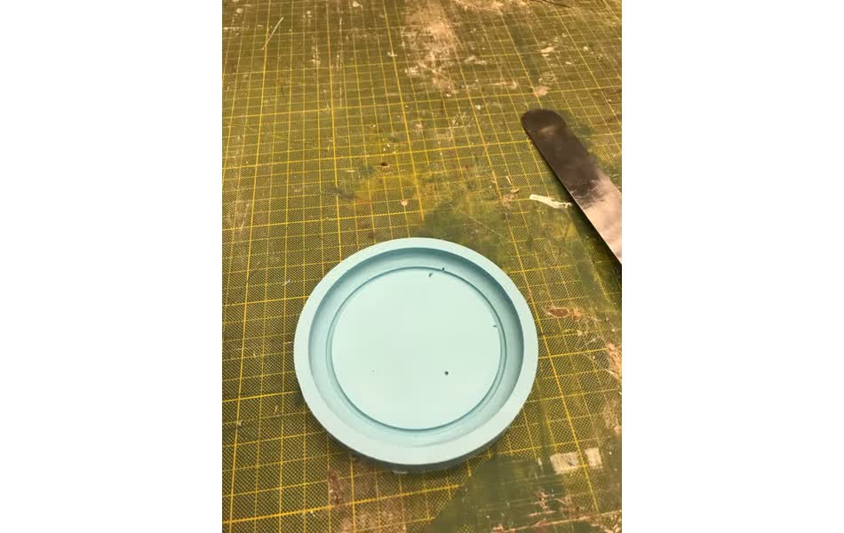
Now it's time for oomoo and drystone.I mixed equal part A and B for about 4 minutes, minimizing for air bubbles in the mixing and making sure everything's equal color. Then, I put the mixture in vacuum to remove any remaining air bubbles. The air in the oommoo will cause it to expand and eventually pop, so I tapped an extra cup on top of the mixing one to make sure that it wouldn't overflow in the vacuum.
Then I poured it into the wax mold and let it sit over night.
Coming back to check on it in the morning, there were a lot more bubbles than I expected at the top of the oommoo mold - I think this is because the vaccuum pump wasn't fully vacuum and I poured the oomoo too close to the end of it's potlife. It was pretty easy to pull out of the wax, and unfortuantely there are bubbles in the mold as well.
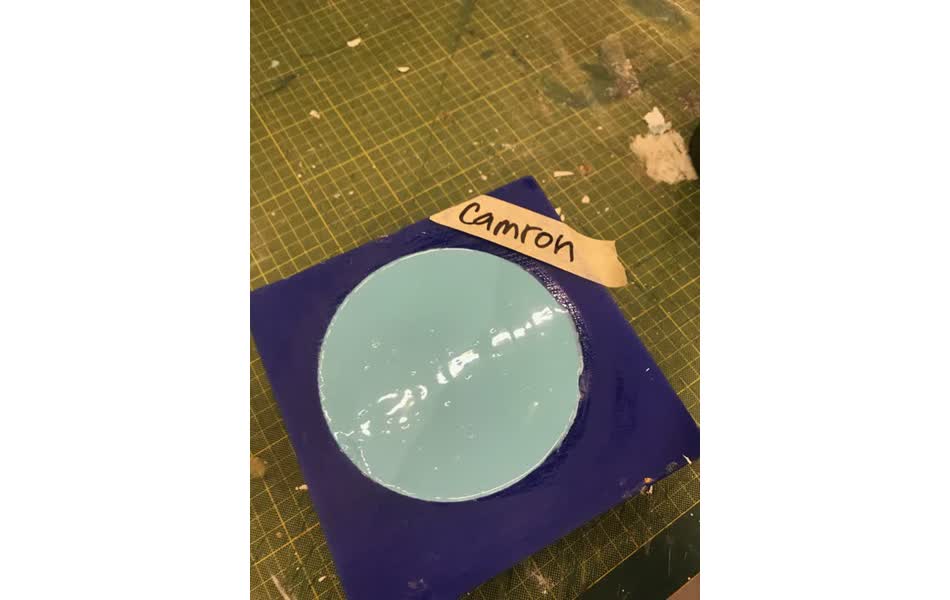
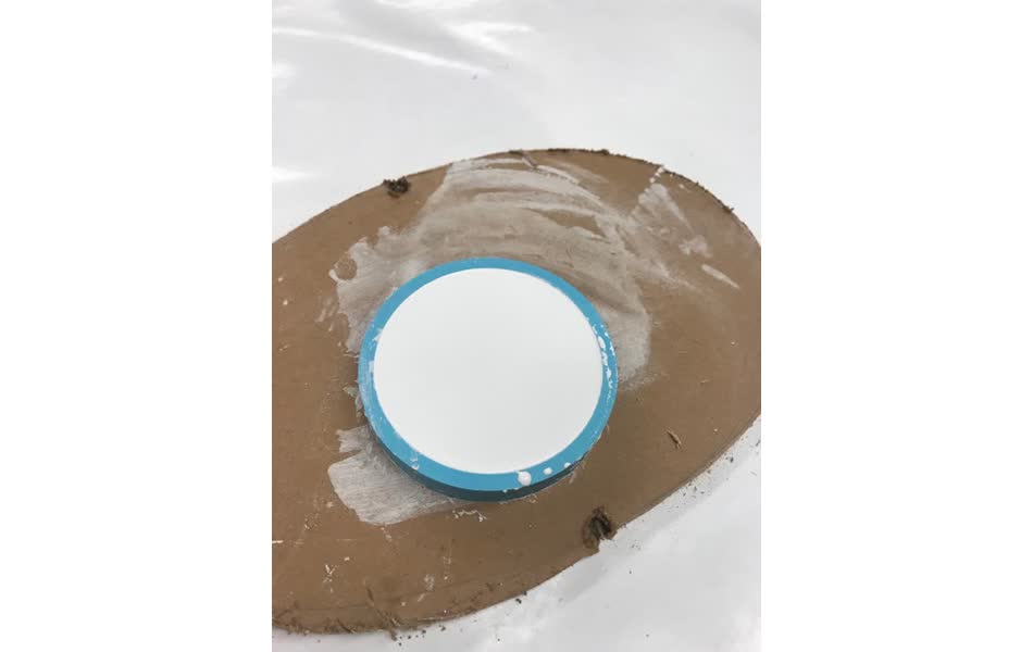
Moving forward with the imperfections, I mixed some drystone using the "island method" that Graham taught us - start with a bit of water and sprinkle drystone in until there's enough of it to form a dry island at the top of the water, then mix until it's smooth. To prevent from bubbles forming at the bottom of the drystone, I "painted" the small crevices of the coaster with a thin layer of drystone before pouring it intil the whole mold.
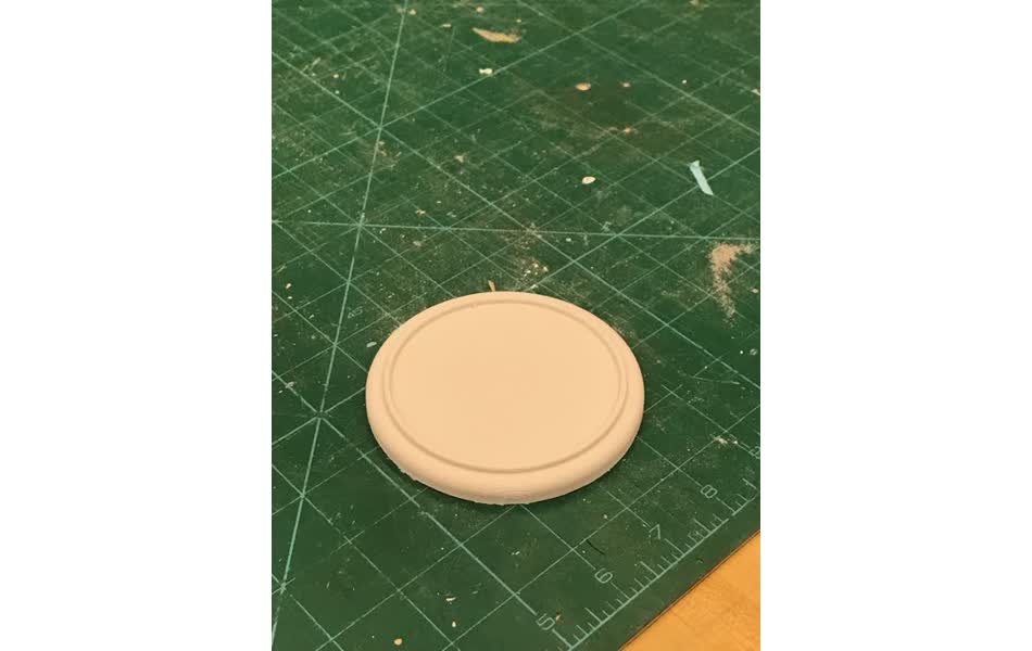
I let it sit for about two hours. The drystone did get warm while it set, as it states in the safety datasheet. Then, the coaster was ready!
Molding microstuctures (with laser micromachining?!)
I made microfluidic devices in the 2.675 micro/nano lab class that I'm taking. We molded them with PDMS on a silicon wafer masters that had been prepared by the course TA with a lithography and dry etching process. my goal is to recreate some of these experiments without the photolitho masters - instead using the process of multi-lamina assembly of laser micromachined laminates (MALL) developed with Prashant in his thesis. Most of the devices that we made had a 1:1 aspect ratio (~200 um deep channels with ~200um thickness), which MALL should be more than capable of replicating.Laser micromachining
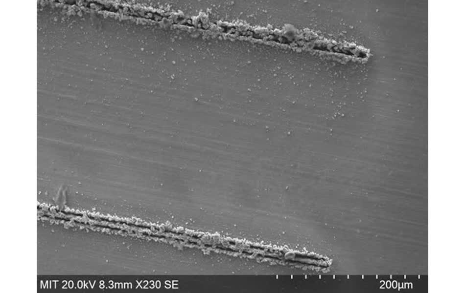
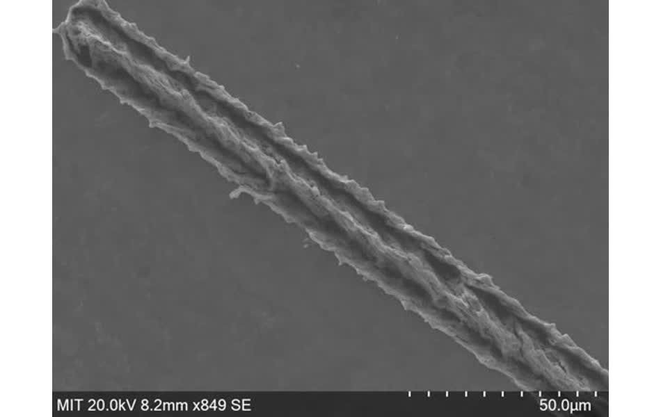
To start, I experimented with 100 um thick brass. I machined circles, lines, and rectangle of varying shape and thickness with different speed and power values. Below are SEM images of some with machine parameters.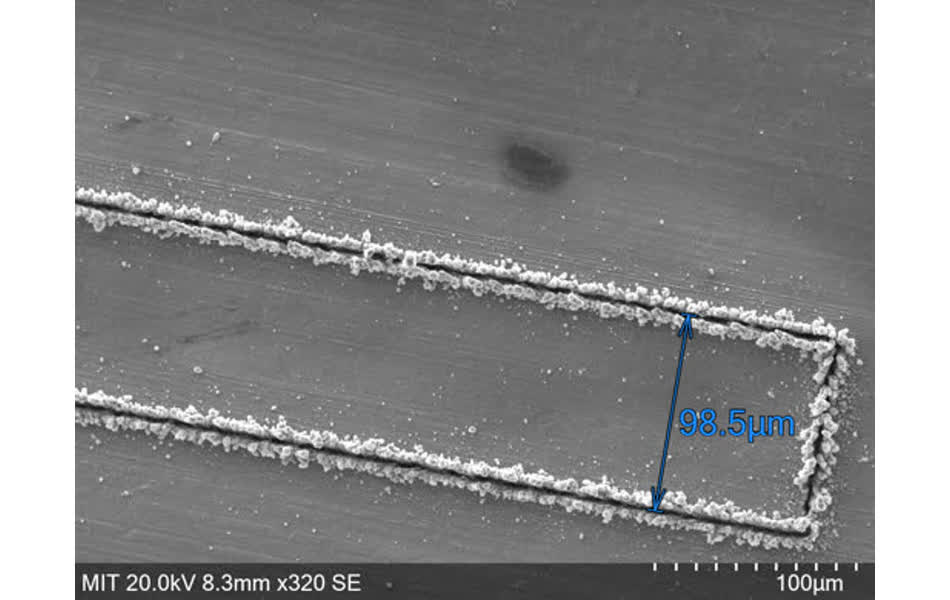
100x500um rectangle at 0.01 um/s feed rate, 10% power, 1 pass
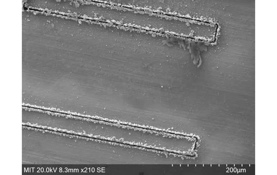
50x500um rectangle at 0.01 um/s feed rate, 10% power, 1 pass bottom, 2 passes top
10x500um rectangle at 0.01 um/s feed rate, 10% power, 1 pass bottom, 2 passes top
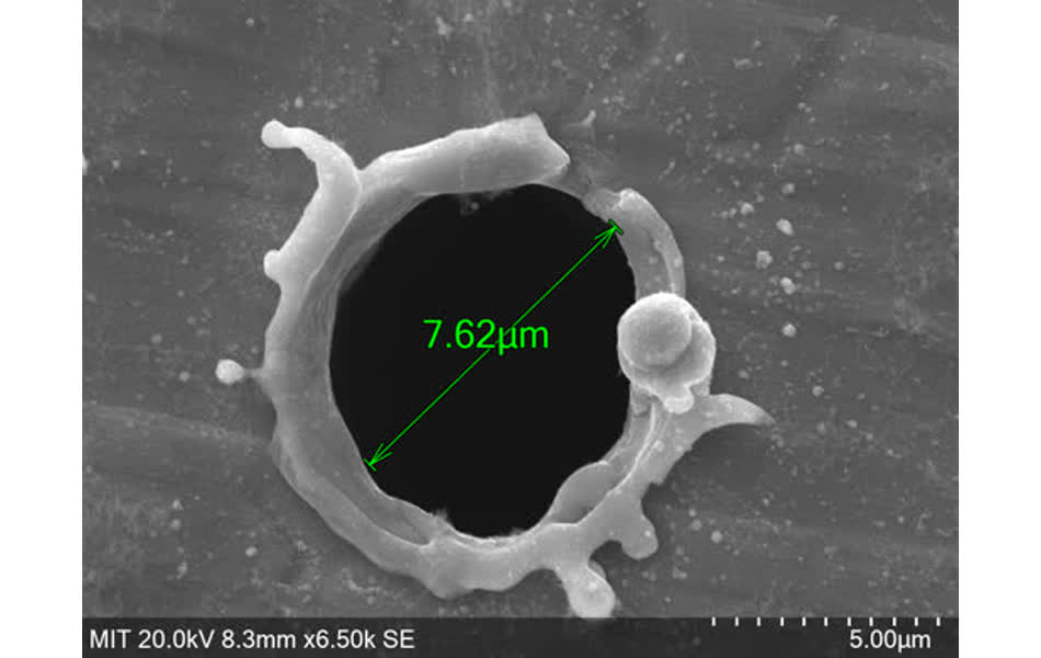
percussion hole at 0.2s, 10% power
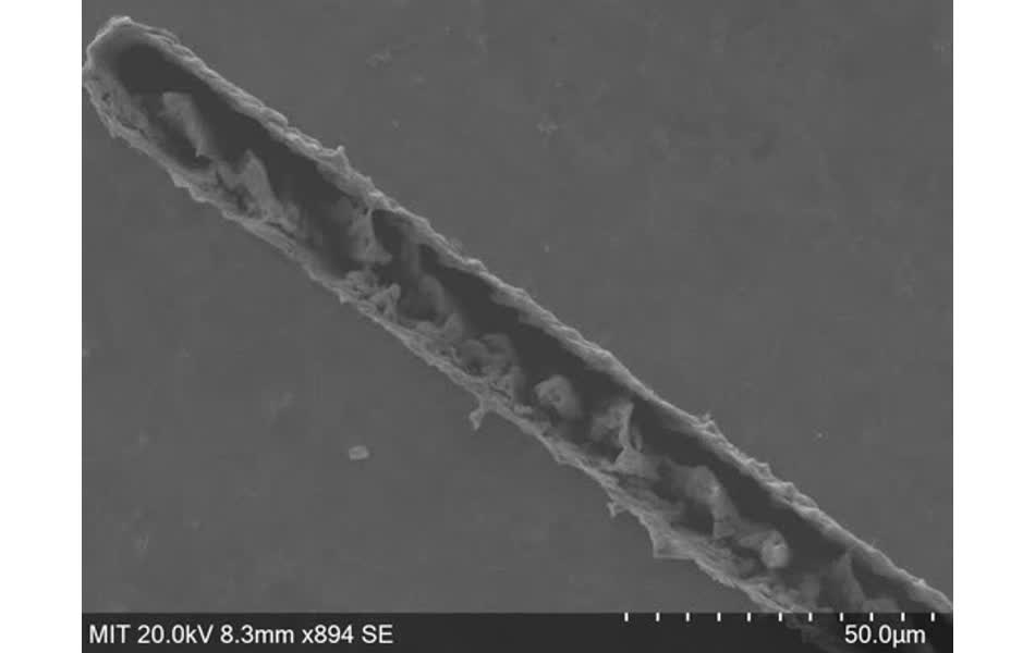
Then perform the electrodeburring step, also developed by Prashant. This removes the micro-burrs along the edges of the machine path without harming the pattern. It's similar to electropolishing - I attached the patterned brass to the anode and a scrap piece of brass to the cathode, and put them both in phosphoric acid at 5V for about 30 seconds. Similar cuts after deburring:
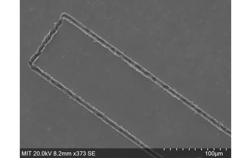
100x500um rectangle at 0.01 um/s feed rate, 10% power, 1 pass
10x500um rectangle at 0.01 um/s feed rate, 10% power, 1 pass bottom
10x500um rectangle at 0.01 um/s feed rate, 10% power, 2 passes
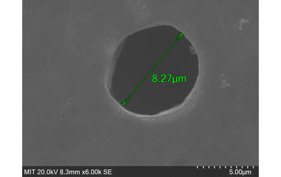
percussion hole at 0.2s, 10% power
Molding with PDMS
Will the tiny features made on the oxfrod be picked up by the PDMS mold? How clean and smooth will the edges come out to be??I mixed the PDMS 1:10 agent:base by weight. Then put the mixture in vacuum to remove bubbles. Then slowly poured it over the patterned brass.
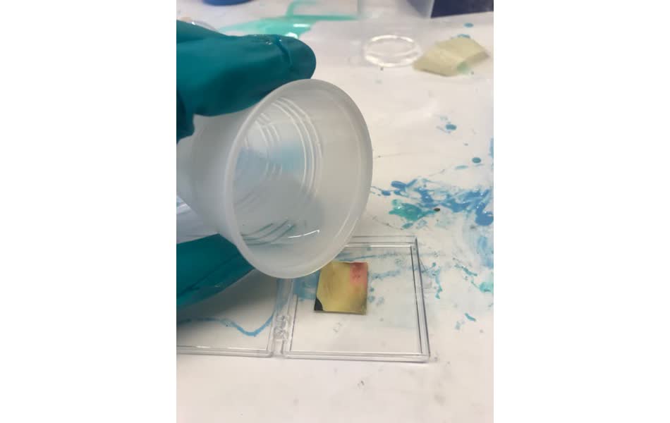
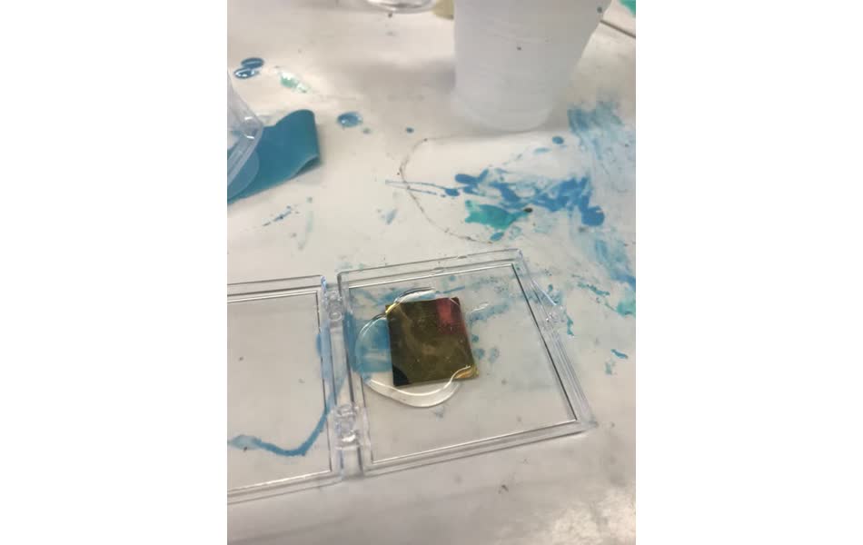
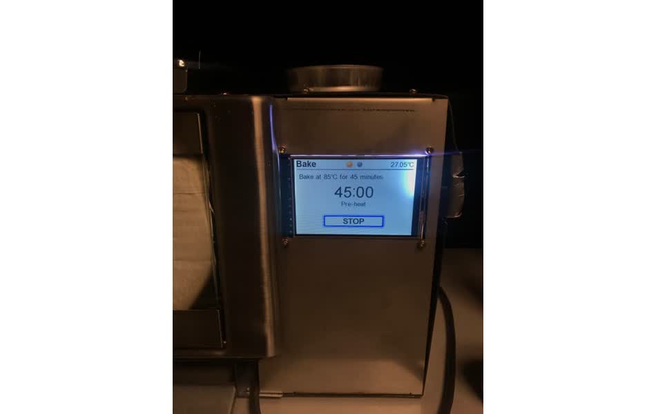
To speed up the cure time, I put it in the oven at 85 degrees celcius for 45 minutes.
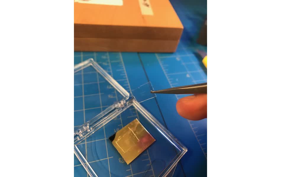
Once it's ready, I cut out the mold. You can just faintly make out the patterns by eye.
Under the optical microscope, you can see that all of the matterns transfered to the PDMS, even the rough edges and corners that were missed in the deburring process.

I'm curious to know if the rough edges will cause problems in the microfluidic devices by introducing more turbulent flow. unfortuantely, I ran out of time to explore further and actually replicate the microfluidic blue prints that I modeled in Fusion, but I hope to come back to it eventually.
electrophoretic dye separator: .svg, .dxf, .pgm
laminar flow through squirrel drawing: .png, .svg