board design
determining components
I'm going to use the ESP32 since there's been a lot og hype about it aorund the class, it has a lot of documentation and online reseources, and it seems like a very useful chip to get to know. I'm going to hook it up to a adafruit BNO055 breakout board to easily return orientation data (it does all the sensor fusion calculations on the chip to immediately return absolute position). I'm a bit confused using the breakout board becuase Im' not sure how to approach soldering it, but we'll see how it goes . . .starting with the schematic . . .
I created Eagle footprints for the new devices
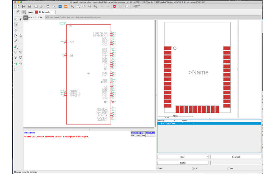
one for ESP32-WROOM
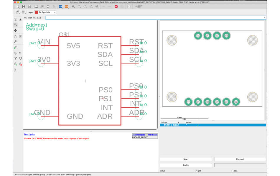
and another for the BNO055 adafruit breakout . . how will this guy look on a board ??
now time reverse engineer the HUZZAH32 feather that I had been testing the WiFi connection with and Neil's ESP32 helloworld to figure out what extra passive components are needed on my board.
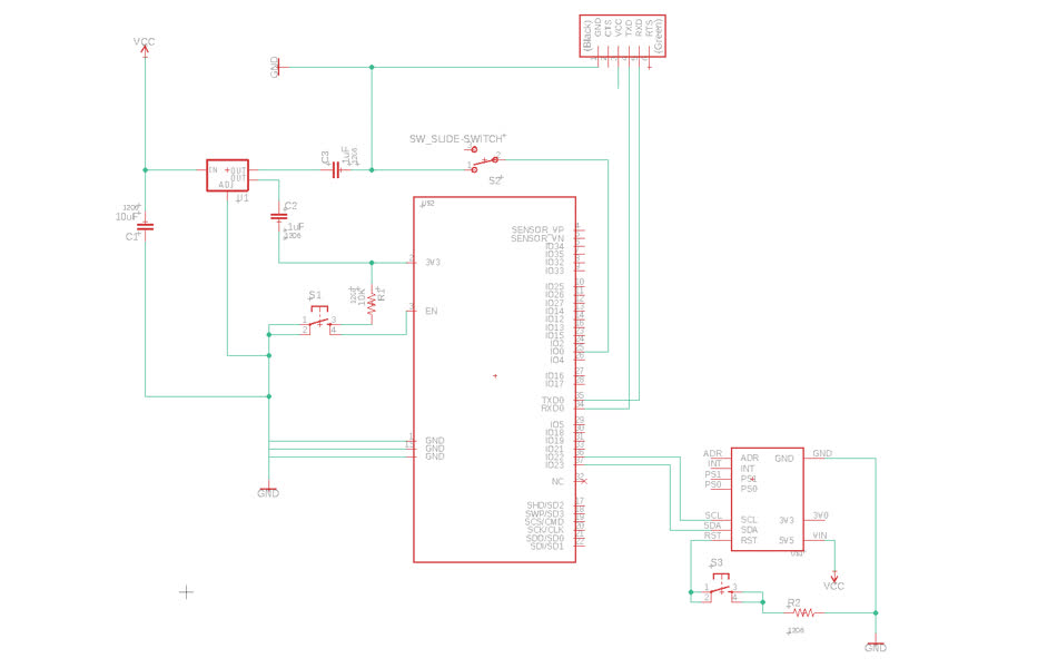
Neil has a weird slide switch on his board that's hooked up to an adjustable regulator(ZLDO1117) and the IO0 pin on the ESP32 .... why ???
referencing ESP32-WROOM datasheet - the IO0 pin on the ESP32 is a "strapping pin" - it has in internal pull-up resistor that changes the booting mode when the chip is reset. If GPIO0 is 1 then SPI boot and is 0 then download boot, the default internal value is pull-up (1). So it's a switch to change the bootloader mode.
create schematic
everything from Neil's board is set up.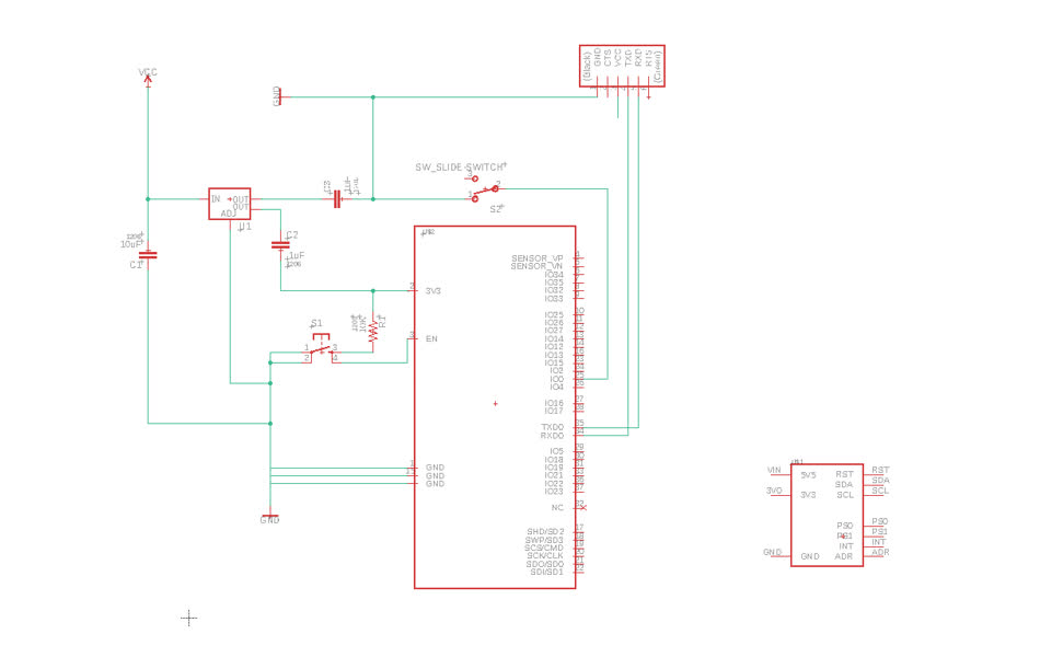
time to move over to feather to see if anything special is needed on the SPI pins.
already way too complicated
looking into doing it from scratch with this tutorial
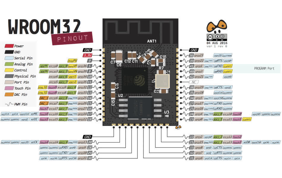
this is great. there's so much documentation on the esp32 - pinout guide
The tutorial says that the default arduino SDA and SCL pins are GPIO 21 and GPIO 22 respectively. But in the ESP32 feather (schematic), SCL is GPIO 22 and SDA is GPIO 23. I'm going to route mine following the feather's convention, since I've already had the libraries work with that configuration. If I run into problems though, I may need to explicitly set these values when programmming.
other than that, I added a reset button to be able to recalibrate the sensor.
Now time to figure out how to power this guy without the FTDI cable. Jake offered some recommendations : I could use the same power setup from the feather with the little LiPo batteries, or use a usb battery pack and add a usb connector to the board, or I could use a usb connector and directly solder usb wires to the board. listed in decreasing effort and elegance.
what would it take to mimic the feather's power supply system?
the lipo batteries are rechargable so the board would need to be able to be recharged with the ftdi connection and know to prioritize one over the other. there are two battery sections in the feather schematic
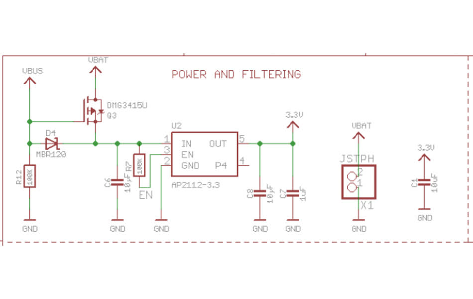
Pulling power and filtering it for ESP32.
parts needes:
- 3.3V 600 mA linear regulator - AP2112
- linear regulator with minimum 600mA output. fab inventory only has 100mA and 1A regulators. what requires 600mA?
- Schottky barrier rectifier - MBR120
- p-MOSFET - DMG3415U
- connector - JST PH 2pin
- LiPo battery - 3.7v 1200mAh
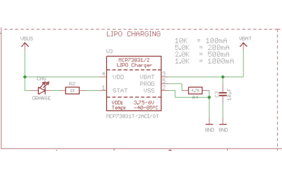
and charging the LiPo battery for power.
parts needed:
- some LEDs to show charging progress
- linear charge management controller - MCP73831T
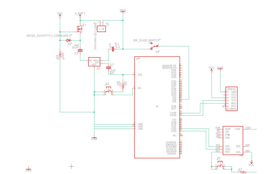
modifying for my stuff.
the feather board uses a 3.3V 600mA regulator on the power supply, but Neil's hellowork seems to be running fine with the 3.3V 1A regulator (ZLDO1117), which we have in stock so I'll use that one. (but need to double check that won't cause problems somewhere else).
then I just need the schottky diode to make sure v battery can't go straight into vcc, but it can still charge the battery. - could this just be a 1A schottky diode (641-1331-1-ND)?? zach said yah, thanks zach!
and the p-MOSFET - what is that doing? making sure current doesn't get weird between the battery voltage and charging voltage. this one behaves like a switch instead of just a blocker. can just use the fab inventory p-channel ones: NDS356APCT.
added the battery to the schematic. including all of the diodes to allow both the power from the ftdi and the batter at the same time.
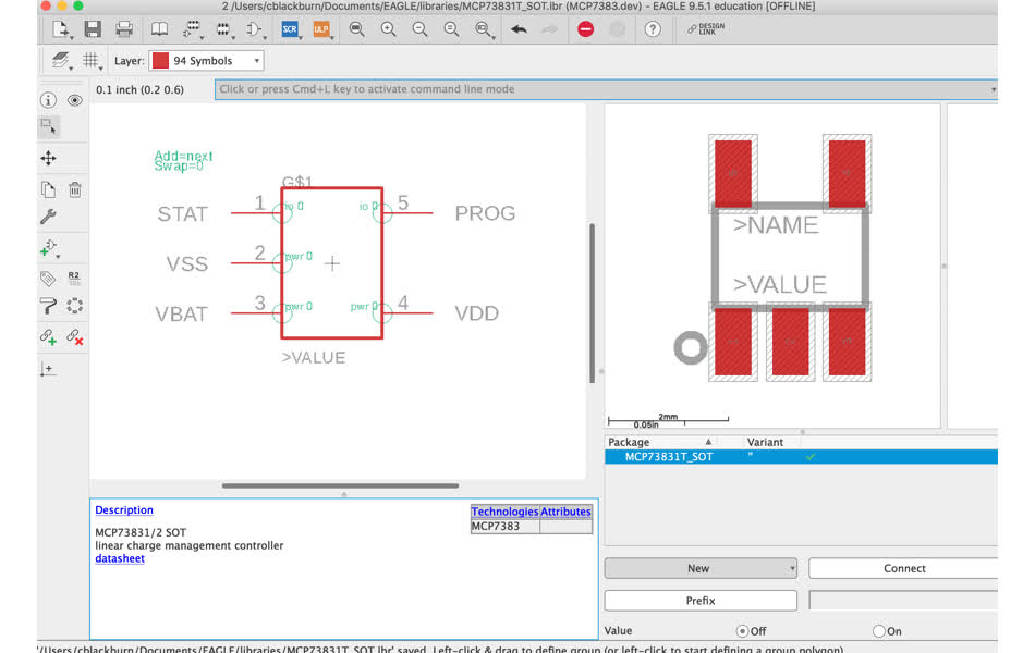
now adding the charging component . . . I need to make a custom footprint for the charge controller because it's not in the eagle fablab library.
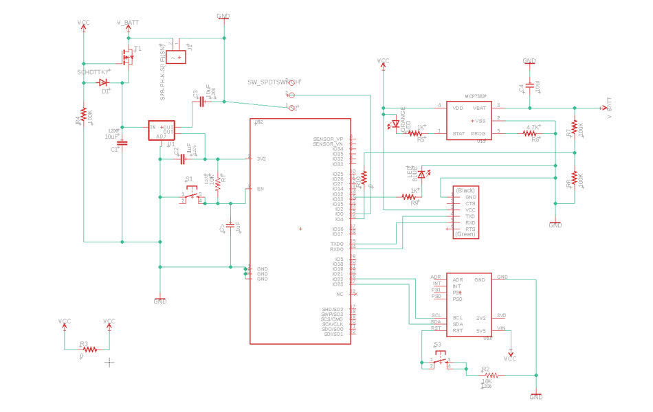
took much longer than I had expected, but finished the schematic
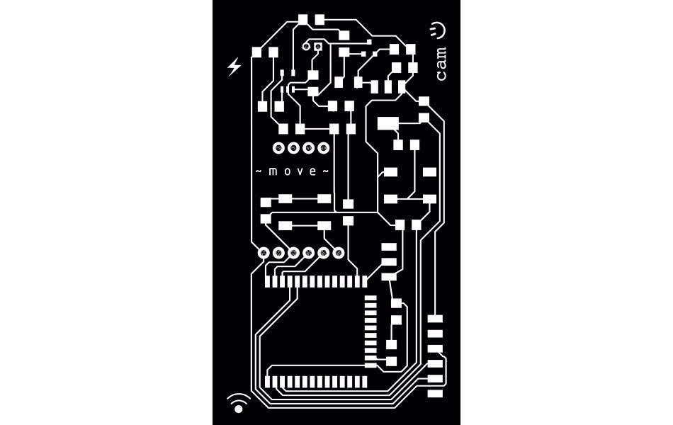
board layout
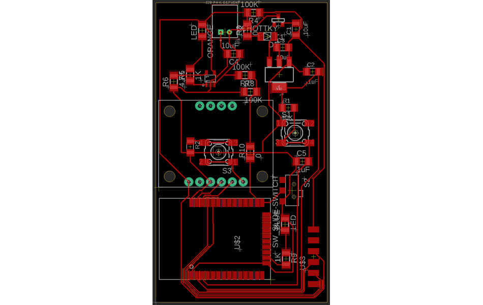
OK fun time - routing the board!moving battery charging pin out in ESP32 to 26 - IO4/GPIO4/ADC2_0, instead of 7 - IO35/GPIO35/ADC1_CH7 because it's easier to route and I think it should do the same thing.
complete board design
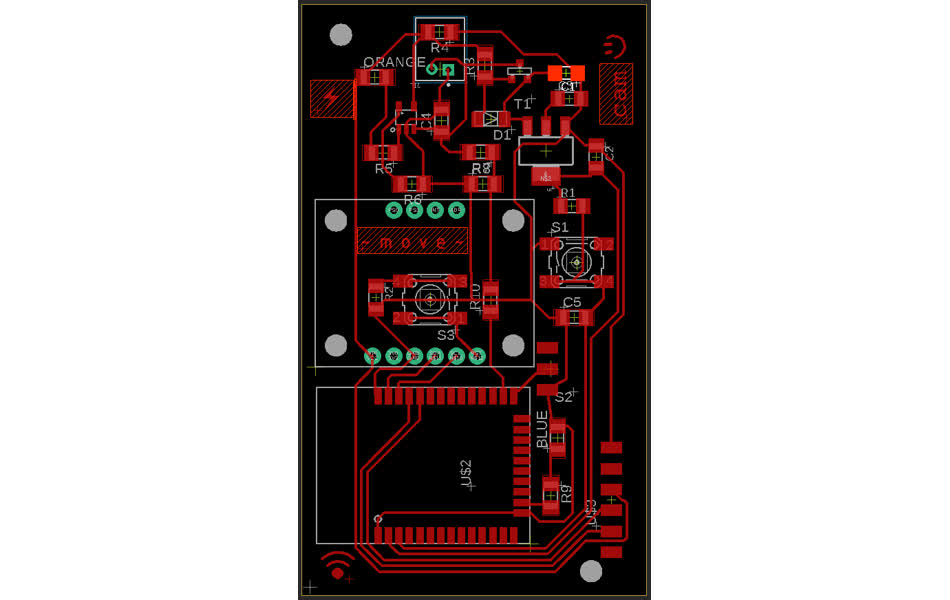
But I need to clean up a lot of the traces and footprints. The last few boards that I made had traces that didn't fully come out when I set the 16mil space design rule. I had assumed it was an Eagle problem, but Eric pointed it out that it was probably a mods issue instead. mods is really conservativewith trace width and I'm designing the baord right at the boundary limits, which could cause tiny merges in traces or landing pads that are too close, especially with the dpi conversion that typically isn't accurate down to the pixel. So, I bumped up the design rules to 12/18 trace/space and I'll triple check the calculated path in mods when sending it to the machine.
I also need to clean up the footprints for the ESP32 and MCP7383, and the vias holes on the JST connector because they are too big for the endmill. I edited the library footprint, but once you put a device in a project in Eagle, it no longer links it to the library file. So to update the changes on the board, right click the device in the schematic and "reload" the same one.
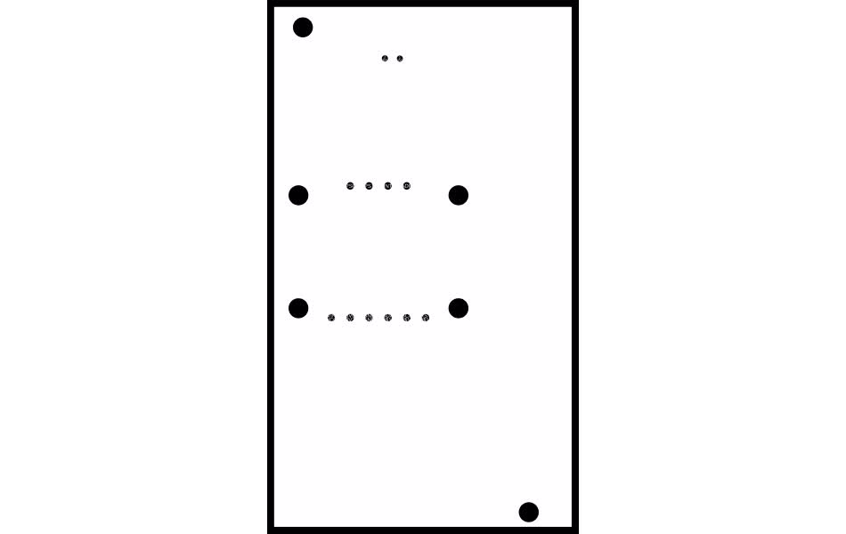
finally, this board has vias and drill mounting holes in it, which I've never worked with before. When exporting the board to an .png with the python script from here, the drill holes were not coming out as clear holes and the vias still contained all their text name. I tricked the script to recognizing the drill holes by adding a polygon around them in the 45 "Holes" layer. and drawing a circle polygon in eagle was NON-TRIVIAL ugh ~ you have to draw a diamond inscribed in whatever circle you want them manually adjust the curvature of each side to be 90. I couldn't figure out how to get rid of the text from the vias for the life of me ~ they're colored as if they are on the silk screen or an info layer, but then they remain when just looking at the via layer. I gave up because I figure mods won't pick up the tiny text anyway.
and the .png output
board assembly
milling
milling the board - load .png to mods. calculate dpi for proper measurement.42mm x 72mm (1.654 x 2.835 in) in eagle
4966 x 8505 in .png
dpi = 3002.4, 3000 zero:x100, y20
The top layer milled great, but then the cutout image was baaaad. First, mods couldn't pick up the via holes, probably becuase they don't look like holes since the text is floating through them. I doctored the image in GIMP. Then, the whole piece was cut before the vias and drill holes which cause the board to shake, get the endmill stuck inside of it, and break the endmill. I was worried about exactly that happenening before i sent the file, but the Eagle python script merges vias and holes with the cutout image so I assumed that this was standard and the tape could be enough to hold it. bad assumption. should've gone with my gut.
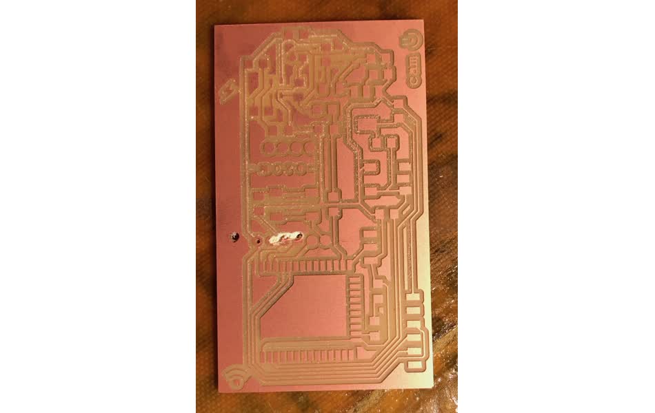
To solve it, I split the cutout into three different .pngs - one for holes, vias, and the cutout

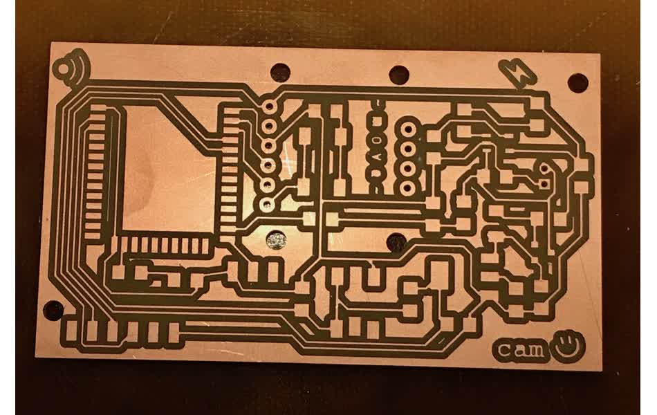
The board finally came out well
solder
Then time to solder . . .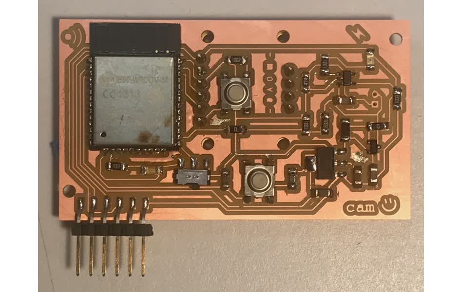
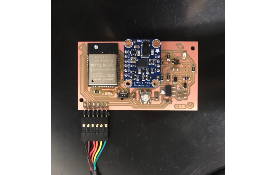
But when probing with a mulitmeter and trying to program the board, I realized that the BNO005 breakout is soldered backwards - it cannot be on the back because I didn't flip the footprint in the board layout. This is a bummer because I wanted the top to look clean, but it's not the end of the world becuase I can take it off and mount it to the top instead ~ it just blocks the reset button to zero the position of the orientation sensor, but maybe it's better to have that more inaccessible anyway.
then I tried hooking up the battery - this is the part I was most worried because cause I wasn't sure that I had the pins correct with the JST connector. I did : square via is ground, circle is Vbatt. but then I was dummmmbbb tested the connector along the top which swapped ground and voltage and cause the MCP7383 to blow up . . . it even burned off the copper traces on the board . . . :(
I don't have time to remake the board now, so I'll chug along with out battery power a bit and can potentially save the board with some frankenstein wiring once I need the battery.
some thoughts for a second iteration:
- no need for mounting holes for BNO055 - soldered connectors hold them together
- put filter capacitor closer to ESP32 input (this is general best practice with board design)
- make pads on ESP32 footprint longer for easier soldering and probing
- orient FTDI cable better so it fits on chip ~ or just remove it once better is used?
- add more debugging LEDs
programming
since i copied the ESP32 Feather pins, I'll program with that board. programming with platformio ESP32 Featherrunning
platformio init --board featheresp32 will initialze a featheresp32 project with default values found here, which can be overwritten if specified in the .ini file.
good platformio tutorial with ESP32 - I want to look into unit test with this, but it's not critical path a the moment; here
merging a couple tutorials found online (sensor example, wifi example, POST example), I got the ESP32 receiving data from the BNO055 sensor and sending it as a "dweet" that can be read online!!
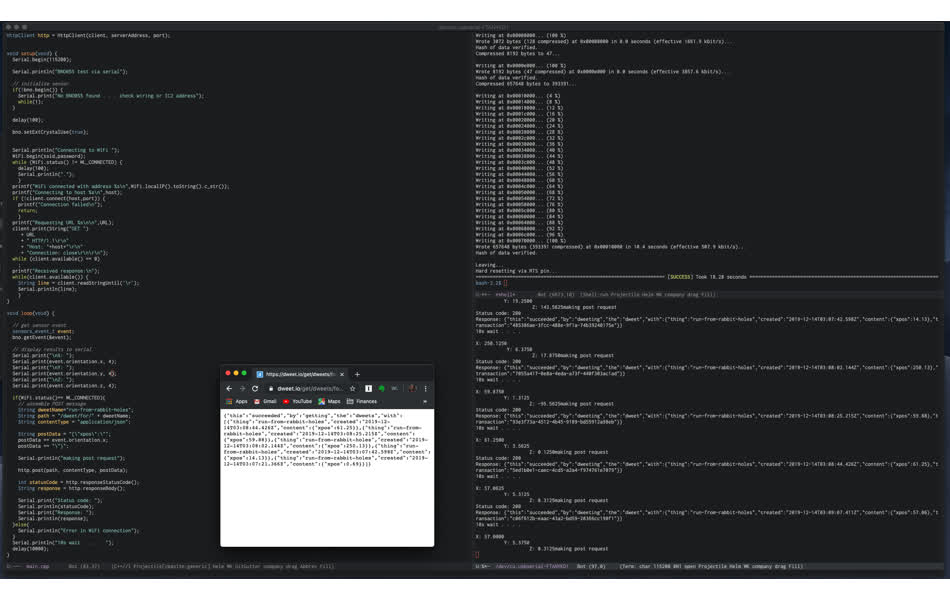
The left frame is the main.cpp compiled by platfomio and flashed to the ESP32 chip in the right top frame, then bottom right frame is the serial port ESP32 is writing to, and the chrome tab shows the POSTs from my chip on dweet. I've never appreciated softawre more - debugging was so beautifully seamless after the head banging morning that was soldering and beep tests!!!