PROCESS
To start, I began by characterizing the design rules, to see what are the thinnest traces a 1/64” endmill with a cut depth of .002 and a max cut depth of .004 can produce. Overall, the traces were in good shape, but it does get dicey around .02 mm. The results are shown below.

After that, I set about milling my own PCB. I found that a .004 max depth with a .002 cut depth resulted in nice traces. I then, carefully, switched the end mill to a 1/32” and cut out the PCB.
![]()
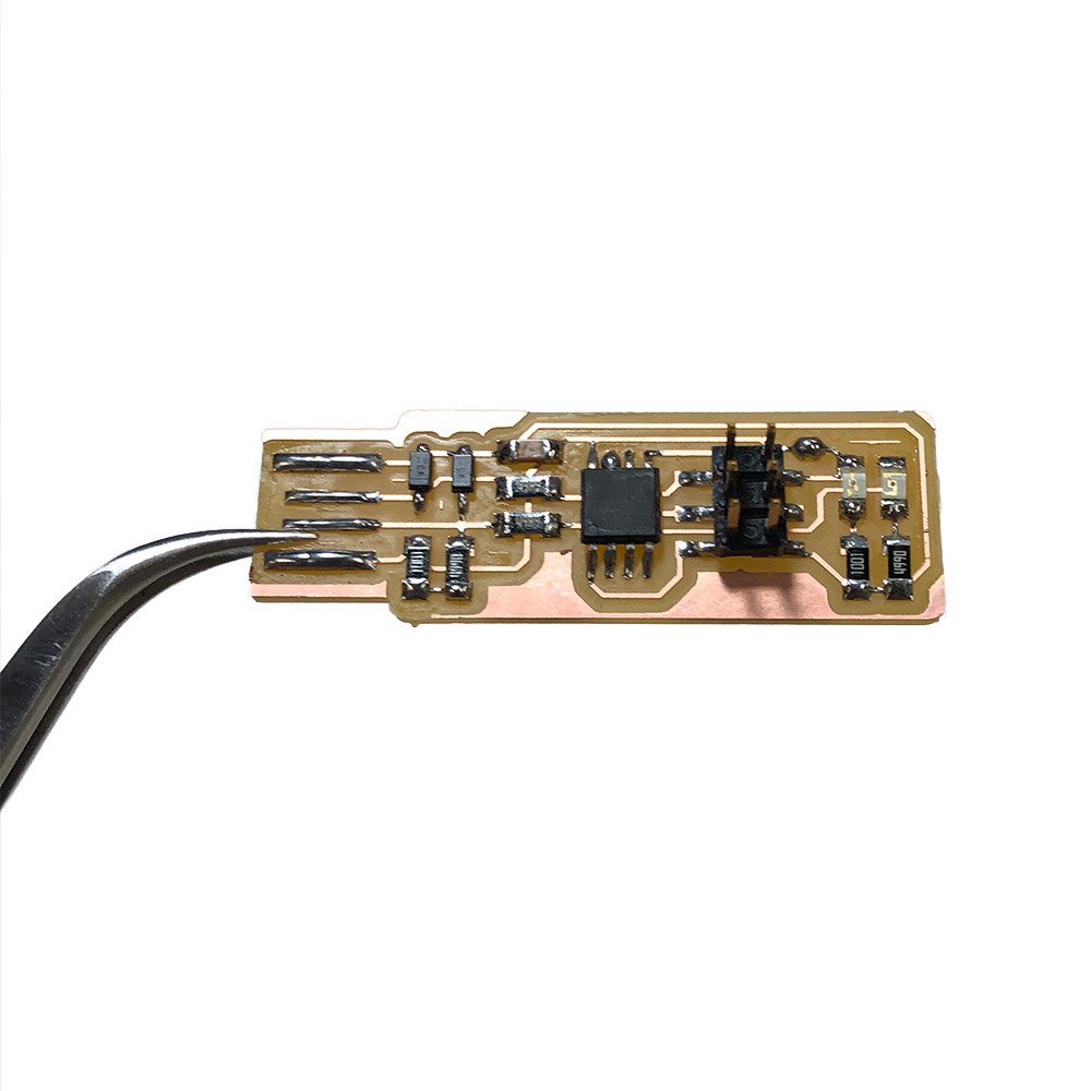
Once I had the blank PCB, I collected the components I needed and began soldering. Although I have a fair amount of experience soldering in undergrad and internships, I was nervous about this task because I have very shaky hands. I found using the microscope, and stabilizing my hand on the base of the microscope helped tremendously.

When soldering components onto the board, make sure the labeling matches the guide you are following. There were some resistors that were improperly sorted that almost caused me trouble. There were three things that I found important for good soldering: 1. Use a dab of solder to help secure a component in place 2. Give the component time to heat up before you introduce the solder 3. Extra flux is your friends
Now that everything was done, I had my board, which thankfully lit up and was able to be programmed on the first try.

