PROCESS
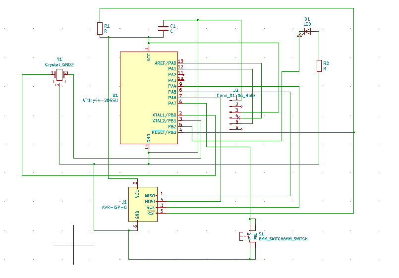
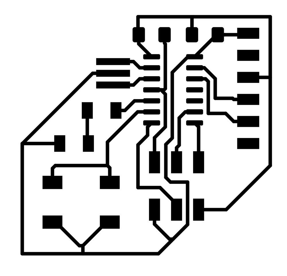
Using Kicad, and with some help from Zach Fredin, I was able to generate a replica of the "Echo Hello World Board". I added an additiona push button and LED (with current limiting resistor) on two unused pins.
I then generated the ratsnest of the board, and got to embark on the blissful process of detangling. I wanted to push my soldering skills, so I tried to make the board as compact as possible. In the design rules I set the traces with to be .4 mm.
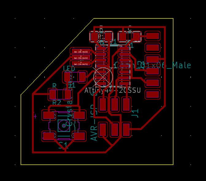
I then exported the board to a SVG file, and using Inkscape I converted it to a png.
My first attempt to mill failed in a few ways: 1) The DPI of the PNG that mods detected was different than the actual DPI, so the circuit ended up being about 33% larger 2) The DPI of the PNG was way to low, so I got crookes lines
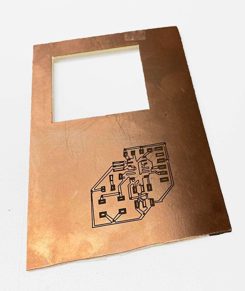
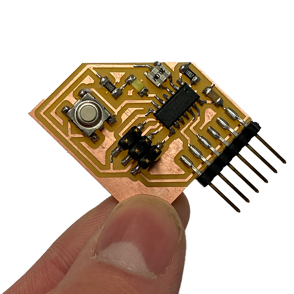
After uploading a higher resolution image and fixing the DPI, my second attempt was more succesful, and I was able to get it the components soldered.
I was NOT able to program the board on my computer, because USB-C is awful, so I used the Linux machine in the CBA lab.
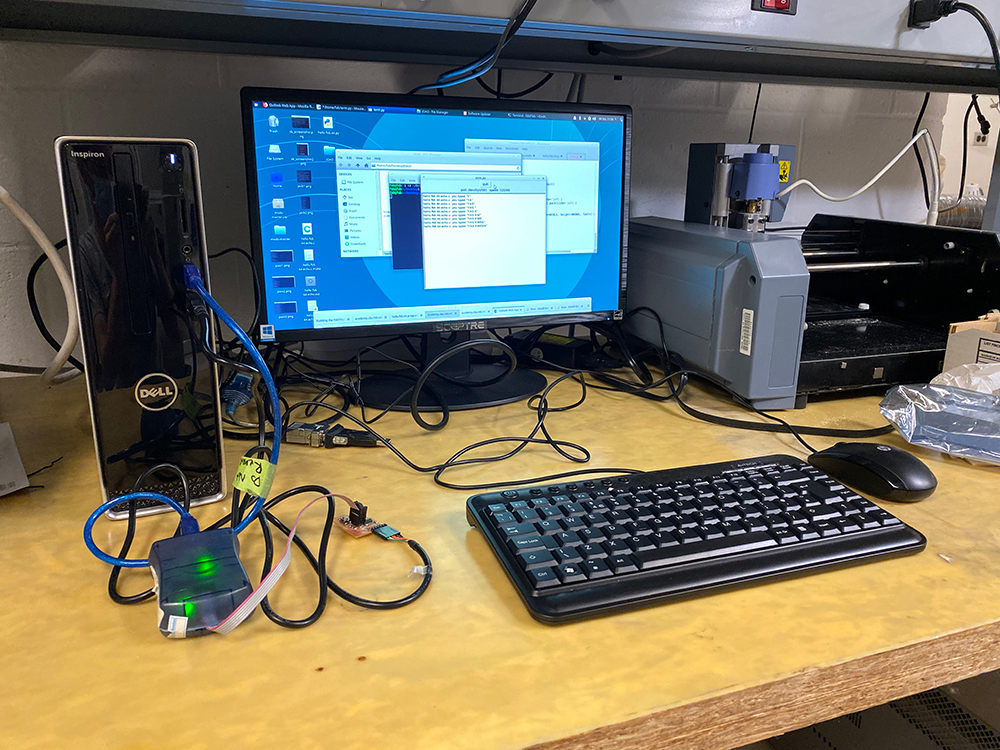
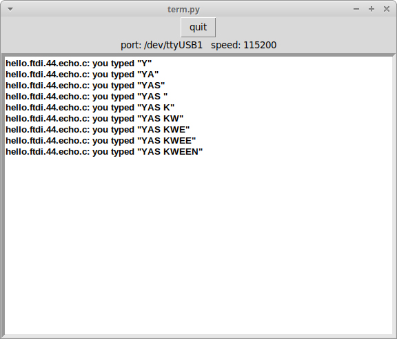
In the end, I was successfully able to program the board and run the term.py function on it!